Application Program Structure


During initialization, both the application program and its associated PSB are loaded from their respective libraries by the IMS system. The IMS modules interpret and execute database CALL requests issued by the program. These modules can reside in the same or different z/OS address spaces, depending on the environment in which the application program executes.

Application programs that execute in an online transaction environment are executed in a dependent region called the message processing region (MPR) or Fast Path region (IFP). The programs are often called message processing programs (MPPs). The IMS modules that execute online services run in the control region while the full-function database services run in the DL/I separate address space (DLISAS). The association of the application program and the PSB is defined at IMS system generation time through the APPLTN and TRANSACTION macros.

Batch application programs can execute in two different types of regions.

  • Application programs that need to make use of message processing services or databases being used by online systems execute in a batch message processing region (BMP).

  • Application programs that can execute without messages services execute in a DB batch region.

For both of these types of batch application programs, the association of the application program to the PSB is done on the PARM keyword on the EXEC statement.

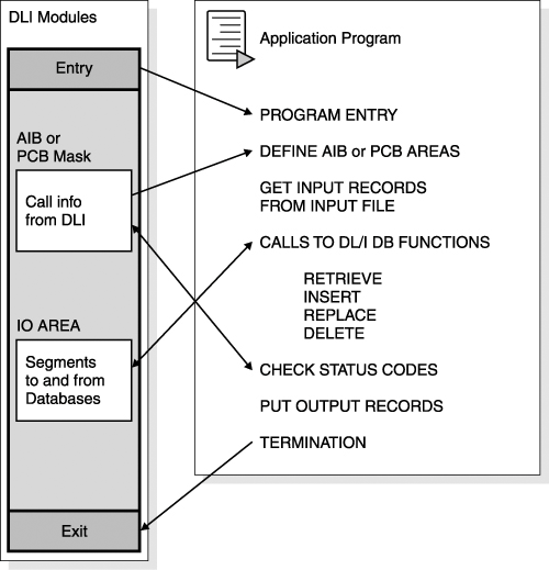
Figure 14-1 on page 219 illustrates how the program elements of an application program interface with IMS and are functionally structured. The program elements are:

Figure 14-1. Structure of an IMS Application Program


An ENTRY statement

The ENTRY statement specifies the PCBs utilized by the program (see "Entry to the Application Program" on page 220).

A PCB or AIB

IMS describes the results of each DL/I call using the AIBTDLI interface in the application interface block (AIB) and, when applicable, the program communication block (PCB). See "PCB Mask" on page 223. To find the results of the call using the AIBTDLI interface, your program must use the AIB. If your program references the PCB in the call, it must use that PCB to find the results of the DL/I call.

Your application program can use the PCB address that is returned in the AIB to find the results of the call. To use the PCB, the program defines a mask of the PCB and can then reference the PCB after each call to determine the success or failure of the call. An application program cannot change the fields in a PCB; it can only check the PCB to determine what happened when the call completed.

There are two types of PCBs: a database (DB) PCB and a telecommunication-program (TP) PCB.

An input/output (I/O) area

IMS passes segments to and from the program in the program's I/O area.

Some DL/I calls

The program issues DL/I calls to perform the requested function (see "Calls to IMS" on page 227).

A status code processing section

The program checks the status code for each DL/I call to find out if the call was successful (see "Status Code Processing" on page 228).

A termination statement

The program returns control to IMS when it has finished processing (see "Termination of the Application" on page 229). In a batch program, your program can set the return code and pass it to the next step in the job.

Recommendation:

If your program does not use the return code in this way, it is a good idea to set it to 0 as a programming convention. Your program can use the return code for this same purpose in BMP programs. MPPs cannot pass return codes.


The PCB mask and I/O area are described in the program's data declaration section. Program entry, calls to IMS processing, and program termination are described in the program's procedural section. Calls to IMS, processing statements, and program termination can reference PCB masks or I/O areas. In addition, IMS can reference these data areas.

The individual program elements mentioned in the previous list are discussed in the following sections.

Entry to the Application Program

As shown in Figure 14-1, IMS passes control to the application program through the entry point. At entry, all the PCBs or AIBs used by the application program are specified. The order of the PCB names in the ENTRY statement must be the same as in the PSB for this application program. The sequence of PCBs in the linkage section or declaration portion of the application program need not be the same as in the ENTRY statement.

IMS passes the PCB pointers to a PL/I program differently than it passes them to an assembler language, C language, COBOL, or Pascal program. In addition, Pascal requires that IMS pass an integer before passing the PCB pointers. IMS uses the LANG keyword or the PSBGEN statement of PSBGEN to determine the type of program to which it is passing control. Therefore, you must be sure that the language specified during PSBGEN is consistent with the language of the program.

Application interfaces that use the AIB structure (AIBTDLI or CEETDLI) use the PCB name rather than the PCB structure and do not require the PCB list to be passed at entry to the application program.

When you code each DL/I call, you must provide the PCB you want to use for that call. For all IMS TM application programs, the list of PCBs the program can access is passed to the program at its entry point.

Restriction:

DB batch programs cannot be passed parameter information using the PARM field from the EXEC statement.


AIB Mask

The AIB is used by your program to communicate with IMS when your application does not have a program communication block (PCB) address or the call function does not use a PCB. The AIB mask enables your program to interpret the control block defined. The AIB structure must be defined in working storage, on a fullword boundary, and initialized according to the order and byte length of the fields as shown in Table 14-1. The notes at the bottom of the table describe the contents of each field.

Table 14-1. AIB Fields

Descriptor

Byte Length

DB/DC

DBCTL

DCCTL

DB Batch

TM Batch

AIB identifier[1]

8

X

X

X

X

X

DFSAIB allocated length[2]

4

X

X

X

X

X

Subfunction code[3]

8

X

X

X

X

X

Resource name[4]

8

X

X

X

X

X

Reserved[5]

16


Maximum output area length[6]

4

X

X

X

X

X

Output area length used[7]

4

X

X

X

X

X

Reserved[8]

12


Return code[9]

4

X

X

X

X

X

Reason code[10]

4

X

X

X

X

X

Error code extension[11]

4

X


X


Resource address[12]

4

X

X

X

X

X

Reserved[13]

48


Notes:


[1] AIB Identifier (AIBID)
This 8-byte field contains the AIB identifier. You must initialize AIBID in your application program to the value DFSAIB. before you issue DL/I calls. This field is required. When the call is completed, the information returned in this field is unchanged.

[2] DFSAIB Allocated Length (AIBLEN)
This field contains the actual 4-byte length of the AIB as defined by your program. You must initialize AIBLEN in your application program before you issue DL/I calls. The minimum length required is 128 bytes. When the call is completed, the information returned in this field is unchanged. This field is required.

[3] Subfunction Code (AIBSFUNC)
This 8-byte field contains the subfunction code for those calls that use a subfunction. You must initialize AIBSFUNC in your application program before you issue DL/I calls. When the call is completed, the information returned in this field is unchanged.

[4] Resource Name (AIBRSNM1)
This 8-byte field contains the name of a resource. The resource varies depending on the call. You must initialize AIBRSNM1 in your application program before you issue DL/I calls. When the call is complete, the information returned in this field is unchanged. This field is required.
For PCB related calls where the AIB is used to pass the PCB name instead of passing the PCB address in the call list, this field contains the PCB name. The PCB name for the I/O PCB is IOPCB. The PCB name for other types of PCBs is defined in the PCBNAME= parameter in PSBGEN.

[5] Reserved
This 16-byte field is reserved.

[6] Maximum Output Area Length (AIBOALEN)
This 4-byte field contains the length of the output area in bytes that was specified in the call list. You must initialize AIBOALEN in your application program for all calls that return data to the output area. When the call is completed, the information returned in this area is unchanged.

[7] Used Output Area Length (AIBOAUSE)
This 4-byte field contains the length of the data returned by IMS for all calls that return data to the output area. When the call is completed this field contains the length of the I/O area used for this call.

[8] Reserved
This 12-byte field is reserved.

[9] Return code (AIBRETRN)
When the call is completed, this 4-byte field contains the return code.

[10] Reason Code (AIBREASN)
When the call is completed, this 4-byte field contains the reason code.

[11] Error Code Extension (AIBERRXT)
This 4-byte field contains additional error information depending on the return code in AIBRETRN and the reason code in AIBREASN.

[12] Resource Address (AIBRSA1)
When the call is completed, this 4-byte field contains call-specific information. For PCB related calls where the AIB is used to pass the PCB name instead of passing the PCB address in the call list, this field returns the PCB address.

[13] Reserved
This 48-byte field is reserved.

The application program can use the returned PCB address, when available, to inspect the status code in the PCB and to obtain any other information needed by the application program.

PCB Mask

A mask or skeleton PCB structure is used by the application program to access data from a TP PCB or DB PCB. One PCB is required for each view of a database or online service. The program views a hierarchical data structure by using the DB PCB mask. The program uses a TP PCB to communicate with a terminal or other application program. Figure 14-2 on page 224 shows the structure of a PCB mask and how that structure maps to the database.

Figure 14-2. Application PCB Structure
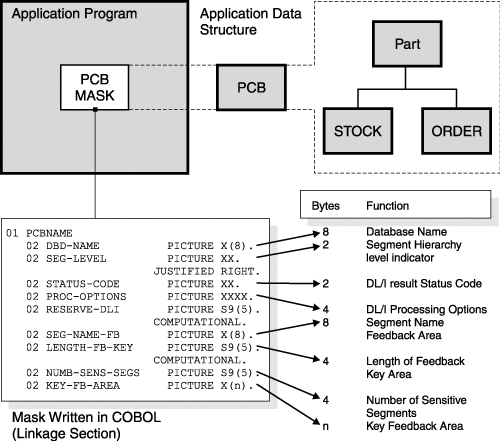

One PCB is required for each data structure. An example of a database PCB mask is shown in Figure 14-3 on page 225 and explained in the text that follows the figure. An example of a TP PCB mask is shown in Figure 14-5 on page 227.

Figure 14-3. Example of a DB PCB Mask in COBOL
 01 PCBNAME.    02 DBD-NAME          PICTURE X(8).    02 SEG-LEVEL         PICTURE XX.    02 STATUS-CODE       PICTURE XX.    02 PROC-OPTIONS      PICTURE XXXX.    02 RESERVED-DLI      PICTURE S9(5).    02 SEG-NAME          PICTURE X(8).    02 LENGTH-FB-KEY     PICTURE S9(5).    02 NUMB-SENS-SEGS    PICTURE S9(5).    02 KEY-FB-AREA       PICTURE X(n). 

Figure 14-5. Example of an Online Application PCB Mask
 01 IOPCB.       02 LTERM        PICTURE X(8).     Logical Terminal Name       02 FILLER       PICTURE XX.       Reserved       02 STATUS-CODE  PICTURE XX.       Status Code       02 LOCAL-TIME   PICTURE X(8).     Local Date/Time       02 SEQ-NUMBER   PICTURE X(4).     Input Message Sequence Number       02 MOD-NAME     PICTURE X(8).     Message output descriptor name       02 USERID       PICTURE X(8).     USERID       02 RACF         PICTURE X(8).     RACF Group       02 TIMESTMP     PICTURE X(12).    12-Byte Timestamp       02 USER-INDIC   PICTURE X.        Userid Indicator       02 FILLER       PICTURE X(3).     Reserved 

Define the PCB mask as an assembler DSECT, a COBOL linkage section entry, or a PL/I-based variable because the PCB does not actually reside in the application program.

The PCB provides specific areas used by IMS to inform the application program of the results of its calls. At execution time, all PCB entries are controlled by IMS. Access to the PCB entries by the application program is for read-only purposes. The PCB masks for a TP PCB and a database PCB are different.

DB PCB Mask

Figure 14-3 shows an example of a program's DB PCB mask, which defines the PCB area used by IMS to return the results of the call.

The following items comprise a PCB for a hierarchical data structure from a database:

Name of the PCB (PCBNAME)

The name of the area that refers to the entire structure of PCB fields. The PCB name is used in program statements. This name is not a field in the PCB. It is the 01 level name in the mask shown in Figure 14-3.

Name of the database (DBD-NAME)

The first field in the PCB, and provides the DBD name from the library of database descriptions associated with a particular database. It contains character data and is eight bytes long.

Segment hierarchy level indicator (SEG-LEVEL)

IMS uses this area to identify the level number of the last segment encountered that satisfied a level of the call. When a retrieve call is successful, the level number of the retrieved segment is placed here. If the retrieve is unsuccessful, the level number returned is that of the last segment that satisfied the search criteria along the path from the root (the root segment level being '01') to the desired segment. If the call is completely unsatisfied, the level returned is '00'. This field contains character data: it is two bytes long and is a right-justified, numeric value.

DL/I status code (STATUS-CODE)

A status code that indicates the results of the DL/I call is placed in this field and remains here until another DL/I call uses this PCB. This field contains two bytes of character data. When a successful call is executed, DL/I sets this field to blanks or to an informative status indicator. A complete list of DL/I status codes can be found in IMS Version 9: Messages and Codes, Volume 1.

DL/I processing options (PROC-OPTIONS)

This area contains a character code that tells DL/I the processing intent of the program against this database (that is, the kinds of calls that can be used by the program for processing data in this database). This field is four bytes long and is left-justified. It does not change from call to call. It gives the default value coded in the PCB PROCOPT parameter, although this value might be different for each segment. DL/I does not allow the application to change this field, nor any other field in the PCB.

Reserved area for IMS (RESERVED-DLI)

IMS uses this area for its own internal linkage related to an application program. This field is one fullword (four bytes), binary.

Segment name feedback area (SEG-NAME)

When a retrieve call is successful, IMS places the name of the retrieved segment here. If a retrieve is unsuccessful, the name returned is that of the last segment, along the path to the desired segment, that satisfied the search criteria. This field contains eight bytes of character data. This field may be useful in GN calls. If the status code is 'AI' (data management open error), the ddname of the related data set is returned in this area.

Length of key feedback area (LENGTH-FB-KEY)

This area specifies the current active length of the key feedback area. This field is one fullword (four bytes), binary.

Number of sensitive segments (NUMB-SENS-SEGS)

This area specifies the number of segment types in the database to which the application program is sensitive. This would represent a count of the number of segments in the logical data structure viewed through this PCB. This field is one fullword (four bytes), binary.

Key feedback area (KEY-FB-AREA)

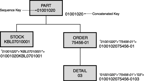
IMS places in this area the concatenated key of the last segment encountered that satisfied a level of the call. When a retrieve call is successful, the key of the requested segment and the key field of each segment along the path to the requested segment are concatenated and placed in this area. The key fields are positioned from left to right, beginning with the root segment key and following the hierarchical path. Figure 14-4 on page 227 shows examples of concatenated keys.

Figure 14-4. Examples of Concatenated Keys


When a retrieve call is unsuccessful, the keys of all segments along the path to the requested segment for which the search was successful are placed in this area. Segments without sequence fields are not represented in this area.

Recommendation:

Do not use the key feedback area after a completed unsuccessful call because this area is never cleared and it will contain information from a previous call.


TP PCB Mask

Figure 14-5 shows an example of an online program's PCB mask, which defines the PCB area used by IMS to return the results of the call.

Calls to IMS

Actual processing of IMS messages, commands, databases, and services is accomplished using a set of input and output functional call requests. A call request is composed of a CALL statement with a parameter list. The parameter list varies, depending on the type of call to be made. The call request consists of the following components:

  • A function call

  • An AIB identifier or PCB name

  • I/O area

  • Segment search argument (SSA) (database calls only)

Table 14-2 briefly describes the components of a call request. The call request components for database processing are discussed in more detail in Chapter 15, "Application Programming for the IMS Database Manager," on page 241. The online services and commands call request components are discussed in more detail in Chapter 16, "Application Programming for the IMS Transaction Manager," on page 281.

Table 14-2. IMS Call Request Components

Call Request Component

Description

Function call

Identifies the DL/I function[a] to be performed. This argument is the name of the 4-character field that describes the I/O operation.

AIB name or PCB name

The AIB name specifies the name of the pointer variable that contains the address of the structure that defines the application interface block (AIB) in user-defined storage. For more information on the contents of the AIB, see "AIB Mask" on page 221. The PCB name is the name of the PCB within the PSB that identifies which specific data structure the application program wants to process. The PCB is defined in more detail in "PCB Mask" on page 223.

I/O area

The name of an I/O work area of the application program into which DL/I puts a requested segment, or from which DL/I takes a designed segment. If this is a common area used to process multiple calls, it must be long enough to hold the longest path of segments to be processed.

SSA1...SSAn

The names of the Segment Search Arguments (SSAs), which are optional, depending on the type of call issued. Used only for database calls. The SSA provides information to define the segment to be retrieved or written.


[a] The DL/I functions are completely described in IMS Version 9: Application Programming: Database Manager and IMS Version 9: Application Programming: Transaction Manager.

Status Code Processing

After each IMS call, a 2-byte status code is returned in the AIB or PCB that is used for that call. There are three categories of status codes:

  • The blank status code, which indicates a successful call

  • Exceptional conditions and warning status codes, from an application point of view

  • Error status codes, specifying an error condition in the application program or IMS

The grouping of status codes in these categories somewhat depends on the installation. It is recommended that you use a standard procedure for status code checking and the handling of error status codes. The first two categories should be handled by the application program after each single call. Figure 14-6 shows an example of a COBOL application program that is testing status codes.

Figure 14-6. Example of a COBOL Application Program Testing Status Codes
 CALL 'CBLTDLI' USING.... IF PCB-STATUS EQ 'GE' PERFORM PRINT-NOT-FOUND. IF PCB STATUS NE '' PERFORM STATUS-ERROR. everything okay, proceed... 

Notice that it is more convenient to directly test the regular exceptions inline instead of branching to a status code check routine. In this way, you clearly see the processing of conditions that you want to handle from an application point of view, leaving the real error situations to a central status code error routine.

Termination of the Application

At the end of the processing of the application program, control must be returned to the IMS control program. Table 14-3 shows examples of the termination statements.

Table 14-3. Examples of Termination Statements in Different Languages

Language

Termination Statement

Assembler

RETURN(14,12),RC=0

COBOL

GOBACK.

Java

return;

PL/I

RETURN;


For application programs that are written in C or C++, when there are no more messages for the program to process, the program returns control to IMS by returning from main or by calling exit(). For application programs that are written in Pascal, when there are no more messages for your MPP to process, you return control to IMS by exiting the PASCIMS procedure. You can also code a RETURN statement to leave at another point.

Warning:

Returning to IMS causes storage that was occupied by your program to be released because IMS links to your application program. Therefore, you should close all non-DL/I data sets for COBOL and Assembler before return, to prevent abnormal termination during close processing by z/OS. PL/I automatically causes all files to be closed upon return.


Introduction to IMS. Your Complete Guide to IBM's Information Management System
An Introduction to IMS: Your Complete Guide to IBMs Information Management System
ISBN: 0131856715
EAN: 2147483647
Year: 2003
Pages: 226

flylib.com © 2008-2017.
If you may any questions please contact us: flylib@qtcs.net