The Minimal Spanning Tree Problem
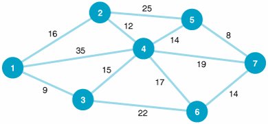
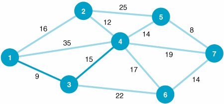
| In the shortest route problem presented in the previous section, the objective was to determine the shortest routes between the origin and the destination nodes in the network. In our example, we determined the best route from Los Angeles to each of the six destination cities. The minimal spanning tree problem is similar to the shortest route problem, except that the objective is to connect all the nodes in the network so that the total branch lengths are minimized. The resulting network spans (connects) all the points in the network at a minimum total distance (or length). The minimal spanning tree problem is to connect all nodes in a network so that the total branch lengths are minimized . To demonstrate the minimal spanning tree problem, we will consider the following example. The Metro Cable Television Company is to install a television cable system in a community consisting of seven suburbs. Each of the suburbs must be connected to the main cable system. The cable television company wants to lay out the main cable network in a way that will minimize the total length of cable that must be installed. The possible paths available to the cable television company (by consent of the town council) and the feet of cable (in thousands of feet) required for each path are shown in Figure 7.11. Figure 7.11. Network of possible cable TV paths
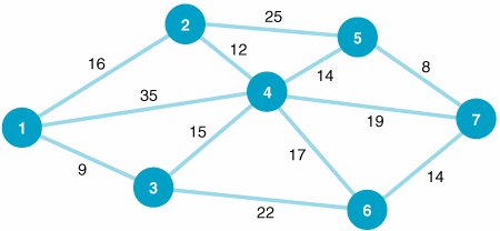
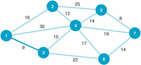
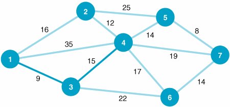
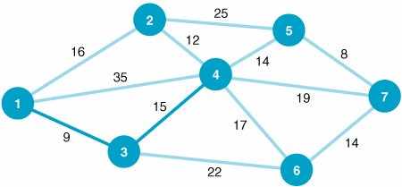
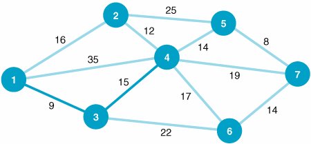
In Figure 7.11 the branch from node 1 to node 2 represents the available cable path between suburbs 1 and 2. The branch requires 16,000 feet of cable. Notice that the network shown in Figure 7.11 is identical to the network in Figure 7.2 that we used to demonstrate the shortest route problem. The networks were intentionally made identical to demonstrate the difference between the results of the two types of network models. The Minimal Spanning Tree Solution ApproachThe solution approach to the minimal spanning tree problem is actually easier than the shortest route solution method. In the minimal spanning tree solution approach, we can start at any node in the network. However, the conventional approach is to start with node 1. Beginning at node 1, we select the closest node (i.e., the shortest branch) to join our spanning tree. The shortest branch from node 1 is to node 3, with a length of 9 (thousand feet). This branch is indicated with a heavy line in Figure 7.12. Now we have a spanning tree consisting of two nodes: 1 and 3. The next step is to select the closest node not now in the spanning tree. The node closest to either node 1 or node 3 (the nodes in our present spanning tree) is node 4, with a branch length of 15,000 feet. The addition of node 4 to our spanning tree is shown in Figure 7.13. Figure 7.12. Spanning tree with nodes 1 and 3 Figure 7.13. Spanning tree with nodes 1, 3, and 4 Start with any node in the network and select the closest node to join the spanning tree. Select the closest node to any node in the spanning area . Next, we repeat the process of selecting the closest node to our present spanning tree (nodes 1, 3, and 4). The closest node not now connected to the nodes in our spanning tree is node 2. The length of the branch from node 4 to node 2 is 12,000 feet. The addition of node 2 to the spanning tree is shown in Figure 7.14. Figure 7.14. Spanning tree with nodes 1, 2, 3, and 4 Our spanning tree now consists of nodes 1, 2, 3, and 4. The node closest to this spanning tree is node 5, with a branch length of 14,000 feet to node 4. Thus, node 5 joins our spanning tree, as shown in Figure 7.15. Figure 7.15. Spanning tree with nodes 1, 2, 3, 4, and 5 The spanning tree now contains nodes 1, 2, 3, 4, and 5. The closest node not currently connected to the spanning tree is node 7. The branch connecting node 7 to node 5 has a length of 8,000 feet. Figure 7.16 shows the addition of node 7 to the spanning tree. Figure 7.16. Spanning tree with nodes 1, 2, 3, 4, 5, and 7 Now our spanning tree includes nodes 1, 2, 3, 4, 5, and 7. The only remaining node not connected to the spanning tree is node 6. The node in the spanning tree closest to node 6 is node 7, with a branch length of 14,000 feet. The complete spanning tree, which now includes all seven nodes, is shown in Figure 7.17. Figure 7.17. Minimal spanning tree for cable TV network(This item is displayed on page 285 in the print version) The spanning tree shown in Figure 7.17 requires the minimum amount of television cable to connect the seven suburbs72,000 feet. This same minimal spanning tree could have been obtained by starting at any of the six nodes other than node 1. Notice the difference between the minimal spanning tree network shown in Figure 7.17 and the shortest route network shown in Figure 7.10. The shortest route network represents the shortest paths between the origin and each of the destination nodes (i.e., six different routes). In contrast, the minimal spanning tree network shows how to connect all seven nodes so that the total distance (length) is minimized. In summary, the steps of the minimal spanning tree solution method are as follows :
Steps of the minimal spanning tree solution method . Computer Solution of the Minimal Spanning Tree Problem with QM for WindowsThe minimal spanning tree solution for our Metro Cable Television Company example using QM for Windows is shown in Exhibit 7.6. Exhibit 7.6.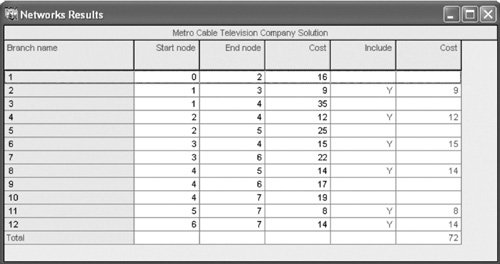 |
EAN: 2147483647
Pages: 358
