This chapter is from the Microsoft Windows Security Resource Kit by Ben Smith and Brian Komar with the Microsoft Security Team (Microsoft Press, 2003).
TCP/IP is an industry-standard suite of protocols designed to facilitate communication between computers on large networks. TCP/IP was developed in 1969 by the U.S. Department of Defense Advanced Research Projects Agency (DARPA), as the result of a resource-sharing experiment called ARPANET (Advanced Research Projects Agency Network). Since 1969, ARPANET has grown into a worldwide community of networks known as the Internet, and TCP/IP has become the primary protocol used on all networks. Unfortunately, TCP/IP was not designed with security in mind and thus has very few security components by default. Consequently, it is often a source of network vulnerabilities. On your Microsoft Windows 2000 and Windows XP computers, you can secure the TCP/IP protocol in several ways, which include securing the TCP/IP stack itself and using IP Security (IPSec). We will examine both techniques in this chapter.
Securing TCP/IP
You cannot successfully secure computer networks without knowing how TCP/IP works. Nearly all computers today use TCP/IP as their primary network communication protocol. Thus, without physical access to a computer, an attacker must use TCP/IP to attack it. Consequently, TCP/IP security is often your first line of defense against attackers attempting to compromise your organization s network and therefore should be part of any defense-in-depth strategy for securing networks. You can secure the TCP/IP protocol in Windows 2000 and Windows XP to protect a computer against common attacks, such as denial-of-service attacks, and to help prevent attacks on applications that use the TCP/IP protocol.
Understanding Internet Layer Protocols
TCP/IP primarily operates at two levels in the OSI model: the Internet layer and the transport layer. The Internet layer is responsible for addressing, packaging, and routing functions. The core protocols of the Internet layer include the Internet Protocol (IP), Address Resolution Protocol (ARP), and Internet Control Message Protocol (ICMP):
IP A routable protocol responsible for logical addressing, routing, and the fragmentation and reassembly of packets
ARP Resolves IP addresses to Media Access Control (MAC) addresses and vice versa
ICMP Provides diagnostic functions and reporting errors for unsuccessful delivery of IP packets
The TCP/IP protocol suite includes a series of interconnected protocols called the core protocols. All other applications and protocols in the TCP/IP protocol suite rely on the basic services provided by several protocols, including IP, ARP, and ICMP.
IP
IP is a connectionless, unreliable datagram protocol primarily responsible for addressing and routing packets between hosts. Connectionless means that a session is not established to manage the exchange data. Unreliable means that delivery is not guaranteed. IP always makes a best-effort attempt to deliver a packet. An IP packet might be lost, delivered out of sequence, duplicated, or delayed. IP does not attempt to recover from these types of errors. The acknowledgment of packets delivered and the recovery of lost packets is the responsibility of a higher-layer protocol, such as TCP. IP is defined in RFC 791.
An IP packet consists of an IP header and an IP payload. The IP header contains information about the IP packet itself, and the IP payload is the data being encapsulated by the IP protocol to be transmitted to the receiving host. The following list describes the key fields in the IP header:
Source IP Address The IP address of the source of the IP datagram.
Destination IP Address The IP address of the destination of the IP datagram.
Identification Used to identify a specific IP datagram and all fragments of a specific IP datagram if fragmentation occurs.
Protocol Informs IP at the destination host whether to pass the packet up to TCP, UDP, ICMP, or other protocols.
Checksum A simple mathematical computation used to verify the integrity of the IP header. If the IP header does not match the checksum, the receiving host will disregard the packet. This checksum does not include any information outside the IP header.
Time To Live (TTL) Designates the number of networks on which the datagram is allowed to travel before being discarded by a router. The TTL is set by the sending host and used to prevent packets from endlessly circulating on an IP network. When forwarding an IP packet, routers decrease the TTL by at least one.
Fragmentation And Reassembly If a router receives an IP packet that is too large for the network to which the packet is being forwarded, IP fragments the original packet into smaller packets that fit on the downstream network. When the packets arrive at their final destination, IP on the destination host reassembles the fragments into the original payload. This process is referred to as fragmentation and reassembly. Fragmentation can occur in environments that have a mix of networking technologies, such as Ethernet and Token Ring. The fragmentation and reassembly works as follows:
When an IP packet is sent, the sending host places a unique value in the Identification field.
The IP packet is received at the router. If the router determines that the Maximum Transmission Unit (MTU) of the network onto which the packet is to be forwarded is smaller than the size of the IP packet, the router fragments the original IP payload into multiple packets, each of which is smaller than the receiving network s MTU size. Each fragment is sent with its own IP header that contains the following:
The original Identification field, which identifies all fragments that belong together.
The More Fragments flag, which indicates that other fragments follow. The More Fragments flag is not set on the last fragment because no other fragments follow it.
The Fragment Offset field, which indicates the position of the fragment relative to the original IP payload.
When the fragments are received by the destination host, they are identified by the Identification field as belonging together. The Fragment Offset field is then used to reassemble the fragments into the original IP payload.
ARP
Address Resolution Protocol performs IP address to MAC address resolution for outgoing packets. As each outgoing addressed IP datagram is encapsulated in a frame, source and destination MAC addresses must be added. Determining the destination MAC address for each frame is the responsibility of ARP. ARP is defined in RFC 826.
ICMP
Internet Control Message Protocol provides troubleshooting facilities and error reporting for packets that are undeliverable. For example, if IP is unable to deliver a packet to the destination host, ICMP sends a Destination Unreachable message to the source host. Table 18-1 shows the most common ICMP messages.
Table 18-1: Common ICMP Messages
Message
Description
Echo Request
Troubleshooting message used to check IP connectivity to a desired host. The Ping utility sends ICMP Echo Request messages.
Echo Reply
Response to an ICMP Echo Request.
Redirect
Sent by a router to inform a sending host of a better route to a destination IP address.
Source Quench
Sent by a router to inform a sending host that its IP datagrams are being dropped because of congestion at the router. The sending host then lowers its transmission rate.
Destination Unreachable
Sent by a router or the destination host to inform the sending host that the datagram cannot be delivered.
When the result of an ICMP request is a Destination Unreachable message, a specific message is returned to the requestor detailing why the Destination Unreachable ICMP message was sent. Table 18-2 describes the most common of these messages.
Table 18-2: Common ICMP Destination Unreachable Messages
Unreachable Message
Description
Host Unreachable
Sent by an IP router when a route to the destination IP address cannot be found
Protocol Unreachable
Sent by the destination IP node when the Protocol field in the IP header cannot be matched with an IP client protocol currently loaded
Port Unreachable
Sent by the destination IP node when the destination port in the UDP header cannot be matched with a process using that port
Fragmentation Needed and DF Set
Sent by an IP router when fragmentation must occur but is not allowed because of the source node setting the Don t Fragment (DF) flag in the IP header
ICMP does not make IP a reliable protocol. ICMP attempts to report errors and provide feedback on specific conditions. ICMP messages are carried as unacknowledged IP datagrams and are themselves unreliable. ICMP is defined in RFC 792.
Understanding Transport Layer Protocols
The transport layer is responsible for providing session and datagram communication services over the IP protocol. The two core protocols of the transport layer are the Transmission Control Protocol (TCP) and User Datagram Protocol (UDP):
TCP Provides a one-to-one, connection-oriented, reliable communications service. TCP is responsible for the establishment of a TCP connection, the sequencing and acknowledgment of packets sent, and the recovery of packets lost during transmission.
UDP Provides a one-to-one or one-to-many, connectionless, unreliable communications service. UDP is used when the amount of data to be transferred is small (such as data that fits into a single packet), when the overhead of establishing a TCP connection is not desired, or when the applications or upper layer protocols provide reliable delivery.
How TCP Communication Works
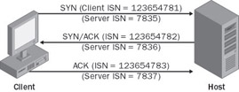
When two computers communicate using TCP, the computer that initiates the communication is known as the client, regardless of whether it is running a client or server OS, and the responding computer is known as the host. If the client and host are on the same network segment, the client computer first uses ARP to resolve the host s MAC address by sending a broadcast for the IP address of the host. Once the client has the MAC address of the host, it can commence communication to the port on the host by using the transport layer protocol specified by the application. There are 65,535 TCP and UDP ports, beginning with 0. Ports 1023 and below are regarded as well-known ports for legacy reasons, and ports above 1023 are known as high ports. Functionally, no difference exists between the well-known ports and the high ports. On the host, an application is bound to a certain port it specifies and is initialized in a listening state, where it waits for requests from a client. When the client initiates a connection to a TCP port, a defined series of packets, known as a three-way handshake and illustrated in Figure 18-1, constructs a session for reliable packet transmission. The steps for establishing connections follow:
The client sends the host a synchronization (SYN) message that contains the host s port and the client s Initial Sequence Number (ISN). TCP sequence numbers are 32 bits in length and used to ensure session reliability by facilitating out-of-order packet reconstruction.
The host receives the message and sends back its own SYN message and an acknowledgement (ACK) message, which includes the host s ISN and the client s ISN incremented by 1.
The client receives the host s response and sends an ACK, which includes the ISN from the host incremented by 1. After the host receives the packet, the TCP session is established.
Figure 18-1: Three-way TCP handshake
When the communication between the client and host is complete, the session is closed once the following steps occur:
The client sends a finalization (FIN) message to the host. The session is now half closed. The client no longer sends data but can still receive data from the host. Upon receiving this FIN message, the host enters a passive closed state.
The host sends an ACK message, which includes the client s sequence number augmented by 1.
The server sends its own FIN message. The client receives the FIN message and returns an ACK message that includes the host s sequence number augmented by 1.
Upon receiving this ACK message, the host closes the connection and releases the memory the connection was using.
The Netstat.exe Command
To see port activity on your Windows 2000 or Windows XP computers, you can use the Netstat.exe command. Netstat.exe will also show the status of TCP ports. The syntax for using Netstat.exe follows, and Table 18-3 describes the options available when using this command.
Displays Ethernet statistics. This can be combined with the -s option.
-n
Displays addresses and port numbers in numerical form.
-o
Displays the owning process ID (PID) associated with each connection. This option exists in Windows XP only.
-p protocol
Shows connections for the protocol specified by protocol, which can be TCP, UDP, TCPv6, or UDPv6. If used with the -s option to display per-protocol statistics, the value for protocol can be IP, ICMP, TCP, or UDP.
-r
Displays the routing table.
-s
Displays per-protocol statistics. By default, statistics are shown for IP, ICMP, TCP, and UDP.
interval
Determines the refresh interval for the data displayed by Net stat.
Tip
To find the process associated with a given active port in Windows XP, you can locate the PID associated with the port by typing netstat aon. You can then find the process associated with the PID by typing tasklist FI PID eq XX,where XX is the PID of the process.
As mentioned in Table 18-3, the -o option of Netstat.exe is not available in Windows 2000; however, you can download utilities from the Internet that have similar functionality and will run on Windows 2000.
Common Threats to TCP/IP
Several types of threats to TCP/IP can either compromise network security or lead to information disclosure. Although these attacks are more prevalent on the Internet, you should be concerned about them on internal computers as well. These common threats include:
Port scanning
Spoofing
Denial of service
Port Scanning
In order to communicate with TCP/IP, applications running on host computers must listen for incoming TCP or UDP connections, and host operating systems must listen for broadcast and other network maintenance traffic. By scanning a computer to see what ports a host is listening for and what protocols it uses, an attacker might be able to locate weaknesses in the host that he can later use to attack the computer. Attackers often perform port scans to reveal this information. Several types of port scans exist:
Ping sweeps An attacker might use an automated tool to send ICMP Echo Request packets to entire networks or subnets. By default, all active hosts will respond. This lets the attacker know that the host exists and is active. An attacker can also analyze the structure of the ICMP packet to determine the OS running on the host.
Port enumeration At attacker might want to enumerate all the services running on a host computer. Because hosts must respond to client computers to carry out legitimate operations, attackers can exploit this behavior to obtain critical information.
Tip
You can download a command-line port-scanning tool from Microsoft called Portqry.exe. This tool, found at http://www.microsoft.com/downloads/release.asp?ReleaseID=37344 tests the security of hosts and performs network diagnostics. In addition, many free utilities that can perform port scans are available on the Internet.
Banner grabbing Many common services respond with banners when sessions are initiated or requested. These banners contain basic information on the service or server. For example, by using Telnet to connect to port 25 of a Windows 2000 server running the default Simple Mail Transfer Protocol (SMTP) service, you can retrieve this banner:
220 SFOFS001.finance.woodgrovebank.com Microsoft ESMTP MAIL Service,
  Version: 5.0 .2195.5329 ready at Sat, 12 Oct 2002 16:18:44 -0800
From interpreting this banner, you can determine that the target server is named SFOFS001. SFOFS001 is probably a file server running Windows 2000 with Service Pack 3 installed and is physically located in the Pacific Time zone most likely in San Francisco. The server is running a built-in instance of the SMTP service, which is installed as part of Microsoft Internet Information Services (IIS) 5.0. Knowing that IIS is installed by default in Windows 2000 and that this server does not appear to be a Web server, it is likely that the server has a default installation of Windows 2000.
Warning
Changing service banners can also break applications that rely on them for information about the server they are communicating with. Furthermore, changing banners can break an application running on the computer that uses the information from service banners from other services running on the computer.
Half scan This type of port scanning does not follow the precise TCP three-way handshake protocol and leaves TCP connections half open. Because most host system logs do not log packets until the host receives the final ACK, half scans can enable an attack to gain information about a host without being detected.
Spoofing
Attackers might want to spoof, or mimic, a legitimate TCP/IP packets to attack a computer or network. Usually spoofing a packet requires that the attacker handcraft a TCP/IP packet and send it to either the host he wants to attack or a third party host that he has previously compromised in order to attack the targeted host or network. Many types of spoofing attacks exist. These following three are among the most well-known:
Land attack Takes advantage of security flaws in the many implementations of TCP/IP. To carry out a land attack, an attacker opens a legitimate TCP session by sending a SYN packet but spoofs the packet so that the source address and port and the destination address and port match the host IP address and the port the packet is being sent to.
For example, to carry out a land attack on an e-mail server with the IP address 192.168.183.200, an attacker can create a packet with the source address of 192.168.183.200 and the source port of 25, rather than using the source address and port of his own computer. Now the source and destination addresses will be the same, as will the source and destination ports. If not patched to protect against the land attack, the e-mail will continually attempt to make a connection with itself on its own port 25, resulting in a denial-of-service situation.
Smurf attack Uses a third-party network to carry out a denial-of-service attack on a host system by spoofing an ICMP Echo Request packet. The attacker obtains the host IP address and creates a forged ICMP Echo Request packet that looks like it came from the host IP address. The attacker sends thousands of copies of the spoofed packet to the broadcast address on an improperly secured third-party network. This results in every computer in the third-party network responding to each spoofed packet by sending an ICMP Echo Reply packet to the host system. The amount of ICMP traffic that is generated by this attack will deny legitimate traffic from reaching the target host.
Session hijacking Takes advantage of flaws in many implementations of the TCP/IP protocol by anticipating TCP sequence numbers to hijack a session with a host. To hijack a TCP/IP session, the attacker creates a legitimate TCP session to the targeted host, records the TCP sequence numbers used by the host, and then computes the round-trip time (RTT). This step often takes many exchanges in sequence. Using the stored sequence numbers and the RTT, the attacker can potentially predict future TCP sequence numbers. The attacker can then send a spoofed packet to another host, using the targeted host IP address as the source address and the next sequence number. If successful, the second host system will believe the packet originated from the targeted system and accept packets from the attacker. This type of attack is particularly effective when the second host trusts the targeted host.
More Info
IP spoofing by predicting TCP/IP sequence numbers was the basis for the famous Christmas 1994 attack on Tsutomu Shimomura by Kevin Mitnick. The attack is chronicled in the book Takedown: The Pursuit and Capture of Kevin Mitnick, America s Most Wanted Computer Outlaw By The Man Who Did It (Hyperion, 1996).
Denial of Service
Denial-of-service attackers attempt to exploit the way the TCP/IP protocol works to prevent legitimate traffic from reaching the host system. One of the most common types of denial-of-service attacks is a SYN flood. A SYN flood attempts to create a situation in which the host system s maximum TCP connection pool is locked in a half-open state, thus denying legitimate traffic to and from the host. To carry out a SYN flood, the attacker creates a spoofed IP packet with an unreachable IP address for a source address, or she clips the receive wire on the Ethernet cable she is using. When the host receives the packet, it responds by sending a SYN/ACK response and waits for the final ACK in the TCP three-way handshake, which never comes. The session will remain in the half-open state until the predefined time-out is reached. This process is repeated until no more TCP sessions are allowed by the host system, which then cannot create any new sessions.
Configuring TCP/IP Security in Windows 2000 and Windows XP
The remainder of this section presents several ways you can secure your Windows 2000 and Windows XP computers against attacks on TCP/IP, including basic TCP/IP binding configurations, custom registry settings, and TCP/IP filtering.
Implementing Basic TCP/IP Security
Three basic settings, outlined in the following list, will increase the security of TCP/IP for each network adapter in Windows 2000 and Windows XP. You will need to ensure that each of these settings is compatible with your network and the applications that either run on the computer or must be accessible from the computer.
File And Printer Sharing For Microsoft Networks By default, File and Printer Sharing for Microsoft Networks is bound on all network interfaces. The File and Printer Sharing for Microsoft Networks component enables other computers on a network to access resources on your computer. By removing the binding to File and Printer Sharing for Microsoft Networks from a network interface, you can prevent other computers from enumerating or connecting to files and printers that have been shared through that network interface. After removing this binding from a network interface, the computer will no longer listen for direct Server Message Block (SMB) connections on TCP ports 139 or 445 of that interface. Removing this setting will not interfere with the computer s ability to connect to other shared files or printers. You can unbind File and Printer Sharing for Microsoft Networks in the Network And Dial-Up Connections Control Panel applet or on the properties of the network interface.
NetBIOS Over TCP/IP Windows 2000 and Windows XP support file and printer sharing traffic by using the SMB protocol directly hosted on TCP. This differs from earlier operating systems, in which SMB traffic requires the NetBIOS over TCP/IP (NetBT) protocol to work on a TCP/IP transport. If both the direct hosted and NetBT interfaces are enabled, both methods are tried at the same time and the first to respond is used. This allows Windows to function properly with operating systems that do not support direct hosting of SMB traffic. NetBIOS over TCP/IP traditionally uses the following ports:
NetBIOS name
137/UDP
NetBIOS name
137/TCP
NetBIOS datagram
138/UDP
NetBIOS session
139/TCP
Note
Direct hosted NetBIOS-less SMB traffic uses port 445 (TCP and UDP). If you disable NetBIOS Over TCP/IP (NetBT) and unbind File And Printer Sharing For Microsoft Networks, the computer will no longer respond to any NetBIOS requests. Applications and services that depend on NetBT will no longer function once NetBT is disabled. Therefore, verify that your clients and applications no longer need NetBT support before you disable it.
DNS Registration By default, Windows 2000 and Windows XP computers attempt to automatically register their host names and IP address mappings in the Domain Name System (DNS) for each adapter. If your computer is using a public DNS server or cannot reach the DNS server, as is often seen when the computer resides in a screened subnet, you should remove this behavior on each adapter.
Configuring Registry Settings
Denial-of-service attacks are network attacks aimed at making a computer or a particular service on a computer unavailable to network users. Denial-of-service attacks can be difficult to defend against. To help prevent denial-of-service attacks, you can harden the TCP/IP protocol stack on Windows 2000 and Windows XP computers. You should harden the TCP/IP stack against denial-of-service attacks, even on internal networks, to prevent denial-of-service attacks that originate from inside the network as well as on computers attached to public networks. You can harden the TCP/IP stack on a Windows 2000 or Windows XP computer by customizing these registry values, which are stored in the registry key HKLM\System\CurrentControlSet\Services\Tcpip\Parameters\:
EnableICMPRedirect When ICMP redirects are disabled (by setting the value to 0), attackers cannot carry out attacks that require a host to redirect the ICMP-based attack to a third party.
SynAttackProtect Enables SYN flood protection in Windows 2000 and Windows XP. You can set this value to 0, 1, or 2. The default setting, 0, provides no protection. Setting the value to 1 will activate SYN/ACK protection contained in the TCPMaxPortsExhausted, TCPMaxHalfOpen, and TCPMaxHalfOpenRetried values. Setting the value to 2 will protect against SYN/ACK attacks by more aggressively timing out open and half-open connections.
TCPMaxConnectResponseRetransmissions Determines how many times TCP retransmits an unanswered SYN/ACK message. TCP retransmits acknowledgments until the number of retransmissions specified by this value is reached.
TCPMaxHalfOpen Determines how many connections the server can maintain in the half-open state before TCP/IP initiates SYN flooding attack protection. This entry is used only when SYN flooding attack protection is enabled on this server that is, when the value of the SynAttackProtect entry is 1 or 2 and the value of the TCPMaxConnectResponseRetransmissions entry is at least 2.
TCPMaxHalfOpenRetried Determines how many connections the server can maintain in the half-open state even after a connection request has been retransmitted. If the number of connections exceeds the value of this entry, TCP/IP initiates SYN flooding attack protection. This entry is used only when SYN flooding attack protection is enabled on this server that is, when the value of the SynAttackProtect entry is 1 and the value of the TCPMaxConnectResponseRetransmissions entry is at least 2.
TCPMaxPortsExhausted Determines how many connection requests the system can refuse before TCP/IP initiates SYN flooding attack protection. The system must refuse all connection requests when its reserve of open connection ports runs out. This entry is used only when SYN flooding attack protection is enabled on this server that is, when the value of the SynAttackProtect entry is 1, and the value of the TCPMaxConnectResponseRetransmissions entry is at least 2.
TCPMaxDataRetransmissions Determines how many times TCP retransmits an unacknowledged data segment on an existing connection. TCP retransmits data segments until they are acknowledged or until the number of retransmissions specified by this value is reached.
EnableDeadGWDetect Determines whether the computer will attempt to detect dead gateways. When dead gateway detection is enabled (by setting this value to 1), TCP might ask IP to change to a backup gateway if a number of connections are experiencing difficulty. Backup gateways are defined in the TCP/IP configuration dialog box in Network Control Panel for each adapter. When you leave this setting enabled, it is possible for an attacker to redirect the server to a gateway of his choosing.
EnablePMTUDiscovery Determines whether path MTU discovery is enabled (1), in which TCP attempts to discover the largest packet size over the path to a remote host. When path MTU discovery is disabled (0), the path MTU for all TCP connections will be fixed at 576 bytes.
DisableIPSourceRouting Determines whether a computer allows clients to predetermine the route that packets take to their destination. When this value is set to 2, the computer will disable source routing for IP packets.
NoNameReleaseOnDemand Determines whether the computer will release its NetBIOS name if requested by another computer or a malicious packet attempting to hijack the computer s NetBIOS name.
PerformRouterDiscovery Determines whether the computer performs router discovery on this interface. Router discovery solicits router information from the network and adds the information retrieved to the route table. Setting this value to 0 will prevent the interface from performing router discovery.
Table 18-4 lists the registry entries that you can make to harden the TCP/IP stack on your Windows 2000 and Windows XP computers.
Table 18-4: Registry Settings to Harden TCP/IP
Value
Data (DWORD)
EnableICMPRedirect
0
SynAttackProtect
2
TCPMaxConnectResponseRetransmissions
2
TCPMaxHalfOpen
500
TCPMaxHalfOpenRetired
400
TCPMaxPortsExhausted
5
TCPMaxDataRetransmissions
3
EnableDeadGWDetect
0
EnablePMTUDiscovery
0
DisableIPSourceRouting
2
NoNameReleaseOnDemand
1
PerformRouterDiscovery
0
Tip
Tcpip_sec.vbs is a script that automatically configures the registry in Windows 2000 and Windows XP to use the settings for securing TCP/IP shown in Table 18-4. This script is located on the CD that is included with the Microsoft Windows Security Resource Kit.
Additionally, you can secure the TCP/IP stack for Windows Sockets (Winsock) applications such as FTP servers and Web servers. The driver Afd.sys is responsible for connection attempts to Winsock applications. Afd.sys has been modified in Windows 2000 and Windows XP to support large numbers of connections in the half-open state without denying access to legitimate clients. Afd.sys can use dynamic backlog, which is configurable, rather than a static backlog. You can configure four parameters for the dynamic backlog:
EnableDynamicBacklog Switches between using a static backlog and a dynamic backlog. By default, this parameter is set to 0, which enables the static backlog. You should enable the dynamic backlog for better security on Winsock.
MinimumDynamicBacklog Controls the minimum number of free connections allowed on a listening Winsock endpoint. If the number of free connections drops below this value, a thread is queued to create additional free connections. Making this value too large (setting it to a number greater than 100) will degrade the performance of the computer.
MaximumDynamicBacklog Controls the maximum number of half-open and free connections to Winsock endpoints. If this value is reached, no additional free connections will be made.
DynamicBacklogGrowthDelta Controls the number of Winsock endpoints in each allocation pool requested by the computer. Setting this value too high can cause system resources to be unnecessarily occupied.
Each of these values must be added to the registry key HKLM\System\CurrentControlSet\Services\AFD\Parameters. Table 18-5 lists the parameters and the recommended levels of protection.
Table 18-5: Registry Settings to Harden Winsock
Value
Data (DWORD)
DynamicBacklogGrowthDelta
10
EnableDynamicBacklog
1
MinimumDynamicBacklog
20
MaximumDynamicBacklog
20,000
Tip
Winsock_sec.vbs is a script that automatically configures the registry in Windows 2000 and Windows XP to use the settings for securing Winsock shown in Table 18-5. This script is located on the CD that is included with the Microsoft Windows Security Resource Kit.
Using TCP/IP Filtering
Windows 2000 and Windows XP include support for TCP/IP filtering, a feature known as TCP/IP Security in Windows NT 4.0. TCP/IP filtering allows you to specify which types of inbound local host IP traffic are processed for all interfaces. This feature prevents traffic from being processed by the computer in the absence of other TCP/IP filtering, such as that provided by Routing and Remote Access (RRAS), Internet Connection Firewall (on Windows XP), and other TCP/IP applications or services. TCP/IP filtering is disabled by default.
When configuring TCP/IP filtering, you can permit either all or only specific ports or protocols listed for TCP ports, UDP ports, or IP protocols. Packets destined for the host are accepted for processing if they meet one of the following criteria:
The destination TCP port matches the list of TCP ports.
The destination UDP port matches the list of UDP ports.
The IP protocol matches the list of IP protocols.
The packet is an ICMP packet.
Note
TCP/IP port filtering applies to all interfaces on the computer and cannot be applied on a per-adapter basis. However, you can configure allowed ports and protocols on a per-adapter basis.
In addition to being able to configure TCP/IP filtering on the Options tab of the TCP/IP advanced properties in the user interface, you can apply the settings directly to the registry. Table 18-6 lists the registry values to configure TCP/IP filtering. TCP/IP filtering is set in the key HKLM\SYSTEM\CurrentControlSet\Services\Tcpip\Parameters, while the specific settings for each interface are configured in the key HKLM\SYSTEM\CurrentControlSet\Services\Tcpip\Parameters\Interfaces\Interface_GUID.
0 allows all UDP ports; an empty (null) value blocks all UDP ports; otherwise, the specific allowed UDP ports are listed.
TCPAllowedPorts
MULTI_SZ
0 allows all TCP ports; an empty (null) value blocks all TCP ports; otherwise, the specific allowed TCP ports are listed.
RawIpAllowedProtocols
MULTI_SZ
0 allows all IP protocols; an empty (null) value blocks all IP protocols; otherwise, the specific allowed IP protocols are listed.
Using Internet Connection Firewall in Windows XP
Windows XP includes a personal firewall called Internet Connection Firewall (ICF). ICF is a stateful firewall it monitors all aspects of the communications between the Windows XP computer and other hosts, and it inspects the source and destination address of each message that it handles. To prevent unsolicited traffic from the public side of the connection from entering the private side, ICF keeps a table of all communications that have originated from the ICF computer. When used in conjunction with Internet Connection Sharing (ICS), ICF creates a table for tracking all traffic originated from the ICF/ICS computer and all traffic originated from private network computers. Inbound Internet traffic is allowed to reach the computers in your network only when a matching entry in the table shows that the communication exchange originated within your computer or private network. You can enable ICF on a per-interface basis on the Advanced tab of the interface.
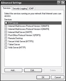
You can configure services to allow unsolicited traffic from the Internet to be forwarded by the ICF computer to the private network. For example, if you are hosting an HTTP Web server service and have enabled the HTTP service on your ICF computer, unsolicited HTTP traffic will be forwarded by the ICF computer to the HTTP Web server. A set of operational information, known as a service definition, is required by ICF to allow the unsolicited Internet traffic to be forwarded to the Web server on your private network. The Services tab of ICF is shown in Figure 18-2.
Figure 18-2: Services tab of ICF
In addition, you can add custom services to the Services tab of ICF. ICF can also perform port translation for incoming connections. When you create a custom service, you will need to specify the following:
Description of service Determines how the service is displayed on the Services tab
Name or IP address Determines the host name or IP address of the computer offering the service if the service is not hosted on the local computer
External port Defines the TCP or UDP port on the ICF computer that will listen to inbound traffic to the service
Internal port Defines the TCP or UDP port to which the ICF computer will forward the inbound traffic to the computer defined in the Name Or IP Address field
Communications that originate from a source outside the ICF computer, such as the Internet, are dropped by the firewall unless an entry in the Services tab is made to allow passage. ICF silently discards unsolicited communications, preventing common attacks, such as port scanning and NetBIOS enumeration. ICF can create a security log so you can view the activity that is tracked by the firewall. You can choose whether to log dropped, successful, or dropped and successful packets. By default, packets are logged to c:\windows\pfirewall.log. The log file has a default maximum size of 4098 KB. Table 18-7 describes the fields in the packet log file.
Table 18-7: Description of Information Logged by ICF
Field
Description
Date
Specifies date that the recorded transactions occurred in the format YY-MM-DD.
Time
Specifies time that the recorded transaction occurred in the format HH:MM:SS.
Action
Specifies which operation was observed by the firewall. The options available to the firewall are OPEN, CLOSE, DROP, and INFO-EVENTS-LOST. An INFO-EVENTS-LOST action indicates the number of events that happened but were not placed in the log.
Protocol
Specifies which IP protocol was used for the communication.
Src-ip
Specifies the source IP address of the computer attempting to establish communications.
Dst-ip
Specifies the destination IP address of the communication attempt.
Src-port
Specifies the source port number of the sending computer. Only TCP and UDP will return a valid src-port entry.
Dst-port
Specifies the port of the destination computer. Only TCP and UDP will return a valid dst-port entry.
Size
Specifies the packet size in bytes.
Tcpflags
Specifies the TCP control flags found in the TCP header of an IP packet:
ACK Acknowledgment field significant
FIN No more data from sender
PSH Push function
RST Reset the connection
SYN Synchronize sequence numbers
URG Urgent Pointer field
Tcpsyn
Specifies the TCP synchronization number in the packet.
Tcpack
Specifies the TCP acknowledgment number in the packet.
Tcpwin
Specifies the TCP window size in bytes in the packet.
Icmptype
Specifies a number that represents the Type field of the ICMP message.
Icmpcode
Specifies a number that represents the Code field of the ICMP message.
Info
Specifies an information entry that depends on the type of action that occurred. For example, an INFO-EVENTS-LOST action will create an entry of the number of events that happened but were not placed in the log since the last occurrence of this event type.