IEEE LAN Standards
| The job of developing LAN standards, which are occupants of the Data Link layer, was assumed by the IEEE Project 802 LAN/MAN Standards Committee (LMSC), which has developed a number of LAN standards, including those based on bus topologies and ring topologies. Two examples of the former are "Ethernet" (known as CSMA/CD[13] ) and "Token Bus," products of the IEEE 802.3 and IEEE 802.4 WGs, respectively. Wireless LANs based on standards defined by the IEEE 802.11 WG don't have a "topology" in the same physical sense as a wired LAN, but logically could be considered a bus. Actually, Token Bus is a hybrid technology, since although it is physically a bus, it is logically a ring. Examples of pure ring topologies include Token Ring, the product of the IEEE 802.5 WG, and Fiber Distributed Data Interface (FDDI[14] ), which was produced by ANSI X3T9.5.
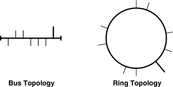
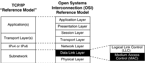
The IEEE LMSC's partitioning of the Data Link layer allows the LLC sub-layer to be independent of the details of the Physical layer, with a standardized interface to the MAC sub-layer. The MAC sub-layer protocol is typically paired with at least one type of Physical layer medium (many MAC sub-layer protocols can operate over more than one type of Physical layer medium). For example, Ethernet can run over many types of media that support baseband (digital) transmissions, including two types of coaxial cable, single-mode and multi-mode optical fiber, and twisted pair copper wire. An Ethernet PHY was also defined to allow operation over analog broadband media (specifically, a pair of closed circuit television channels), but that form of deployment (known as 10BROAD36) was never very popular. Even though FDDI was a product of the American National Standards Institute, and not the IEEE LMSC, it was designed such that it required the IEEE 802.2 LLC (and possibly SNAP) protocols for its proper operation. This is proof of the wide applicability of the IEEE LMSC model of Data Link protocols. So, ANSI X3T9.5 designed FDDI as a MAC sub-layer protocol that required LLC, despite the fact that FDDI was not a product of the IEEE LMSC. As of the late 1990s, FDDI became obsolete, since the necessary PHY components necessary to build FDDI "NICs" or FDDI interfaces for hubs (concentrators), switches, or routers were no longer produced. Faster technologies displaced FDDI; although it was one of the most reliable LAN technologies ever invented, it was never designed to scale up to gigabit speeds. Figure 2-6 illustrates the two basic LAN topologies. Each of the short line segments emanating from the bus or ring represents a single device attached to the LAN. In each case, one of the attachments is drawn as a longer, thicker line, which represents a link from this LAN segment to an intermediate device; for example, a bridge or router (or, if you prefer, a layer-2 or layer-3 switch). Note that in either case, the topology can easily support delivery of broadcast frames (special frames that may be received by every station on the medium), which is one key property that distinguishes LANs from point-to-point or point-to-multipoint WAN-oriented Data Link protocols. Figure 2-6. Bus and ring LAN topologies
In the course of defining its LAN-oriented (i.e., broadcast capable) Data Link layer protocols, the IEEE LMSC has divided the Data Link layer into two sub-layers, as follows. This logical subdivision of the Data Link layer is undetectable by adjacent layers.
The Data Link layer's job, in its entirety, is to ensure that the bit-transmission facility (or facilities) of a particular physical medium appears error-free to the Network layer. For media that are shared among multiple stations, the Data Link layer also specifies procedures by which the stations fairly share access to the medium. By "error-free" we mean that the Data Link layer only delivers frames up to the Network layer if they have passed some level of testing and been found to be free from errors. Ultimately, the responsibility for ensuring that the data is uncorrupted lies with the Application, which may use techniques such as strong cryptography to ensure that any data it receives is exactly what the sender intended. In order to determine if a frame has an error or not, most Data Link protocols compute simple but effective frame check sequences which allow the Data Link layer to certify that a frame is probably not corrupted, though most of the algorithms used for this purpose are capable of being fooled into accepting a frame that was modified en route. One reason is that the frame check sequence only protects a frame while it is on the wire, not when it is inside a switch being sent from one interface to another. If part of a frame was modified while it was inside a switch, the outgoing interface will compute a correct frame check sequence that reflects the new contents of the frame, and the receiver will not be able to tell if the frame check sequence is the same as that sent by the original sender. This is why the real responsibility for ensuring accuracy in data transport falls to a higher layer. Some Data Link layer technologies provide for reliable delivery via explicit acknowledgments (with retransmissions when necessary), or via forward error correcting codes, but LAN-oriented Data Link protocols tend to act in an "unreliable" mode. Due to the implicit lack of acknowledgments, this could also be called "unacknowledged" mode. Because Physical-layer errors are assumed to be quite rare in LAN media, and because the speeds are high and transmission latencies are low, it is reasonable to expect that higher-layer protocols can recover quickly based on the low rate of errors that are expected. The point-to-point or point-to-multipoint WAN-oriented Data Link protocols that pre-dated LAN technology had to cope with noisy lines. Due to the speed advantage enjoyed by LANs, it became more efficient to just send the data as quickly as possible, and recover from the occasional rare error, rather than to operate in a much slower "explicit acknowledgement" mode that was virtually guaranteed to be error-free. While LAN-oriented Data Link layer protocols are admittedly unreliable (actually, they are very reliable, if installed properly), unacknowledged Data Link layer protocols, such as those that are used over LAN media, do still retain at least an error-detecting code, so that the frames that are handed up to the Network layer are believed to be error-free. Typically, either the Network layer will have its own reliability mechanism(s), or the Network layer will punt the ultimate verification of the data's validity to the Transport layer or above. One reason for this shift of responsibility to a higher layer is that LAN media are typically so much faster and provide a significantly more robust transmission medium than did the older media that required low-layer reliability mechanisms. This latter statement is not strictly true in the context of wireless LANs, since the medium over which wireless LANs operate is not dedicated to their use, and interference from other sources may corrupt the frames that are "in flight" between WLAN stations. The MAC sub-layer protocol that has been defined for use in IEEE 802.11 WLANs has specific features that are designed to make the best of a challenging situation. Wired LAN and WAN media are now extremely reliable, as measured by bit error rates, but it is no longer the case that LAN media are implicitly faster than WAN media. Today, certain point-to-point WAN data circuits operate at SONET[16] OC-192 speeds, sending data at just less than 10 Gbps,[17] whereas common LAN speeds in early 2003 top out at "only" 1 Gbps (e.g., 1000BASE-T). A version of Ethernet known as IEEE 802.3ae has been defined that operates at 10 Gbps,[18] but it is not yet in common use (even in LAN backbones), and will probably not be used outside of WAN backbones for quite some time.[19]
|
EAN: 2147483647
Pages: 60
- The Four Keys to Lean Six Sigma
- Key #1: Delight Your Customers with Speed and Quality
- Key #4: Base Decisions on Data and Facts
- Making Improvements That Last: An Illustrated Guide to DMAIC and the Lean Six Sigma Toolkit
- The Experience of Making Improvements: What Its Like to Work on Lean Six Sigma Projects

