FCP Operational Details
| This section provides an in-depth exploration of the operational details of FCP. This section complements and builds upon the FCP overview provided in Chapter 4. You are also encouraged to consult the ANSI T11 FC-DA specification series to fully understand which combinations of FC and FCP features are permitted in real-world deployments. FCP Addressing SchemeFCP leverages the FC addressing scheme described in Chapter 5. No additional names or addresses are defined by the ANSI T10 FCP-3 specification. FCP Name Assignment and ResolutionName assignment for FCP devices and ports occurs as described in Chapter 5. For name resolution, FCP leverages the FCNS as described in Chapters 3 and 5. The FCP-3 specification suggests using a service-oriented approach during initial discovery of fabric attached devices. However, discovery behavior is not mandated by the FCP-3 specification. So, FCP devices may query the FCNS in a wide variety of ways. FCP devices may also leverage the ELS commands described in Chapter 5. FCP Address Assignment and ResolutionAddress assignment for FCP ports occurs as described in Chapter 5. No additional procedures or special requirements are defined by the FCP-3 specification. FCP Session EstablishmentUnlike iSCSI, FCP does not implement multiple session types, phases and stages. Instead of establishing a discovery session with the target device, FCP initiators establish a session with the FCNS to perform discovery operations. Likewise, targets establish a session with the FCNS. This session is long-lived and remains active until the initiator or target goes offline. Initiators establish the same type of FCP session with target devices to perform I/O operations. An FCP session is established with a simple two-way handshake. FCP processes establish communication via the process login (PRLI) ELS command defined in the FC-LS specification. Only initiators may send a PRLI Request. A single PRLI Request followed by a single LS_ACC ELS can establish a session between two FCP devices. Alternately, a single PRLI Request and a single LS_ACC ELS may be exchanged for the purpose of discovering the FCP operating parameters (called service parameters in FCP parlance) supported by a pair of FCP devices. In this case, another PRLI Request and another LS_ACC ELS are required to establish a session. Like iSCSI, some FCP service parameters are negotiated, and others are simply declared. Negotiated FCP parameters are called requirements, and all others are called capabilities. After a session is established, the relationship between the communicating FCP processes is called an image pair. An FCP image pair must exist before SCSI data transfer is permitted between FC devices. As with PLOGI, PRLI may be performed explicitly or implicitly. Only explicit PRLI is described in this book for the sake of clarity. Whereas iSCSI natively supports the exchange of all required operating parameters to establish a new session, FCP relies on SCSI for the exchange of certain service parameters. This is accomplished via the scsi mode sense and mode select commands. The mode sense command is used to discover the service parameters supported by a target device or logical units within a target device. The mode select command is used to inform a target device or logical units within a target device which service parameters to use. Because SCSI commands cannot be issued until after PRLI completes, the use of scsi mode commands to establish FCP service parameters requires modification of FCP session behavior after session establishment. The FCP-3 specification does not define how this modification should be accomplished. So, one of the logical unit device servers (usually LUN 0) must communicate scsi mode parameters to the FCP port(s) via proprietary means. This is handled within each SCSI device (no network communication). For more information about FCP's use of the scsi mode commands, see the FCP Login Parameters section of this chapter. For more information about FCP session establishment, readers are encouraged to consult the ANSI T10 FCP-3 and SPC-3 specifications, and the ANSI T11 FC-FS-2 and FC-LS specifications. FCP Data Transfer OptimizationsFCP does not support equivalent functionality to iSCSI phase-collapse for the final data-in information unit (IU) and SCSI status. However, FCP supports equivalent functionality to iSCSI phase-collapse for first burst data. Support for unsolicited first burst data is negotiated via PRLI, but PRLI does not support negotiation of the first burst buffer size. Therefore, the first burst buffer size must be negotiated using the SCSI MODE commands with the Disconnect-Reconnect mode page or via proprietary means. FCP does not support immediate data. For more information about FCP first burst optimization, readers are encouraged to consult the ANSI T10 FCP-3 and SPC-3 specifications. When DWDM or SONET is used to extend an FC-SAN, end-to-end latency can be sufficiently significant to affect performance. As a result, FC switch vendors and SAN extension vendors are responding with proprietary features that reduce round-trip delay in such environments. For example, FC switches produced by Cisco Systems can reduce round-trip delay for write data transfers via a feature called FC write acceleration (FCWA). FCWA provides local spoofing of the target signal (an FCP_XFER_RDY IU) that indicates readiness to receive write data. The switch at the remote site performs the necessary buffering to avoid dropped frames. Unlike the standardized FCP first burst optimization, FCWA operates on every data IU transmitted by an initiator. Another key difference in the behavior of these two optimizations is that FCWA does not eliminate the need for flow-control signaling, whereas unsolicited first burst data is sent without receiving a transfer request from the target. FCP IU FormatsIn FCP parlance, a protocol data unit is called an information unit. The FCP-3 specification defines five types of IU: FCP_CMND, FCP_DATA, FCP_XFER_RDY, FCP_RSP, and FCP_CONF. This section describes all five IUs in detail. This section also describes the details of the link services most commonly used by FCP. As discussed in Chapter 5, the FC specifications define many link services that may be used by end nodes to interact with the FC-SAN and to manage communication with other end nodes. Three types of link service are defined: basic, extended, and FC-4. Each basic link service (BLS) command is composed of a single frame that is transmitted as part of an existing Exchange. Despite this, BLS commands are ignored with regard to the ability to mix information categories within a single sequence as negotiated during PLOGI. The response to a BLS command is also a single frame transmitted as part of an existing Exchange. BLSs are defined in the FC-FS specification series. The BLS most commonly used by FCP is abort sequence (ABTS). As stated in Chapter 5, an ELS may be composed of one or more frames per direction transmitted as a single sequence per direction within a new Exchange. Most ELSs are defined in the FC-LS specification. The ELSs most commonly used by FCP include PRLI and read exchange concise (REC). An FC-4 link service may be composed of one or more frames and must be transmitted as a new Exchange. The framework for all FC-4 link services is defined in the FC-LS specification, but the specific functionality of each FC-4 link service is defined in an FC-4 protocol specification. The FCP-3 specification defines only one FC-4 link service called sequence retransmission request (SRR). This section describes the ABTS, PRLI, REC, and SRR link services in detail. FCP IUs are encapsulated within the Data field of the FC frame. An FCP IU that exceeds the maximum size of the Data field is sent as a multi-frame Sequence. Each FCP IU is transmitted as a single Sequence. Additionally, each Sequence composes a single FCP IU. This one-to-one mapping contrasts the iSCSI model. Fields within the FC Header indicate the type of FCP IU contained in the Data field. Table 8-10 summarizes the values of the relevant FC Header fields.
Only one of the members of an FCP image pair may transmit FCP IUs at any point in time. The sequence initiative (SI) bit in the F_CTL field in the FC Header controls which FCP device may transmit. To transmit, an FCP device must hold the sequence initiative. If an FCP device has more than one FCP IU to transmit, it may choose to hold the sequence initiative after transmitting the last frame of a Sequence. Doing so allows the FCP device to transmit another FCP IU. This is known as Sequence streaming. When the FCP device has no more FCP IUs to transmit, it transfers the sequence initiative to the other FCP device. During bidirectional commands, the sequence initiative may be transferred many times at intervals determined by the participating FCP devices. When an FC frame encapsulates an FCP_CMND IU, the Parameter field in the FC Header can contain a task identifier to assist command retry. If command retry is not supported, the Parameter field is set to 0. Command retry is discussed in the FCP Delivery Mechanisms section of this chapter. Unlike iSCSI, FCP uses a single command IU (FCP_CMND) for SCSI commands and TMF requests. Figure 8-16 illustrates the format of the FCP_CMND IU. Note that FCP IUs are word-oriented like FC frames, but the FCP specification series illustrates FCP IU formats using a byte-oriented format. This book also illustrates FCP IU formats using a byte-oriented format to maintain consistency with the FCP specification series. Figure 8-16. FCP_CMND IU Format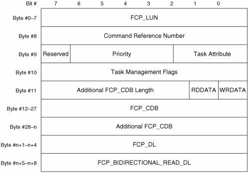 A brief description of each field follows:
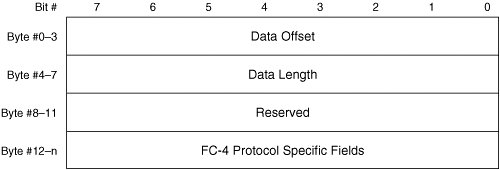
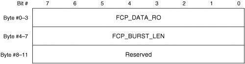
Unlike iSCSI, FCP uses a single IU (FCP_DATA) for both data-out and data-in operations. The only difference in IU format for data-out versus data-in operations is the manner in which the SI bit in the FC Header is handled. For data-out operations, the sequence initiative is transferred from initiator to target after transmission of each FCP_DATA IU. This enables the target to transmit an FCP_XFER_RDY IU to continue the operation or an FCP_RSP IU to complete the operation. For data-in operations, the sequence initiative is held by the target after transmission of each FCP_DATA IU. This enables the target to transmit another FCP_DATA IU to continue the operation or an FCP_RSP IU to complete the operation. For all FCP_DATA IUs, the Parameter field in the FC Header contains a relative offset value. The FCP_DATA IU does not have a defined format within the Data field of the FC frame. The receiver uses only the FC Header to identify an FCP_DATA IU, and ULP data is directly encapsulated in the Data field of the FC frame. An FCP_DATA IU may not be sent with a payload of 0 bytes. Note The FC-FS-2 specification mandates the Information Category sub-field of the R_CTL field in the FC Header must be set to solicited data even when the initiator sends unsolicited first burst data. When an FC frame encapsulates an FCP_XFER_RDY IU, the Parameter field in the FC Header is set to 0. In contrast to the iSCSI model, FCP implements a one-to-one relationship between FCP_XFER_RDY IUs and FCP_DATA IUs. The FC-FS-2 specification categorizes the FCP_XFER_RDY IU as a Data Descriptor. The FC-FS-2 specification also defines the general format that all Data Descriptors must use. Figure 8-17 illustrates the general format of Data Descriptors. Figure 8-18 illustrates the format of the FCP_XFER_RDY IU. Figure 8-17. Data Descriptor Format Figure 8-18. FCP_XFER_RDY IU Format A brief description of each field follows:
The final result of each SCSI command is a SCSI status indicator delivered in an FCP_RSP IU. The FCP_RSP IU also conveys FCP status for protocol operations. When an FC frame encapsulates an FCP_RSP IU, the Parameter field in the FC Header is set to 0. Unlike iSCSI, FCP uses a single response IU (FCP_RSP) for SCSI commands and TMF requests. Figure 8-19 illustrates the format of the FCP_RSP IU. Figure 8-19. FCP_RSP IU Format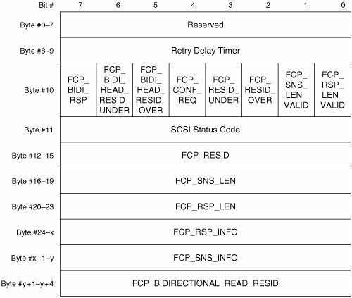 A brief description of each field follows:
The FCP_CONF IU is sent by an initiator only when requested via the FCP_CONF_REQ bit in the FCP_RSP IU. The FCP_CONF IU confirms the initiator received the referenced FCP_RSP IU. The target associates an FCP_CONF IU with the appropriate FCP_RSP IU via the FQXID. For all FCP_CONF IUs, the Parameter field in the FC Header is set to 0. The FCP_CONF IU does not have a defined format within the Data field of the FC frame. Additionally, the FCP_CONF IU has no payload. The target uses only the FC Header to determine a given FC frame is actually an FCP_CONF IU. The FCP_CONF IU is not supported for TMF requests. Similarly, the FCP_CONF IU is not supported for intermediate commands in a chain of SCSI-linked commands. For SCSI-linked commands, the FCP_CONF IU may be requested for only the last command of the task. The PRLI ELS is the explicit mechanism by which a session is established between two FCP devices. Support for PRLI is optional. PRLI is the primary, but not the only, mechanism by which service parameters are exchanged. Only initiators can send a PRLI. Possible responses to PRLI include LS_ACC and Link Service Reject (LS_RJT). PRLI and its associated responses are each encapsulated in the Data field of an FC frame. The fields in the FC Header indicate the payload is a PRLI, LS_ACC, or LS_RJT. Table 8-12 summarizes the values of the relevant FC Header fields. A single format is defined in the FC-LS specification for both PRLI and its associated LS_ACC. Figure 8-21 illustrates the format of PRLI and its associated LS_ACC. Figure 8-21. PRLI and Associated LS_ACC ELS Format
A brief description of each field follows:
Like iSCSI, FCP negotiates some service parameters, while others are merely declared. The FCP-3 specification defines the specific format of the PRLI Service Parameter Page. Figure 8-22 illustrates the FCP-specific format of the PRLI Service Parameter Page. Figure 8-22. PRLI Service Parameter Page Format for FCP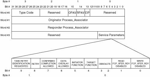 A brief description of each field follows:
In the absence of errors, the target responds to PRLI with LS_ACC. The FCP-3 specification defines the specific format of the LS_ACC Service Parameter Page. Figure 8-23 illustrates the FCP-specific format of the LS_ACC Service Parameter Page. Figure 8-23. LS_ACC Service Parameter Page Format for FCP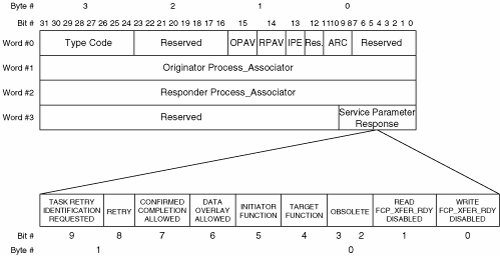 A brief description of each field follows:
If the PRLI is not valid, the target responds with LS_RJT. A single LS_RJT format is defined in the FC-LS specification for all ELS commands. Figure 8-24 illustrates the format of LS_RJT. Figure 8-24. LS_RJT ELS Format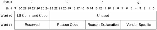 A brief description of each field follows:
The REC ELS enables an initiator to ascertain the state of a given Exchange in a target. Support for REC is optional. When an initiator detects an error (for example, a timeout), the initiator may use REC to determine what, if any, recovery steps are appropriate. Possible responses to REC include LS_ACC and LS_RJT. REC and its associated responses each are encapsulated in the Data field of an FC frame. The fields in the FC Header indicate the payload is a REC, LS_ACC, or LS_RJT. Table 8-16 summarizes the values of the relevant FC Header fields. If command retry is supported, the Parameter field in the FC Header contains the Task Retry Identifier of the Exchange referenced in the REC. If command retry is not supported, the Parameter field in the FC Header is set to 0. The formats of REC and its associated responses are defined in the FC-LS specification. Figure 8-25 illustrates the format of REC.
Figure 8-25. REC ELS Format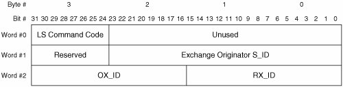 A brief description of each field follows:
In the absence of errors, the target responds to REC with LS_ACC. Figure 8-26 illustrates the format of LS_ACC sent in response to REC. Figure 8-26. LS_ACC ELS Format for REC ELS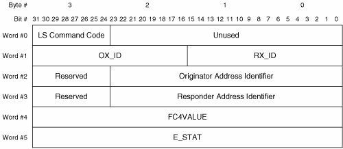 A brief description of each field follows:
If the REC is not valid, or if the target does not support REC, the target responds with LS_RJT. Figure 8-24 illustrates the format of LS_RJT. Table 8-14 summarizes the LS_RJT reason codes. Table 8-17 summarizes the reason explanations defined by the FC-LS specification that are relevant to REC. All reason explanations excluded from Table 8-17 are either irrelevant to REC or reserved.
The ABTS BLS enables an initiator or target to abort a sequence or an entire Exchange. As with all BLS commands, support for ABTS is mandatory. ABTS may be transmitted even if the number of active sequences equals the maximum number of concurrent sequences negotiated during PLOGI. Likewise, ABTS may be transmitted by an FCP device even if it does not hold the sequence initiative. This exception to the sequence initiative rule must be allowed because the sequence initiative is transferred with the last frame of each sequence, but the receiving device neither acknowledges receipt of frames nor notifies the sender of dropped frames (see Chapter 5). Thus, the transmitting device typically detects errors via timeout after transferring the sequence initiative. As a result, ABTS can be sent only by the device that sent the sequence being aborted. Each ABTS is transmitted within the Exchange upon which the ABTS acts. Moreover, the SEQ_ID in the FC Header of the ABTS must match the SEQ_ID of the most recent sequence transmitted by the device that sends the ABTS. In other words, a device may abort only its most recently transmitted sequence or Exchange. The sequence initiative is always transferred with ABTS so the receiving device can respond. The responding device may hold the sequence initiative after responding, or transfer the sequence initiative with the response. Possible responses to an ABTS include the basic accept (BA_ACC) BLS and the basic reject (BA_RJT) BLS. The action taken upon receipt of an ABTS is governed by the Exchange Error Policy in affect for the Exchange impacted by the ABTS. ABTS and its associated responses are each encapsulated in the Data field of an FC frame. The fields in the FC Header indicate that the payload is a BLS command or a BLS response. Table 8-18 summarizes the values of the relevant FC Header fields. Bit 0 in the Parameter field in the FC Header conveys whether the ABTS acts upon a single sequence (set to 1) or an entire Exchange (set to 0). The ABTS does not have a defined format within the Data field of the FC frame. Additionally, the ABTS has no payload. The ABTS recipient uses only the FC Header to determine that a given FC frame is actually an ABTS. The formats of the BA_ACC and BA_RJT are defined in the FC-FS-2 specification. A unique BA_ACC format is defined for each BLS command. Figure 8-27 illustrates the format of the BA_ACC associated with ABTS. Figure 8-27. BA_ACC Format for ABTS BLS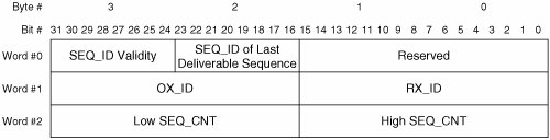
A brief description of each field follows:
A common BA_RJT format is defined for all BLS commands. Figure 8-28 illustrates the format of the BA_RJT. Figure 8-28. BA_RJT Format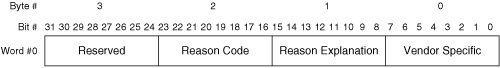 A brief description of each field follows:
The SRR link service enables an initiator to request retransmission of data during a read command, request that the target request retransmission of data during a write command, or request retransmission of the FCP_RSP IU during a read or write command. Only initiators may send an SRR. Support for SRR is optional. If SRR is supported by both initiator and target, REC and task retry identification also must be supported by both devices. The Parameter field in the FC Header contains the Task Retry Identifier of the Exchange referenced by the SRR payload. SRR may not be used during bidirectional commands. This limitation does not apply to iSCSI, which supports retransmission during bidirectional commands. The sequence initiative of the Exchange referenced by the SRR is always transferred to the target upon receipt of an SRR. This allows the target to transmit the requested IU. The sequence initiative of the SRR Exchange is also transferred to the target. Possible responses to SRR include the SRR Accept and the FCP Reject (FCP_RJT). The SRR and its associated responses are each encapsulated in the Data field of an FC frame. The fields in the FC Header indicate that the payload is an FC-4 link service request or an FC-4 link service response. Table 8-21 summarizes the values of the relevant FC Header fields. The formats of SRR and its associated responses are defined in the FCP-3 specification. Figure 8-29 illustrates the format of SRR.
Figure 8-29. SRR Link Service Format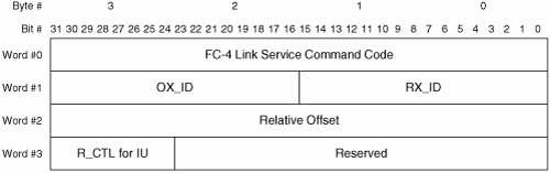 A brief description of each field follows:
In the absence of errors, the target responds to SRR with SRR Accept. Figure 8-30 illustrates the format of SRR Accept. Figure 8-30. SRR Accept Format A brief description of the field follows:
Upon receipt of an FCP_RJT, the initiator must abort the entire Exchange referenced by the SRR. Figure 8-31 illustrates the format of FCP_RJT. Figure 8-31. FCP_RJT Format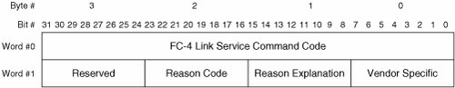 A brief description of each field follows:
The preceding discussion of FCP IU and FC link service formats is simplified for the sake of clarity. Comprehensive exploration of FCP IU and FC link service usage is outside the scope of this book. For more information, readers are encouraged to consult the ANSI T10 SAM-3, SAM-4, and FCP-3 specifications, and the ANSI T11 FC-FS-2 and FC-LS specifications. FCP Additional Login ParametersWhile most FCP service parameters are negotiated or declared via the PRLI mechanism described in the preceding section, some FCP service parameters are negotiated via the SCSI MODE SENSE and MODE SELECT commands. Detailed exploration of the SCSI MODE commands is outside the scope of this book, but readers should at least be aware of the service parameters that FCP negotiates via the SCSI MODE commands. So, this section provides a brief description of the service parameters relevant to FCP that are negotiated via the SCSI MODE commands. Three SCSI mode pages are relevant to FCP service parameter negotiation. They are the Disconnect-Reconnect mode page, the Protocol Specific Logical Unit mode page, and the Protocol Specific Port mode page. The Disconnect-Reconnect mode page is used to optimize performance between an initiator port and a target port. Three parameters are relevant to fabric-attached FCP devices: Maximum Burst Size, First Burst Size, and Data Overlay. The Maximum Burst Size is the maximum number of bytes that may be transferred in a single FCP_DATA IU. Because FCP mandates a one-to-one relationship between IUs and sequences, this parameter also determines the maximum number of bytes that may be transferred in a single sequence. However, this parameter might not equate to the maximum number of bytes transferred during a single possession of the sequence initiative, because sequence streaming is allowed. The First Burst Size is the maximum number of bytes that may be transferred in a single unsolicited FCP_DATA IU. This parameter is ignored if the WRITE FCP_XFER_RDY DISABLED bit in the PRLI Request or associated LS_ACC ELS is set to 0. Data overlay is negotiated via the enable modify data pointers (EMDP) bit. The EMDP bit overrides the value of the DATA OVERLAY ALLOWED bit in the PRLI Request. The Protocol Specific Logical Unit mode page as implemented by FCP is called the FC Logical Unit Control mode page. The FC Logical Unit Control mode page is used to configure certain logical unit service parameters. In particular, FCP implements the enable precise delivery checking (EPDC) bit. The EPDC bit enables or disables in-order command delivery (called precise delivery in FCP parlance). Unlike iSCSI, FCP does not mandate precise delivery. Instead, FCP allows precise delivery to be negotiated with each logical unit. The Protocol Specific Port mode page as implemented by FCP is called the FC Port Control mode page. The FC Port Control mode page is used to configure certain target port service parameters. For fabric-attached devices, FCP implements the sequence initiative resource recovery time-out value (RR_TOVSEQ_INIT). This timer determines the minimum amount of time a target port must wait for a response after transferring the sequence initiative. If this timer expires before a response is received, the target port may begin error recovery procedures. For more information about FCP's use of the SCSI MODE commands, readers are encouraged to consult the ANSI T10 SPC-3 and FCP-3 specifications. FCP Delivery MechanismsFCP leverages the delivery mechanisms implemented by FC. Additionally, the FCP-3 specification defines several mechanisms for detecting and recovering from errors. Like iSCSI, FCP supports error recovery at the task (Exchange) level and the IU (sequence) level. In other words, an FCP device may choose to abort each task affected by an error (suboptimal) or retransmit just the dropped IUs (optimal). The choice is subject to the Exchange Error Policy in effect for the Exchange affected by the error. Like iSCSI, FCP does not support frame level error recovery. However, iSCSI benefits from frame level retransmission as implemented by TCP, whereas FCP does not because FC does not support frame level retransmission (see Chapter 5). Error DetectionLike iSCSI, FCP mandates that both initiators and targets are responsible for detecting errors. Errors are detected via timeouts, FC primitives, FC Header fields, FCP IU fields, the ABTS BLS, and the REC ELS. Initiators and targets must be able to detect the link errors, protocol errors, and timeouts defined in the FC specifications. Additionally, initiators and targets must be able to detect protocol errors and timeouts using FCP IU fields. Last, initiators and targets must be able to accept and process the ABTS BLS as a means of error detection. The only error detection mechanism that is optional is the REC ELS. Exchange Level Error RecoveryThe initiator is responsible for performing error recovery, but the target may optionally invoke recovery action under certain conditions. At the Exchange level, the error recovery procedure is called Recovery Abort. Recovery Abort is defined in the FC-FS-2 specification. The FCP-3 specification defines rules for using Recovery Abort. Recovery Abort is used to abort an Exchange and to recover the associated resources within the initiator and target devices. All initiators must be able to invoke Recovery Abort. All targets must be able to execute Recovery Abort in response to initiator invocation. Recovery Abort may be invoked in response to an error or by a TMF request. When Recovery Abort is invoked, the SCSI application client must reissue the aborted SCSI task. If the target detects a frame error, the target discards all frames associated with the Exchange. The target takes no further action and waits for the initiator to detect the error via timeout. Upon detecting an error (via timeout or otherwise), the initiator optionally sends a REC to the target. If the REC confirms that an error has occurred, or if the initiator chose not to send a REC, the initiator sends an ABTS to the target. Bit 0 in the Parameter field in the FC Header is set to 0 indicating that the scope of the ABTS is the entire Exchange. The target takes the necessary internal actions to ensure the affected logical unit is notified. The target then responds with a BA_ACC. The Last_Sequence bit in the F_CTL field in the FC Header of the BA_ACC must be set to 1 (to terminate the Exchange). Upon receiving the BA_ACC, the initiator begins the R_A_TOV timer and notifies the SCSI application client. The SCSI application client may then reissue the command. Upon expiration of the R_A_TOV timer, the initiator sends an RRQ to the target. The RRQ enables reuse of the counter values covered by the Recovery Qualifier. When the initiator receives an LS_ACC in response to the RRQ, the Recovery Abort procedure is complete. If the initiator does not receive an LS_ACC in response to the REC within two times the R_A_TOV, the REC exchange is aborted via Recovery Abort. The REC may be retried in a new exchange, or the initiator may choose to send an ABTS without retrying REC. If the initiator does not receive a BA_ACC within two times the R_A_TOV, the initiator may send another ABTS. If the second BA_ACC is not received within two times the R_A_TOV, the initiator must explicitly logout the target. The initiator must then perform PLOGI and PRLI to continue SCSI operations with the target, and all previously active SCSI tasks must be reissued by the SCSI application client. Sequence Level Error RecoveryInitiators and targets are not required to support sequence level error recovery. Sequence level error recovery involves the abortion of a single sequence and the retransmission of the missing data. Upon detecting an error (via timeout or otherwise), the initiator optionally sends a REC to the target. If the REC confirms an error has occurred, or if the initiator chose not to send a REC, the initiator sends an ABTS to the target. Bit 0 in the Parameter field in the FC Header is set to 1, indicating that the scope of the ABTS is a single sequence. The target discards all frames associated with the sequence identified by the ABTS. The target then responds with a BA_ACC. The Last_Sequence bit in the F_CTL field in the FC Header must be set to 0. Upon receiving the BA_ACC, the initiator sends an SRR. Upon receiving the SRR, the target responds with an SRR Accept. The target then retransmits the requested data. In the case of a write command, the SRR requests an FCP_XFER_RDY IU that requests the missing data. The SEQ_CNT field in the FC Header of the first frame of retransmitted data is set to 0 even if continuously increasing SEQ_CNT is in affect for the connection. Note the retransmitted data can be (and often is) transferred from a relative offset that was already used in the Exchange being recovered. This is allowed even if the DATA OVERLAY ALLOWED bit is set to 0 during PRLI. If the initiator does not receive an LS_ACC in response to the REC within two times the R_A_TOV, the REC exchange is aborted via Recovery Abort. The REC may be retried in a new exchange, or the initiator may choose to send an ABTS without retrying REC. If the initiator does not receive a BA_ACC within two times the R_A_TOV, the initiator may send another ABTS. If the second BA_ACC is not received within two times the R_A_TOV, the initiator must explicitly logout the target. The initiator must then perform PLOGI and PRLI to continue SCSI operations with the target, and all previously active SCSI tasks must be reissued by the SCSI application client. If a BA_ACC is received, but the initiator does not receive an SRR Accept within two times the R_A_TOV, both the SRR Exchange and the Exchange being recovered must be aborted via Recovery Abort. FCP IU Boundary DetectionBecause each FCP IU maps to a single sequence, IU boundaries can be easily detected via the SEQ_ID field in the FC Header. The SEQ_ID field is present in the FC Header of every FC frame, so IU boundaries can be detected even when one or more frames are dropped. So, FCP does not require a message synchronization scheme. This contrasts with the iSCSI model. FCP In-Order Command DeliveryLike iSCSI, FCP supports in-order command delivery (precise delivery). Unlike iSCSI, precise delivery is optional for FCP devices. Another key difference is the scope of enforcement. Whereas iSCSI enforces in-order command delivery for all commands between each initiator-target pair, FCP enforces precise delivery on a per-LUN basis. The initiator sends an FC Logical Unit Control mode page to each LUN that is discovered by the report luns command. For each LUN that responds with the EPDC bit set to 1, commands are delivered in-order. In practice, the enforcement difference is purely academic because most modern storage arrays support precise delivery on all LUNs for performance reasons. However, the per-LUN nature of precise delivery has a real effect on the way FCP implements command numbering. A separate CRN counter is maintained for each LUN that supports precise delivery. In other words, a CRN counter is implemented per I_T_L nexus. Note The order of command delivery does not necessarily translate to the order of command execution. The order of command execution can be changed via TMF request as specified in the SCSI standards. The CRN field is set to 0 in every FCP_CMND IU that conveys a TMF request regardless of whether the LUN supports precise delivery. Likewise, the CRN field is set to 0 in every FCP_CMND IU that conveys a SCSI command to LUNs that do not support precise delivery. By contrast, the CRN field contains a value between 1 and 255 in each FCP_CMND IU that conveys a SCSI command to LUNs that support precise delivery. The CRN counter for a given LUN is incremented by 1 for each command issued to that LUN. However, certain SCSI commands (such as inquiry and test unit ready) do not require precise delivery and may be assigned a value of 0 for the CRN field even when issued to LUNs that support precise delivery. When the CRN counter reaches 255, the value wraps back to one for the next command. The limited number range of the CRN counter exposes FCP devices to possible ambiguity among commands in environments that support sequence level error recovery. State information about each Exchange and sequence must be maintained for specific periods of time to support retransmission. Eventually, the initiator will issue a new command using an OX_ID that was previously used within the session. If the target is still maintaining state for the old command associated with the reused OX_ID, the target could confuse the two commands. To mitigate this risk, task retry identification must be implemented. The Task Retry Identifier effectively extends the CRN counter by providing an additional identifier for each command. The Task Retry Identifier must be consistent in all IUs and link services related to a single command (FCP_CMND, REC, SRR). Note In high I/O environments, the limited CRN counter might seem to pose a risk to performance. However, each LUN uses a separate CRN counter, which effectively mitigates any risk to performance by increasing the total CRN address space. In the unlikely event that an initiator needs to issue more than 255 ordered commands to a single LUN before the first command completes, the CRN counter limit would prevent issuance of the 256th command. However, when so many commands are simultaneously outstanding, it indicates that the LUN cannot execute commands as quickly as the application requires. Thus, the LUN is the performance bottleneck, not the CRN counter. FCP Connection and Session RecoveryFCP does not support stateful connection or session recovery. If a connection fails, FCP notifies the SAL of the I_T nexus loss, and all state related to the connection and session is cleared. The initiator must perform PLOGI and PRLI to continue SCSI operations with the target, and all previously active SCSI tasks must be reissued by the SCSI application client. If a session fails, FCP notifies the SAL of the I_T nexus loss, and all state related to the session is cleared. The initiator must perform PRLI to continue SCSI operations with the target, and all previously active SCSI tasks must be reissued by the SCSI application client. The preceding discussion of FCP delivery mechanisms is simplified for the sake of clarity. For more information about FCP delivery mechanisms, readers are encouraged to consult Chapter 5 and the ANSI T10 FCP-3 specification. |

EAN: 2147483647
Pages: 196