3.4 UML-F presentation tags
3.4 UML-F presentation tags
The basic UML-F tags introduced in the following sections deal only with the visual representation of elements they do not define any properties of the annotated modeling elements.
3.4.1 Completeness and abstraction
Frameworks tend to have large numbers of classes and interfaces. A complete class diagram that shows all classes and interfaces, as well as their relationships, can easily become incomprehensible and overloaded. Thus, class diagrams usually show only the relevant aspects. In other words, a diagram normally presents information about the existence of elements in a system. However, typically there are other elements that have been omitted in a particular view. Two class diagrams that show the same class with different attributes are not to be considered inconsistent since they might just highlight different aspects of the system structure. In general, the structural part of the architecture of a framework can be captured by one class diagram (or a small number of them) that shows only the essential classes of the framework. The subclasses of a larger class hierarchy, auxiliary classes, and parts of aggregated classes may be omitted in these architectural descriptions.
As visibility, multiplicity, and role names are attachments to other class diagram elements, their omission is obvious missing types for attributes and methods can also be detected. However, omitted classes, interfaces, associations, attributes, and methods are not as readily apparent. Standard UML provides the ellipsis (' ') to mark omissions of attributes and methods. However, we also find it useful to be able to mark elements as complete. Therefore, we propose the UML-F tag ' ' to mark completeness and the tag ' ' to explicitly mark incompleteness.[6] In accordance with standard UML, the ' ' tag is the default. This means that class diagrams and all their elements are considered incomplete unless explicitly marked as complete via use of ' '.
[6] The proposed marker ' ' and the further application of marker ' ' extend standard UML. They have been used successfully by the authors for many years. Neither is framework-specific and can therefore be used independently of the rest of UML-F for any kind of UML modeling.
Figure 3.5 shows three representations of class Human. The first is complete, whereas the second omits an attribute and the third omits the attribute compartment as well as the method compartment. We can mark the attribute and the method sections as complete and incomplete independently of each other. Each of the sections may be empty and still be marked as complete, denoting that there are no entries required.
Figure 3.5. Three representations of the same class
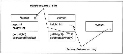
To clarify the use of these markers, let us distinguish three levels of models: the system itself, the UML model of the system, and the diagrammatic representation of that model on the screen, on paper, or on a white board. The latter representation is often also called a view. The two markers ' ' and ' ' provide information about the relationship between the view (for example, on a screen) and the UML model we are working on. This is in contrast to most of the other UML-F tags which express information about the relationship between the model and the system.
These markers are necessary to allow the description of a system using incomplete views. Thus we call ' ' and ' ' presentation markers as they are used for presentation purposes. They do not indicate, for example, whether or not a class is extensible. Furthermore, it may be the case that a superclass is shown completely, whereas its subclasses may have only incomplete attribute or method lists.
Table 3.3 summarizes the semantics of the completeness tags. Formally, both markers can be seen as graphical shortcuts for a Boolean tag complete , denoting complete=True and complete=False .
| Tag form | Applies to | Description |
|---|---|---|
| Class | The graphical representation of the class contains a complete list of all attributes and methods. | |
| Interface | The graphical representation of the interface contains all methods and constants of the interface. | |
| Attribute list | The list of attributes is complete. | |
| Method list | The list of methods is complete. | |
| Object | Analogous to class. | |
| Set of links belonging to an association or composition | The object diagram shows all links of that association/composition. | |
| Generalization | The generalization shows all existing direct subclasses. | |
| Association | All information about this association is listed in the diagram. | |
| Class, interface, attribute list, method list, generalization, association | Inverse of : the graphical representation may be incomplete (but may also be complete we simply don't know). |
3.4.2 Flat and hierarchical representation of classes and expanded class views
This section introduces a notation for a graphical representation of hierarchical and flat views of classes. This is particularly useful in the context of framework representations. Thus, we incorporate it as a UML-F extension to the UML standard. We regard this notation as an extension of the visual representation of a class. It allows us to denote quite intuitively the signature of a class, namely its public and non-public methods. Furthermore, one class may have several different representations. One view might show the class in its hierarchical context; another shows all inherited methods and attributes in a flat form.
In this UML-F extension, a small box represents a method or attribute graphically. If the method or attribute is protected or private, the small box is drawn completely inside the class boundary; if it is a public method or attribute, the corresponding box crosses the border of the class, denoting that it is accessible from outside (see Figure 3.6).
Figure 3.6. Hierarchical (a and b) and flat (c) representation of class Employee
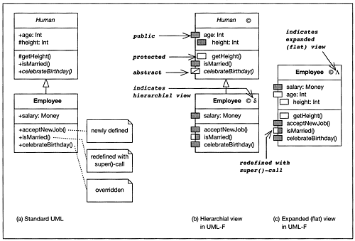
UML-F introduces the class marker 'd' as a tag that denotes a hierarchical view, which shows only the difference between a class and its direct superclass.[7] For expanded lists of attributes and methods, UML-F provides the symbol '?'.[8] As a default, we assume that classes are represented hierarchically ('d'), where only the differences from the particular superclass(es) are shown. This is consistent with the UML standard presentation of classes. Figure 3.6 demonstrates several variants of representing class Employee: Figure 3.6(a) shows the standard UML representation, and Figures 3.6(b) and (c) apply the UML-F extensions in a hierarchical and flat context respectively.
[7] Hence the Greek lower case letter delta (d) for difference.
[8] The Greek upper case letter lambda (?) denotes a list, but its iconic shape also resembles the inheritance hierarchy where the listed methods come from.
In addition, UML-F introduces a graphically more enhanced representation for individual methods. UML-F allows the representation of methods with a gray or unfilled rectangles to show whether a particular method has been (re-)defined.
 An unfilled rectangle expresses that the method is inherited and not redefined such as method getHeight() in class Employee. In superclasses we use this marker if it is irrelevant whether a method is newly defined or inherited.
 A gray rectangle indicates that the method is either newly defined, or is inherited but completely redefined (methods acceptNewJob() and celebrateBirthday() demonstrate this).
 A half-gray/half-unfilled rectangle denotes that the method is redefined but uses the inherited method through a super()-call (e.g. method isMarried() in class Employee). Thus the inherited code is augmented by new code pieces.
 A rectangle with a diagonal line indicates that the method is abstract and needs to be overridden in subclasses.
The unfilled and the gray rectangles, marking inheritance ![]() and a new definition
and a new definition ![]() , apply to attributes as well. As attributes are neither abstract nor overridden, the other two markers do not apply to instance variables.
, apply to attributes as well. As attributes are neither abstract nor overridden, the other two markers do not apply to instance variables.
In the expanded version of a class representation ('?'), one cannot see in which class a method was actually defined. If desired, we may therefore augment the method name with a class path, e.g. Human.getHeight() in Java format, or Human::getHeight() in C++ style. The proposed markers are sufficient to denote the situations for the object structures presented in this book. However, tools that are capable of roundtrip engineering could offer additional features, such as subcompartments of the instance variable or method sections indicating in which class it is defined (see Figure 3.7(a)).
Figure 3.7. Alternatives to extend markers for more details on the hierarchy
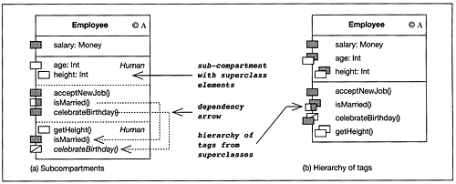
Another variant would be to stack the markers from superclasses behind the direct marker. Figure 3.7(b) shows the markers from superclass Human right behind the direct markers of the class.
To summarize the UML-F class (hierarchy) presentation tags, UML-F introduces two tags, 'd' and '?', to denote hierarchical and flat representations of classes and objects, as well as unfilled and gray rectangles to denote overriding and inheriting of methods. Table 3.4 summarizes the use of the tags.
| Tag | Applies to | Description |
|---|---|---|
| d | Class, interface | The graphical representation of the class only lists attributes and methods that are introduced or redefined in that class, but not the inherited properties. This is the difference between this class and its superclass. |
| ? | Class, interface | The graphical representation of the class lists inherited methods and attributes as well as newly introduced or refined methods and attributes. |
The application of the two tags 'd' and '?' is orthogonal to applying the completeness tags ' ' and ' '.
Four inheritance indicators apply to methods and attributes. They are represented by unfilled and gray rectangles to express the overriding and inheriting of methods. Table 3.5 summarizes these tags.
| Tag | Applies to | Description |
| | Method, attribute | A method implementation is inherited and not overridden or newly defined, and an attribute is inherited or newly defined. |
| | Method, attribute | A method is newly defined or overridden. The class provides the complete code for the method. An attribute is newly defined. |
| | Method | The method is overridden, but the superclass method is called (for example, through a super()-call in Java). |
| | Method | The method is abstract and has to be overridden in subclasses. |
All the tags introduced here can also be represented in UML standard form by using the Boolean tag expanded with the value false for 'd' and true for '?'. The inheritance indicator symbols can be represented in the same way by a textual tag inherited .
3.4.3 UML-F extensions of the object diagram notation
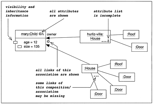
Just like class diagrams, object diagrams can represent abstractions of actual object structures in the system. Therefore, the markers ' ' and ' ' are useful for characterizing their completeness or incompleteness. An object state is defined by the attributes of its class, including not only the directly given attributes but also the inherited ones. Therefore, the flat and hierarchical representations indicated by the markers '?' and 'd' for classes apply equally well to attributes in object diagrams.
Figure 3.8 shows an object diagram extended by UML-F markers. These markers are mostly carried over from class diagrams in a straightforward way. However, completeness and incompleteness markers are also used to describe whether the set of given links is complete. Marker ' ' on the two links called owner of the Mary object indicates that all links belonging to that association and concerning the Mary object are shown. The incompleteness marker ' ' instead denotes that her second house (the anonymous one) has at least three doors, but may have more. Omitted markers mean incompleteness by default.
Figure 3.8. Sample object diagram with UML-F extensions
The following sections introduce a number of concepts that allow additional markings of classes, associations, and the composition relationship for different purposes. As a rule of thumb, these concepts are also useful in the context of object diagrams as well. They apply to an object if they apply to an object's class. The same holds true for links and their respective associations or composition relationships.
3.4.4 Tags for sequence diagrams
Sequence diagrams are an intuitive and appealing means of describing desired interaction sequences. However, they have some drawbacks. Like object diagrams, they denote objects that may not actually exist, since the system can have a completely different structure at runtime. Even if the objects exist as described in the sequence diagram, the denoted interaction may still not occur at runtime. There may be alternative paths of interaction, for example in order to handle an error or because of a different configuration of the participating objects.
Furthermore, the interaction behavior of an object often depends on its attribute values. For example, Boolean values may govern whether a certain interaction does or does not happen. Finally, the sequence diagram may describe the reaction of the system to an action that will never occur, such as a specific user input.
Due to the exemplary nature of a sequence diagram, the described interaction may occur many times, repeatedly involving the same objects or involving different object structures each time. In recursive object structures, it may even happen that the interaction is stacked. In concurrent systems, different threads may exhibit the same interaction sequence in parallel.
The examples above corroborate that UML sequence diagrams are necessarily incomplete because a sequence diagram can neither capture all objects of a system, nor cover the complete lifetime of the system in all its details and all its branches. Instead, it focuses on a subset of the existing objects, during an interval in time, and on one branch only. Furthermore, it disregards irrelevant messages within this time interval, even though these messages are sent or received by one of the objects depicted in the diagram. A sequence diagram tells a story that stresses certain aspects, but removes irrelevant details. Sequence diagrams are an abstraction of actually occurring sequences of method invocations. Thus, producing appropriate sequence diagrams often requires a solid understanding of the overall behavior.
As we have already described, the reaction of a method invocation can depend on the current state of the objects and the environment. To describe variable behavior, the current UML standard provides control techniques to overcome the limited expressiveness of such exemplary sequence diagrams. Among others, these control techniques cover:
guards
repetition
alternatives
optional method calls
referencing.
Many of these techniques closely resemble the control structures of programming languages (see Table 3.6).
| Sequence diagram construct | Corresponding programming construct | Explanation |
|---|---|---|
| Repetition | While-do constructs | A message (or a sequence of messages) occurs repeatedly. |
| Alternative with or without guard | If-then-else and case constructs | Two (or more) variants of interactions exist. |
| Optional part | Guarded command: if Test then X | A message (or message sequence) may be omitted. |
| Referencing | Method invocation | If the diagram becomes too complex, then a subdiagram can be used to describe a subinteraction in the same way that operations can be decomposed within subroutines. |
However, some subtle differences exist. In a program being a constructive executable description the while-do constructs must describe their termination conditions, and alternatives must be guarded by an if-then-else condition. A sequence diagram instead is a descriptive constraint on the possible behavior of the system. This is an analogy to class diagrams that are constraints on possible object structures. Therefore, sequence diagrams may, for example, describe repetitions that define no explicit termination condition.
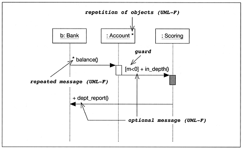
A guard, as defined in standard UML, is denoted as a condition in square brackets, such as [m < 0] in Figure 3.9. A guard discriminates alternatives. Only if a guard condition is true does the guarded interaction occur. Using a guard does not necessarily specify what happens if the guard is not satisfied. In particular, another behavior, possibly specified by another sequence diagram, may occur.
Figure 3.9. Repetition, guards, and optional messages
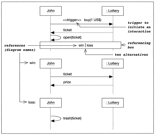
Guards are particularly useful in combination with alternatives, when two guards cover all possibilities. Alternatives allow the description of different paths of interaction. They can describe two different reactions to a method invocation that can occur. Alternatives can, but need not, have a guard attached in order to discriminate which alternative will be taken. If the guards are missing, or they overlap, it is left to the implementer to choose which variant the system should follow. The UML standard way of describing alternatives within a single sequence diagram becomes awkward to read and understand easily. Thus, UML-F offers another way of describing alternatives in combination with referencing that allows the structuring of sequence diagrams in a crisper and clearer manner (see Figure 3.10).[9]
[9] The UML-F solution to presenting alternatives in sequence diagrams is not an additional concept but just a different form of presentation.
Figure 3.10. Alternatives and referencing in sequence diagrams in UML-F
Optional parts describe whether a certain method invocation happens at all. If, for example, an observer gets the notice from its observable that the values have changed, the observer may fetch the new values. However, if the observer is an element of a GUI and is currently not visible on the screen, the fetch method call might be omitted or deferred. In UML-F, a '+' sign is used to describe that a message is optional. For example, the in_dept() method in Figure 3.9 is optional and the guard specifies when it is issued. The method dept_report(), sent from the Scoring department to the Bank, is also optional but the specification of an associated condition is left open.
If a certain single or compound interaction occurs repeatedly within a sequence diagram, the repetition mechanism is used. To denote repeated messages, UML-F introduces the '*' sign.[10] An interval such as (2 5), used instead of '*', may constrain the minimum and maximum number of repetitions. For example, a pin number for an automated teller machine may be entered 1 3 times. A repetition factor of 0 1 is equal to being optional, '+', and the repetition factor 1 is redundant.
[10] Both the optional '+' sign and he repetition sign '*' stem from regular expressions within the Backus Naur notation. In sequence diagrams they are used for the very same purpose, namely extending the expressiveness of a sequence diagram from describing one exemplar interaction sequence to branching sets of possible sequences.
Because multiple messages are often sent to multiple objects, UML-F also allows the attaching of the repetition marker '*' to an object. In Figure 3.9 several :Account objects exist. Each of these objects is activated through one of the multiple method calls that are labeled balance(), and each reacts individually. If desired, a guard on the multiple method call may select a subset of objects that receive the message.
As stated above, a sequence diagram quickly tends to become overloaded with too many details. Thus, a technique for factoring common behavior into subsequence diagrams is useful. Other diagrams can reference these subsequence diagrams. This allows a structured view of interaction sequences and provides a way to reuse common interactions in different diagrams. To do this, it is necessary to identify sequence diagrams by name. Figure 3.10 exemplifies the referencing of two subsequence diagrams that describe alternative behaviors. Combinations of the operators described above are possible for example, by attaching a repetition operator to a reference box the repetition of a whole sequence of messages can be described.
In practice, many sequence diagrams are used in a trigger mode. In a triggered sequence diagram, the first method invocation causes the rest of the interaction to happen. In the sequence diagrams above, the first message serves as a starting point for the interaction pattern to occur. We introduce the marker trigger to indicate that a message on the sequence diagram triggers the rest of the interaction.
To summarize the use of UML-F sequence diagram tags sequence diagrams are the primary means of describing interactions between objects. A limited use of sequence diagrams can be found in Gamma et al. (1995) to illustrate interactions between the participating components of a pattern.
The form of sequence diagrams presented here affords improved expressiveness compared with sequence diagrams in standard UML. However, as sequence diagrams have to cope with two dimensions structure and time there are a number of interactions that still cannot be described: unordered messages, the explicit destroying of objects, and so on.[11] We have presented a subset of UML sequence diagrams augmented with techniques that prove particularly useful for describing interactions in frameworks. They include the use of boxes for referencing, '*' for repetition of objects and interactions, '+' for optional interactions, the trigger marker, and a new way of presenting alternatives. Table 3.7 summarizes these tags. The ideas for these extensions largely stem from approaches on augmentation of message sequence charts (MSC) and their unification with the UML, partly described in its standardization documents (ITU-TS, 1999) and Kr ger (2000). They have not (yet) been integrated with the UML standard and are therefore regarded as UML-F specific extensions.
[11] There is a clear trade-off between the complexity of a notation and its ease of use. Unfortunately, there is no optimal solution and individuals have different preferences ranging from 'nice-to-have' to 'essential'. This conflict shows up in all UML notations but becomes more apparent in behavior notations, such as sequence diagrams.
| Tag | Applies to | Description |
|---|---|---|
| * | Message | The message can be repeated as often as desired. Zero occurrences are allowed. |
| * | Object | The object can exist multiple times (including zero). Typically, the denoted objects are the target of a repeated message arrow. |
| + | Message | The message is optional, occurring at most once. |
| (A B) | Message | A more concise way to describe multiple occurrence of a message (here between A and B times). |
| trigger | Message | If the first message in a sequence diagram causes the subsequent interaction to occur, then it is called a trigger. |
Of course, the use of '+' and (A B) can be extended to objects as well. The use of references within sequence diagrams cannot be described as a standard UML tag extension. This, instead, is a so-called 'heavyweight' extension of UML since it directly affects the abstract syntax (the meta-model)
EAN: 2147483647
Pages: 84