| With the skeleton in place, you could now bind the character to the skeleton if you wanted. However, at this point, the skeleton has only Forward Kinematics (FK) linkages. This means that to animate the skeleton, you must start at the root and work your way to the end of the chain. For example, if a character is going to pick up a remote control, you would animate the torso leaning over, then the bicep extending, and then the forearm's rotation, and hope that the hand could approach wherever the remote control is placed (see Figure 12.7). For much character animation, this approach is cumbersome and results in awkward character animation. However, for other animations, FK is sometimes a better choice for example, if a character is bowling and the arm needs to rotate freely in an arc. Maya provides tools for setting a key so that you can toggle between FK and IK animation for a joint. Figure 12.7. Adjusting arm position with IK versus FK. 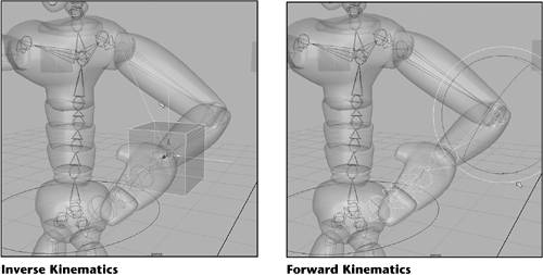
Returning to the example of picking up a remote control, IK accomplishes this animation the other way around. You would simply position the hand (now the end effector) over the remote control, and the body from the shoulder forward would bend in whatever way is necessary to reach the remote control. As you can imagine, IK might cause ridiculous contortions as it places the two ends of the skeleton chain to seek a "solution" for posing the character. There are a variety of ways to set up IK so that certain joints take precedence and are moved before other joints. You can also set joint preferences and limits so that knees don't bend backward and bend only to their natural limits, for example. You can also set limits and resistance levels so that as one joint nears its defined rotational limit, more of the required rotation is applied to other joints. IK in Maya comes in three types: Rotate Plane This IK type is best for joint chains in which individual joints tend to rotate within a plane, even though the plane itself might rotate. Think of it as starting at a ball joint, but using hinges for the remaining joints. The animator is free to set the plane orientation with this IK type. For example, the shoulder might change rotation to set the rotate plane for the forearm and bicep, but the forearm and bicep always rotate within this plane. Using Rotate Plane IK, you directly control the rotate plane orientation in the previous example, the shoulder rotation. You use Rotate Plane IK for typical arms and legs. Single Chain This IK type is similar to Rotate Plane in that the starting joint is a ball joint, free to rotate in all directions. However, instead of allowing the animator to pose the Rotate Plane for remaining joints, the Single Chain type poses all the joints according to how the IK is set up. Joints within the chain can have absolute limits beyond which they stop rotating, as well as "damping," in which the joint begins to resist rotation, transferring the rotation to other joints to achieve the pose. In any case, the joint setups determine how Maya poses joints between the start and end joints of the IK chain. Spline This unique type of IK is designed for more serpentine joint chains it's ideal for bullwhips, tentacles, and tails. A NURBS curve serves as the handle, and joints are repositioned as you modify the original curve.
In the next tutorial, you add IK to the character's arms and legs and add some rings around the character's hands and feet to make it easy to select and move these appendages. Tutorial: Setting Up Inverse Kinematics In this tutorial, you add IK handles and control objects to the skeleton. These handles and control objects enable you to control the position of the entire body by pulling on the simple objects that control the end effectors the hands and feet. On the DVD  Chapter_12\ch12tut02.wmv |
Toggle visibility off for the marionette mesh so that you can work directly with the skeleton. Switch to the Top view so that you can see from the character's right shoulder to right wrist. Choose Hotbox | Skeleton | IK Handle Tool | option box to open the IK Handle Tool Settings dialog box, and reset the settings. The Current Solver is set to ikRPsolver. This is the Rotate Plane solver, which works well for bicep-forearm relationships in which the limb bends within a plane that is, the forearm and bicep are "hinged" and rotate around one axis only. Therefore, the bicep-forearm combination rotates within one plane at all times. Close the dialog box. On the DVD  Chapter_12\ch12tut01end.mb |
tip Inverse Kinematics works with three types of solvers to create realistic motion: the Rotate Plane solver, the Single Chain solver, and the Spline solver. Solvers look at the position of joints to determine the best way to move them, based on the end effector's position, which is placed at the end of the IK chain you have applied the solver to. On the character's right arm, click on the shoulder joint (the ball at the end of the joint, not the linkage), followed by the wrist joint. An IK handle should appear. Switch to Move mode (hotkey: w) and reposition the IK handle that appears at the wrist to test it. Note that the movement stays within a plane defined by the white "pointer" in the circle that appears at the shoulder, as shown in Figure 12.8. This orientation is caused by creating the IK handle in the Top view. Undo your moves with the hotkey z. In the Channel Box, rename the IK handle as IKrighthand. Figure 12.8. The Rotate Plane IK handle keeps bicep-forearm motion in the plane indicated by the white pointer at the shoulder. 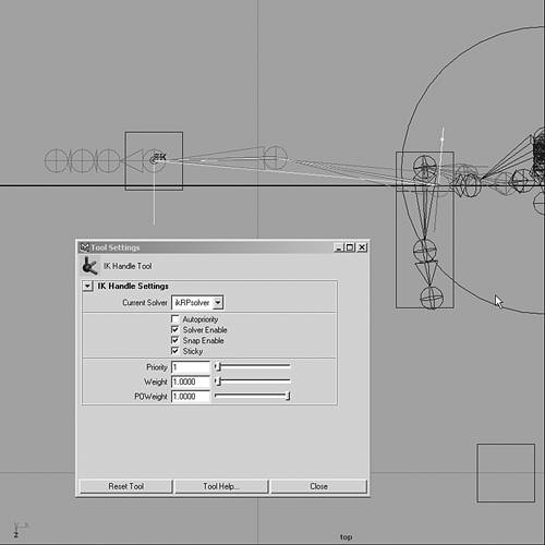
Next, you set the arm's IK pose to be the preferred angle. This is important for proper IK animation when creating bones, usually you want to have them slightly bent in the angle they would naturally bend in. Then, you can set this bend as the preferred angle for the IK chain. For the right arm, simply hold down the RMB over the IK handle, which should still be selected. When the marking menu appears, drag over the Set Preferred Angle option. Switch to the Top view and repeat steps 1 and 2 for the character's left arm, connecting shoulder to wrist with the IK Handle tool. Rename the IK handle as IKlefthand and set the pose as the preferred angle. Now, do a little character rigging: Create a Polygon box with Hotbox | Create | Polygon Primitives | Cube. Name the cube Right_Hand. Use the Move tool and snap the cube's center to the wrist's end effector (hotkey: v). In the Channel Box, change the Scale settings to 0.2, 0.2, and 0.2. While RightHand is selected, open the Attribute Editor (Hotbox | Window | Attribute Editor; hotkey: Ctrl+a). In the RightHandShape tab, open the Render Stats section. Clear all the check boxes to ensure that these objects do not render. This setting makes selection and animation easier. Duplicate the cube with Hotbox | Edit | Duplicate | option box (hotkey: Ctrl+d), reset the settings, and click Duplicate. Name the duplicate LeftHand. Use the Move tool and press the v key again to snap the new cube to the opposite wrist. Shift-select both boxes, and freeze their transforms with Hotbox | Modify | Freeze Transformations. This sets the Channel Box values back to their original settings. Therefore, you can easily set the character back to its original pose by setting the Translate and Rotate values to zero for each controller object. Add these box control objects to the Controllers layer you created in the first tutorial. Select the IK handle named IKrighthand (use the Outliner if you have trouble selecting it). Now, Shift-select the Right_Hand box in the Perspective view, and choose Hotbox | Edit | Parent | option box. Make sure the Preserve Position check box is selected, and click Parent. You should see that Ikrighthand now follows the Right_Hand box. Test this by selecting the cube and moving it, as shown in Figure 12.9 (don't forget to undo to place the object back after the test). Repeat these steps for IKlefthand and the Left_Hand box, making sure to select the parent (which is the box) last, before using the hotkey p to parent. Figure 12.9. Testing the box as a hand controller. 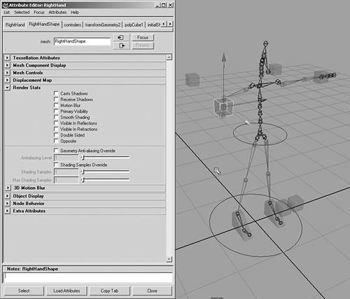
You need more control of the arm to keep the elbow facing in the correct direction. First, create another cube and use the Move tool along with the v hotkey to snap it into position. Place the new cube at the skeleton's right elbow. Copy the cube and place it at the left elbow also. In the Channel Box, decrease the Translate Z setting by -1 for each cube. Name the cube behind the left elbow LeftElbow and the cube on the right RightElbow. Select RightElbow and Shift-select ikHandleRThand. To constrain the elbow to these two new cubes, use Hotbox | Constrain | PoleVector | option box and click Apply. The default weight of 1 should be fine. Repeat this process for LeftElbow, Shift-selecting ikHandleLThand and constraining the PoleVector on the left side. Next, you add IK to the legs, using the same technique: building control boxes at each knee to easily constrain the knees in the correct direction during animation. Switch to the Perspective view. Choose Hotbox | Skeleton | IK Handle Tool | option box to open the IK Handle Tool Settings dialog box (much the same as in step 1 for the arm IK). The "+" cursor indicates that you should now apply IK to a joint chain. Click the hip joint of the left leg, and then click the ankle joint. The IK handle appears. Name this IK ikLeftLeg. Move the IK handle around to see its effect on the leg. Then, use undo (hotkey: Ctrl+z) to return the IK to its original position. Repeat step 8 for the right leg. Then, select each IK handle, right-click over the handle, and choose Set Preferred Angle. This option keeps the legs bending along this angle when you raise the knees. Make boxes to control the feet and knees: Create a polygon cube with Hotbox | Create | Polygon Primitives | Cube. Using the Channel Box, set Translate X, Y, and Z to 0.14, .105, and -0.147, and Scale X, Y, and Z to 0.2, 0.2, and 0.5. The cube should now be around the character's left foot. To make sure you know which control object is the foot while animating, right-click and select Vertices. Adjust the vertices to resemble a block foot shape, as shown in Figure 12.10. Name the cube LeftFoot. Figure 12.10. Testing the leg IK and control boxes. 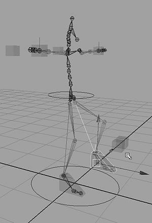
Duplicate the cube with Hotbox | Edit | Duplicate. Name the duplicate to RightFoot. Change the Translate X value to -0.14 for this duplicated cube. Shift-select both boxes, and freeze their transforms with Hotbox | Modify | Freeze Transformations. Add the two cubes to the Controllers layer, and disable the options in the Render Stats section of the Attribute Editor's shape node, as in step 4 for the hand's control boxes. Select the IK handle named IKrightleg (use the Outliner if you have trouble selecting it). Shift-select the RightFoot cube and parent (hotkey: p). Repeat these steps for IKleftleg and the LeftFoot cube. Test the control boxes and the IK by selecting each cube and moving it, as shown in Figure 12.10, and then undo your moves, or set the Translate X, Y, Z values in the Channel Box back to zero. Unhide the MarionetteLayer layer, and try moving the object handles again to observe how the skeleton is positioned within the character. To control the knees, use the same method as with the feet: Create a box (Hotbox | Create | Polygon Primitives | Cube). Using the Channel Box, set Translate X, Y, and Z to -0.325, 2, and 2, and Scale X, Y, and Z to 0.2, 0.2, and 0.2. The cube should now be positioned at waist height, but lined up in front of the marionette's right knee. Name the cube RightKnee. Select both knee controllers and freeze their transforms (Hotbox | Modify | Freeze Transformations). Next, add the knee controllers to the Controllers layer. Duplicate the RightKnee and change the Translate X value to 0.325 for this duplicated cube. Name this new cube LeftKnee. To constrain the RightKnee, select it and Shift-select ikRightLeg. Use Hotbox | Constrain | PoleVector | option box, and click Apply. Repeat this process for the LeftKnee, Shift-selecting ikLeftLeg and constraining the PoleVector on the left side. Select the RightFoot and use the Channel Box to change the Translate X setting to 0.28. Now do the same for the LeftFoot, changing the Translate X setting to 0.28. This should position the skeleton's legs and feet inside the Marionette. Notice that the feet are pointing outward because of the knee control. Move the LeftKnee controller in to -0.24 in the Translate X axis. Then, move the RightKnee in to 0.24. Freeze the knee and feet controllers again. Last, add a selection ring to the waist and connect it to the skeleton's root joint. Create a NURBS circle (Hotbox | NURBS Primitives | Circle). Set the circle's Translate Y to 2, and its Scale settings to 0.45, 0.45, and 0.45. Rename the circle as Waist. Assign it to the Controllers layer, and then freeze the transform with Hotbox | Modify | Freeze Transformations. Select any joint of the character. Because the joints are automatically created as a hierarchy, you can traverse the skeleton by pressing the up- and down-arrow keys, as with other grouped or parented objects. Press the up-arrow key until the entire skeleton is selected. Shift-select the circle, and parent the skeleton to the circle (hotkey: p). Select the circle and test the effect on the skeleton when the circle is moved, as shown in Figure 12.11. (Note: You should undo after you're finished testing to get the character back to its neutral pose.) This circle will be helpful when shifting the body's center of mass during an animation. Figure 12.11. Testing the waist circle handle. 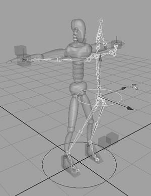
Select the two knee controllers and the two elbow controllers, and then Shift-select the Waist ring last. Parent these controllers to the waist (hotkey: p) to make sure the knee controllers are in front of the legs at all times and require less individual keyframing (see Figure 12.11). The elbow controllers now follow the rig. This keeps the feet and legs from flipping if they pass the controller during animation. With the legs and arms moving properly, you can now attach the skin to the skeleton. Note that you can add IK to any joint at any time, even after you attach the skin. In this chapter, however, you're progressing directly through character setup so that you don't have to go backward to make adjustments. The hands, feet, and waist control objects make it easier to animate the character later.
|