| The first step to setting up a character is to build its skeleton. With Maya's Joint tool, you can build skeleton chains directly. Where skeletons split, as in the head and arms that connect to the spine, you can build separate chains and connect them afterward. You can also build them all at once if you want. A key consideration when building a skeleton is the root joint. It's the "trunk" of the skeleton's tree, and all joints are affected by manipulation of the root joint. Usually the root joint is placed at the character's center of gravity; for bipeds, it's the pelvis. Tutorial: Adding a Skeleton In this tutorial, you set up the skeleton's joints and position them within the character's geometry in preparation for skinning. First, you create the skeleton's arms, legs, and spine, and then connect them to form a complete skeleton. The root joint of the skeleton will be the base of the spine, at the pelvis. On the DVD  Chapter_12\ch12tut01.wmv |
When you load the scene file noted next to the DVD icon, you'll see a low-resolution model of a character. It was modeled using the same techniques in Chapter 5, "Modeling with Polygons," but the smoothed mesh is not present. You'll work with this lower polygon version to keep interactivity fast, and you can apply a smooth to the character after the animation is in place. Also, notice that the character is posed in a typical "bind pose" arms horizontally outstretched from each side, legs slightly spread, head forward. This character position facilitates skeleton binding. On the DVD  Chapter_12\ch12tut01begin.mb |
Create a new layer and name it MarionetteLayer. Select a piece of the character mesh, press the up arrow to select the entire mesh group, and assign it to the MarionetteLayer layer. If you need to hide the Marionette mesh later, you can simply click on the V in the Layers dialog box to toggle visibility for this layer. Create another layer and name it Skeleton, and then create one more layer and name it Controllers. tip The Degrees of Freedom control that angles the joint rotates in. Setting it specifically for some joints, such as fingers, ensures that movement takes place only in natural or realistic directions. After all, a finger can bend in only one direction front to back. To create the character's left leg skeleton first, choose Hotbox | Skeleton | Joint Tool | option box to open the Tool Settings dialog box for joint settings. Make sure all the X, Y, and Z check boxes for the Degrees of Freedom setting are selected, as in Figure 12.1. Click Close to close the dialog box and switch to the Side view. The "+" cursor indicates that you're ready to create joints. Click at the pelvis center point, and then click at the hip (top of thigh), then the knee, and then the ankle. Next, click where the ball of the foot would be, and then the tips of the toes. Press Enter to finish creating this joint chain. Figure 12.1. The joint options in the Tool Settings dialog box. 
tip As with drawing a curve, you can use the Backspace key to delete the last joint only, rather than the entire joint chain. As with a curve drawing, you can also use the MMB to adjust the position of a joint you just placed. Next, you need to adjust the joint size to make it easy to view and select. You can control this setting in the Preferences dialog box, but it's easier to adjust by choosing Hotbox | Display | Joint Size | Custom to open the Joint Display Scale dialog box. Joints do not appear in renderings; they are like other manipulators in Maya. Simply scale them to a size that fits inside the mesh but is still easy to select, as shown in Figure 12.2. For this scene, 0.08 is used, but in a new scene, use the slider in the Joint Display Scale dialog box to determine your joint size initially. Figure 12.2. Adjusting joint display size. 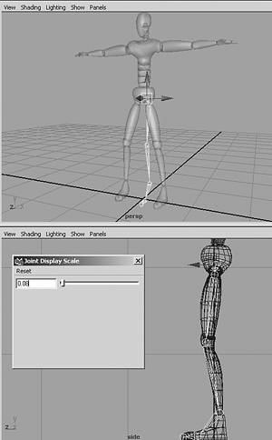
To move the leg chain into position under the left leg, first select the thigh joint in the Front view. While it's selected, copy this joint chain from the thigh joint down. Press the hotkey w to move the new chain to the right under the marionette mesh's leg. Translate the left leg in the x-axis to 0.06 and the right leg to 0.06. Switch to the Side view to create the spine joints, starting at the navel (just above the hip joint, which is referred to as the "root" from this point on), and then place the joints between each section of the torso and at the chest center point. Then, place a joint at the base of the neck, between each section of the neck into the base of the head, and finally at the top of the head. Press the hotkey y to complete this joint chain and start making another. In the Front view, create the character's right-arm skeleton next, starting with a joint slightly above the shoulder joint. Next, holding down the Shift key, place the shoulder joint of the arm, then the elbow, then the wrist, then the top of the palm, then the base of the fingers, and then the tips of the fingers. Take care that the joints are horizontal through the arm (see Figure 12.3 later in this tutorial). Press Enter to complete this chain. Figure 12.3. Mirroring the joints. 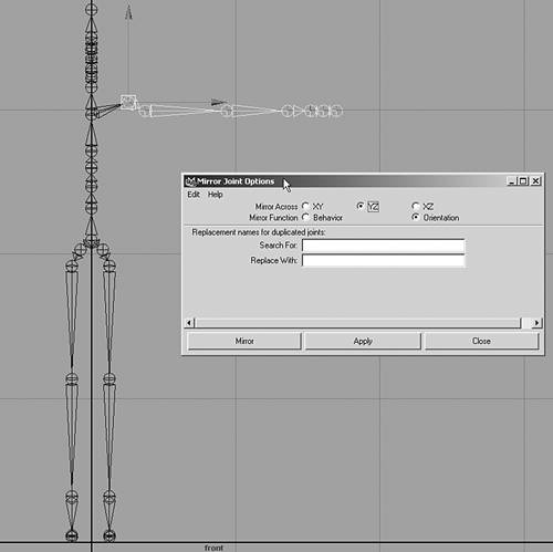
tip Be careful to place the arm joints for each arm so that they're level. If the joints aren't level, or horizontal, their preferred angle will be incorrect. The preferred angle of the arm should allow the elbow to bend in the z-axis. You'll place the bend for the elbow manually to make sure the correct angle is achieved. This step is necessary when placing the arm's Inverse Kinematics later in this chapter. Toggle visibility off for the MarionetteLayer layer. Select the left-shoulder joint, and then Shift-select the joint at the center of the chest. Parent the shoulder joint to the spine (hotkey: p). The left arm should now connect to the spine. Next, select the first shoulder joint and choose Hotbox | Skeleton | Mirror Joint | option box. In the Mirror Joint Options dialog box, select the YZ radio button for the Mirror Across setting and click Apply. Check that the arm has been copied in the correct position onto the right side of the Marionette; you might not want to close the dialog box until you're sure the arm is positioned correctly. The skeleton should look like Figure 12.3. tip Sometimes, it's not clear which direction is correct, so leaving the dialog box open makes more sense. Should the first direction you choose, say YZ, be incorrect, you can simply undo (hotkey: Ctrl+z) and select another of the three directional options. Select the navel joint, Shift-select the root, and parent these joints. The skeleton is now one connected linkage, as shown in Figure 12.4. The root joint moves the entire skeleton, which you can observe if you select the pelvis and move it. Figure 12.4. All the skeletal joints are created. 
Next, adjust joint placement. You built the skeleton in the Side and Front views, so the knees and elbows must be moved into a bent setting. Turn the MarionetteLayer layer's visibility on, switch to the Top view, and move (hotkey: w) each arm's elbow joint back slightly in the z-axis direction so that they're within the marionette mesh. The Translate Z setting should be at 0.096. To ensure you have the preferred angle in the arm's joint chain, select both wrist joints and move them forward slightly in the z-axis to 0.01. In the Front view, select the left hip joint. All joints below the hips are highlighted in green to indicate that they move with the selected joint. Switch to Move mode (hotkey: w). Move the hips apart till the upper-thigh joints are centered in the crease between the hip and the thigh. Repeat this step for the left hip. Be sure to set both hips to the same value in the Channel Box. The Translate X setting should be 0.06 and the negative value (-0.06) for the opposite side. Select the base of the spine and name it root. Then, select the left hip joint and Shift-select the root. Repeat this step for the right hip. Both legs should now be part of the entire skeleton. Select the joint at the base of the spine where you'll set the skeleton's root in the hierarchy. Choose Hotbox | Skeleton | Reroot Skeleton. Switch into the Side view so that you can add the jawbone joint. Select the Joint Tool with Hotbox | Skeleton | Joint Tool, and click once at the chin. Now, connect it to the spine just above the base of the skull: Shift-select the mouth joint on the spine, and parent it to the neck joint at the base of the skull. The joint connects to the spine, as shown in Figure 12.5. It's a good idea to add these bones before binding the skeleton to the skin because adding bones after that stage can sometimes cause problems. Figure 12.5. Adding a joint for the jaw. 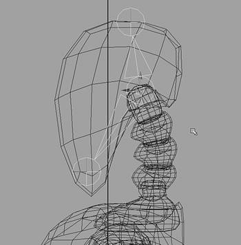
At this point, examine the final skeleton placement. Notice that you haven't placed the leg chains into the marionette yet. They will be moved into their final position after IK has been applied in the next section. Sometimes, it's easier to see the skeleton if you switch the display to X-Ray shading, as shown in Figure 12.6. Figure 12.6. Setting the display with Shading | Shade Options | X-Ray lets you see through the marionette mesh to the skeleton below. 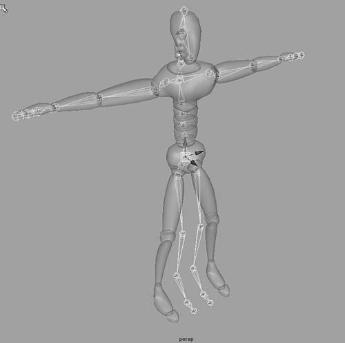
tip To turn on the X-Ray function and see into an object, at the top of your viewport, simply choose Shading | Shade Options and select the X-Ray option, which leaves a checkmark beside it to indicate that it's in use. Your skeleton is now in place, but you've probably noticed that the joints move freely through space. In the next tutorial, you add some Inverse Kinematics (IK) behavior to the limbs so that they rotate in a controlled way.
|