Connecting Shapes in Flowcharts
Flowcharts are the ideal diagrams for visually representing business processes. For example, if you need to show the flow of a custom-order process through various departments within your organization, you can use a flowchart. Visio includes several different flowchart templates; however, the most common type of flowchart uses simple shapes to represent the basic elements in a business process, as shown in the following table.
|
Shape Name |
Shape |
What It Represents |
|---|---|---|
|
Process |
|
Steps in a business process |
|
Decision |
|
Decisions in a business process |
|
Document |
|
Steps that result in or require documentation |
|
Data |
|
Steps that require data |


Tip
As you drag a flowchart shape onto the drawing page, a dynamic grid appears as a dotted line through the shape to show you how to align it with respect to the shapes already on the page.
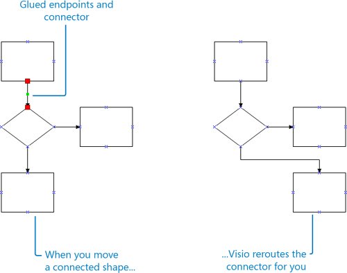
You add connectors between these flowchart shapes to show relationships between them and the sequence of steps in a process. Flowchart connectors are usually lines with arrowheads that can include text to clarify the process being depicted. When Visio adds a connector (or you add one yourself), the endpoints of the connector glue to the shapes it connectsthat is, Visio creates a bond that won't break unless you move a connector endpoint or delete the connector. When you select a connector that is glued to a shape, the connector's endpoints turn red, indicating that the connector will be rerouted when you move the connected shapes.
The method you use to connect shapes in a flowchart determines how the connectors reroute and how much control you have over where connectors are attached to shapes. If you simply connect one shape to another without specifying a point of connection, you don't have any control over how the connectors reroute, which is preferable for many diagram types. However, when you need total control over your shape connections, you can connect shapes using connection pointsspecific points on a shape represented by a blue x symbol. That way, the connector stays connected to those specific points, regardless of where you move the shapes.
Visio provides several methods for connecting shapes. Each method offers different levels of control, and some are more suited for particular drawing types, as shown in the following table. When you work with Visio, you typically use a combination of these methods when creating your diagrams.
|
Connection Method |
How To Use It |
When To Use It |
|---|---|---|
|
AutoConnect shapes by dragging a shape onto the drawing page |
Drag a shape onto another shape on the drawing page, and when blue arrows appear around the shape on the drawing page, position the shape over one of the arrows. |
Use this method when you want Visio to connect, align, and evenly distributes the shapes for youall in one step. Example diagram types: Any diagram that shows relationships, such as basic flowcharts, cross-functional flowcharts, or audit diagrams. Level of control: When you don't care exactly where two shapes connect to each other, how the connectors reroute, and the exact position of the connected shapes. |
|
AutoConnect shapes by clicking a shape on a stencil |
Click a shape on a stencil, and then position the pointer over a shape on the drawing page. When blue arrows appear around the shape on the drawing page, click one of them. |
Use this method when you want Visio to automatically connect shapes for you and you want to rapidly connect multiple shapes. Example diagram types: Any diagram that shows relationships, such as basic flowcharts, cross-functional flowcharts, or audit diagrams. Level of control: When you don't care exactly where two shapes connect to each other, how the connectors reroute, and the exact position of the connected shapes. |
|
AutoConnect neighboring shapes that are already on the drawing page |
Pause the pointer over a shape on the drawing page, and when blue arrows appear around the shape, move the pointer over the blue arrow closest to the neighboring shape to which you want to connect. The blue arrow turns dark blue, a red box appears around the neighboring shape to which you can connect, and a Connect to Neighboring Shape ScreenTip appears. Click the blue arrow to connect the two shapes. |
Use this method when you want to connect neighboring shapes that are already on the drawing page. Example diagram types: Any diagram that shows relationships, such as basic flowcharts, cross-functional flowcharts, or audit diagrams. Level of control: When you don't care exactly how the connectors reroute. |
|
Connect shapes as you drag them onto the page using the Connector tool |
Click the Connector tool, and then drag shapes onto the drawing page. Each new shape is connected to the selected shape on the drawing page. |
Use this method when you want to connect new shapes to the selected shape on the drawing page. Example diagram types: Any diagram that shows relationships, such as basic flowcharts, cross-functional flowcharts, or audit diagrams. Level of control: When you don't care exactly where two shapes connect to each other and how the connectors reroute, but you do want to precisely position the connected shapes. |
|
Connect shapes already on the drawing page using the Connector tool |
Position the pointer over a shape on the drawing page, and then drag to another shape to draw a connector between the two shapes. Or, position the pointer over a shape's connection point, and then drag to another shape's connection point to draw a connector between two shapes. |
Use this method when you want to connect shapes that are already on the drawing page. Example diagram types: Basic flowcharts and data flow diagrams. Level of control: This method gives you control over the precise point of connection between two shapes, if you connect the shapes using their connection points. |
|
Connect shapes that are already on the drawing page using the Connect Shapes command |
Hold down the Shift key, select all the shapes you want to connect, in the order you want to connect them, and then on the Shape menu, click Connect Shapes. |
Use this method when you want to connect shapes that are already on the drawing page in a specific order. Example diagram types: Any diagram that shows relationships, such as basic flowcharts, cross-functional flowcharts, audit diagrams, fault-tree analysis diagrams, and work flow diagrams. Level of control: When you don't care exactly where two shapes connect to each other or how the connectors reroute. |
|
Connect shapes already on the drawing page by using a connector from a stencil |
Drag a connector from a stencil onto the drawing page, position one endpoint on a connection point on one shape, and then position the other endpoint on the connection point on the other shape. |
Use this method in diagrams that use specific types of connectorsfor example, a 3-D arrow in block or ITIL diagram and network equipment in racks. Example diagram types: Basic, block, brainstorming, cause and effect, charts and graphs, ITIL, network diagrams, and value stream maps. Level of control: This method gives you control over the precise point of connection between two shapes. |
Important
The next section of this chapter covers different types of connections, connection points, and how to reroute connectors in more detail.
In this exercise, you start a new diagram based on the Basic Flowchart template. You use AutoConnect and the Connector tool so that Visio draws connectors and connects the shapes in your flowchart for you. You add text to the shapes and connectors to indicate a yes or no decision.
|
1. |
Start Visio. On the Template Categories list, click Flowchart. |
|
2. |
Under Featured Templates, double-click Basic Flowchart. |
|
3. |
From the Basic Flowchart Shapes stencil, drag a Process shape onto the drawing page and position it near the top of the page. |
|
4. |
From the Basic Flowchart Shapes stencil, drag a Document shape onto the drawing page, position it over the Process shape, position it over the bottom blue arrow that appears below the Process shape, and then release the mouse. 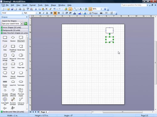
|
|
5. |
On the Basic Flowchart Shapes stencil, click the Decision shape. |
|
6. |
Pause the pointer over the Document shape on the drawing page until blue arrows appear around the shape, and then click the bottom blue arrow. |
|
7. |
On the Basic Flowchart Shapes stencil, click the Document shape. |
|
8. |
Pause the pointer over the Decision shape on the drawing page until blue arrows appear around the shape, and then click the bottom blue arrow. 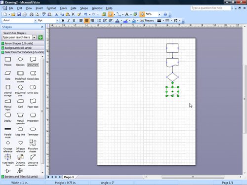
|
|
9. |
Select the Decision shape on the drawing page. |
|
10. |
On the Standard toolbar, click the Connector Tool button. Connector Tool
|
|
11. |
From the Basic Flowchart Shapes stencil, drag another Process shape onto the drawing page and position it to the left of the bottom Document shape. 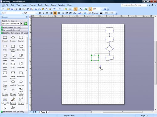
Tip Visio can number the shapes in your flowchart for you. To specify the numbering settings, on the Tools menu, point to Add-Ons, point to Visio Extras, and then click Number Shapes. |
|
12. |
From the Basic Flowchart Shapes stencil, drag a Decision shape onto the drawing page and position it below the Process shape you just added to the drawing page. |
|
13. |
From the Basic Flowchart Shapes stencil, drag a Document shape onto the drawing page and position it to the below the Decision shape you just added to the drawing page. |
|
14. |
On the Standard toolbar, click the Pointer Tool button. Pointer Tool
|
|
15. |
From the Basic Flowchart Shapes stencil, drag a Document shape onto the drawing page and position it to the left of the Document shape you just added to the drawing page. Tip You can use the dynamic grid to align the two shapes. |
|
16. |
On the Standard toolbar, click the Connector Tool button. |
|
17. |
Pause the pointer over the last Decision shape you added to the drawing page until a red box encloses the shape. 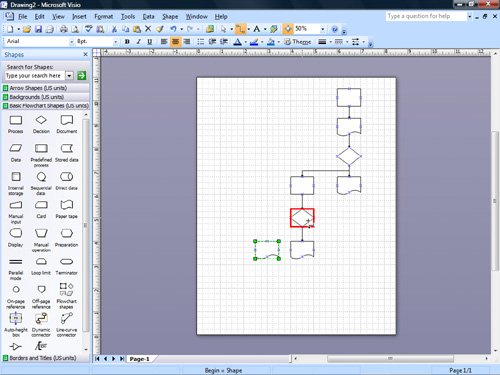
|
|
18. |
Drag to the last Document shape you added to the drawing page until a red box encloses that shape, and then release the mouse. 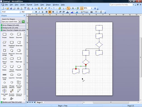
|
|
19. |
On the Standard toolbar, click the Pointer Tool button. |
|
20. |
Click the top Process shape to select it. |
|
21. |
Hold down |
|
22. |
With the top Process shape selected, type Receive Exhibitor Request. 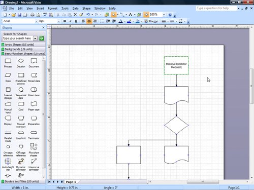
|
|
23. |
Select the next Document shape, and type Send Application. |
|
24. |
Select the next Decision shape, and type Qualify?. |
|
25. |
Select the next Document shape that's below the Decision shape, and type Send Denial. |
|
26. |
Select the Document shape that's to the left of the previous Document shape, and type Forward Application to Tradeshow Coordinator. 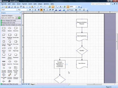
|
|
27. |
Select the connector that connects the previous Qualify? shape to the Forward Application to Tradeshow Coordinator shape. 
|
|
28. |
Type Yes. |
|
29. |
Select the connector that connects the previous Qualify? shape to the Send Denial shape, and then type No. 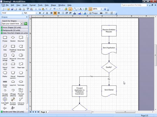
|
|
30. |
Click the pasteboard to deselect the connector. |
|
31. |
On the File menu, click Save As to open the Save As dialog box. |
|
32. |
In the File name box, type ConnectFlowchart, and then click the Save button to save the flowchart. |


 and left-click the top Process shape to zoom in on it.
CLOSE the ConnectFlowchart file.
Quick Reference
Getting Started with Visio 2007
- Getting Started with Visio 2007
- Starting Diagrams by Using Templates
- Working Within the Visio Environment
- Customizing the Visio Environment
- Getting Visio and Diagram Help
- Key Points
Adding Shapes to Diagrams
- Adding Shapes to Diagrams
- Working with 1-D and 2-D Shapes
- Adding Text to Shapes and the Drawing Page
- Moving, Sizing, Rotating, and Copying Shapes
- Working with Groups
- Finding Shapes for Diagrams
- Inserting Pictures into Diagrams
- Key Points
Formatting Shapes and Diagrams
- Formatting Shapes and Diagrams
- Formatting Individual Shapes
- Adding Decorative Elements to Diagrams
- Applying Themes to Entire Diagrams
- Key Points
Connecting Shapes
- Connecting Shapes
- Connecting Shapes in Flowcharts
- Modifying Shape Connections
- Changing the Layout of Connected Shapes
- Key Points
Creating Project Schedules
- Creating Project Schedules
- Creating Timelines to View Projects at a Glance
- Exporting Timelines to Create Gantt Charts
- Tracking Project Details with Gantt Charts
- Key Points
Creating Organization Charts
- Creating Organization Charts
- Importing Data to Create Organization Charts
- Storing and Displaying Employee Information in Organization Charts
- Customizing the Layout of Organization Charts
- Key Points
Laying Out Office Spaces
- Laying Out Office Spaces
- Creating Scaled Office Spaces
- Adding Door, Window, and Furniture Shapes to Office Layouts
- Organizing Shapes in Office Layouts by Using Layers
- Key Points
Creating Network Diagrams
- Creating Network Diagrams
- Connecting Shapes in Network Diagrams
- Storing Information with Network Shapes
- Creating Network Reports
- Key Points
Glossary
About the Authors
Choose the Right Book for You
EAN: 2147483647
Pages: 81
