Contention-Based Data Service
The additional features incorporated into 802.11 to add reliability lead to a confusing tangle of rules about which types of frames are permitted at any point. They also make it more difficult for network administrators to know which frame exchanges they can expect to see on networks. This section clarifies the atomic exchanges that move data on an 802.11 LAN. (Most management frames are announcements to interested parties in the area and transfer information in only one direction.)
The exchanges presented in this section are atomic, which means that they should be viewed as a single unit. Two distinct sets of atomic exchanges are defined by 802.11. One is used by the DCF for contention-based service; those exchanges are described in this chapter. A second set of exchanges is specified for use with the PCF for contention-free services. Frame exchanges used with contention-free services are intricate and harder to understand. Since very few (if any) commercial products implement contention-free service, these exchanges are not described.
Frame exchanges under the DCF dominate the 802.11 MAC. According to the rules of the DCF, all products are required to provide best-effort delivery. To implement the contention-based MAC, stations process MAC headers for every frame while they are active. Exchanges begin with a station seizing an idle medium after the DIFS.
Broadcast and Multicast Data or Management Frames
Broadcast and multicast frames, which can also be referred to as group frames because they are destined for more than one receiving station, have the simplest frame exchanges because there is no acknowledgment. Framing and addressing are somewhat more complex in 802.11, so the types of frames that match this rule are the following:
- Broadcast data frames with a broadcast address in the Address 1 field
- Multicast data frames with a multicast address in the Address 1 field
- Broadcast management frames with a broadcast address in the Address 1 field (Beacon, Probe Request, and IBSS ATIM frames)
Frames destined for group addresses cannot be fragmented and are not acknowledged. The entire atomic sequence is a single frame, sent according to the rules of the contention-based access control. After the previous transmission concludes, all stations wait for the DIFS and begin counting down the random delay intervals in the contention window.
Because the frame exchange is a single-frame sequence, the NAV is set to 0. With no further frames to follow, there is no need to use the virtual carrier-sense mechanism to lock other stations out of using the medium. After the frame is transmitted, all stations wait through the DIFS and begin counting down through the contention window for any deferred frames. See Figure 3-14.
Figure 3-14. Broadcast/multicast data and broadcast management atomic frame exchange
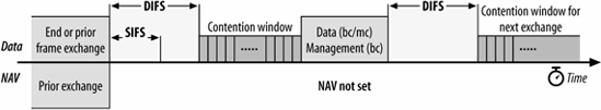
Depending on the environment, frames sent to group addresses may have lower service quality because the frames are not acknowledged. Some stations may therefore miss broadcast or multicast traffic, but there is no facility built into the MAC for retransmitting broadcast or multicast frames.
Unicast Frames
Frames that are destined for a single station are called directed data by the 802.11 standard. This book uses the more common term unicast. Unicast frames must be acknowledged to ensure reliability, which means that a variety of mechanisms can be used to improve efficiency. All the sequences in this section apply to any unicast frame and thus can apply to management frames and data frames. In practice, these operations are usually observed only with data frames.
Basic positive acknowledgment (final fragment)
Reliable transmission between two stations is based on simple positive acknowledgments. Unicast data frames must be acknowledged, or the frame is assumed to be lost. The most basic case is a single frame and its accompanying acknowledgment, as shown in Figure 3-15.
Figure 3-15. Basic positive acknowledgment of data

The frame uses the NAV to reserve the medium for the frame, its acknowledgment, and the intervening SIFS. By setting a long NAV, the sender locks the virtual carrier for the entire sequence, guaranteeing that the recipient of the frame can send the acknowledgment. Because the sequence concludes with the ACK, no further virtual carrier locking is necessary, and the NAV in the ACK is set to 0.
Fragmentation
Many higher-layer network protocols, including IP, incorporate fragmentation. The disadvantage of network-layer fragmentation is that reassembly is performed by the final destination; if any of the fragments are lost, the entire packet must be retransmitted. Link layers may incorporate fragmentation to boost speed over a single hop with a small MTU.[*] 802.11 can also use fragmentation to help avoid interference. Radio interference is often in the form of short, high-energy bursts and is frequently synchronized with the AC power line. Breaking a large frame into small frames allows a larger percentage of the frames to arrive undamaged. The basic fragmentation scheme is shown in Figure 3-16.
[*] This is the approach used by Multi-link PPP (RFC 1990).
The last two frames exchanged are the same as in the previous sequence, and the NAV is set identically. However, all frames prior to the penultimate frame use the NAV to lock the medium for the next frame. The first data frame sets the NAV for a long enough period to accommodate its ACK, the next fragment, and the acknowledgment following the next fragment. To indicate that it is a fragment, the MAC sets the More Fragments bit in the frame control field to 1. All nonfinal ACKs continue to extend the lock for the next data fragment and its ACK. Subsequent data frames then
Figure 3-16. Fragmentation
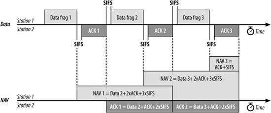
continue to lengthen the NAV to include successive acknowledgments until the final data frame, which sets the More Fragments bit to 0, and the final ACK, which sets the NAV to 0. No limit is placed on the number of fragments, but the total frame length must be shorter than any constraint placed on the exchange by the PHY.
Fragmentation is controlled by the fragmentation threshold parameter in the MAC. Most network card drivers allow you to configure this parameter. Any frames larger than the fragmentation threshold are fragmented in an implementation-dependent way. Network administrators can change the fragmentation threshold to tune network behavior. Higher fragmentation thresholds mean that frames are delivered with less overhead, but the cost to a lost or damaged frame is much higher because more data must be discarded and retransmitted. Low fragmentation thresholds have much higher overhead, but they offer increased robustness in the face of hostile conditions.
RTS/CTS
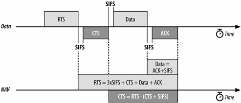
To guarantee reservation of the medium and uninterrupted data transmission, a station can use the RTS/CTS exchange. Figure 3-17 shows this process. The RTS/CTS exchange acts exactly like the initial exchange in the fragmentation case, except that the RTS frame does not carry data. The NAV in the RTS allows the CTS to complete, and the CTS is used to reserve access for the data frame.
RTS/CTS can be used for all frame exchanges, none of them, or something in between. Like fragmentation, RTS/CTS behavior is controlled by a threshold set in the driver software. Frames larger than the threshold are preceded by an RTS/CTS exchange to clear the medium, while smaller frames are simply transmitted.
Figure 3-17. RTS/CTS lockout
RTS/CTS with fragmentation
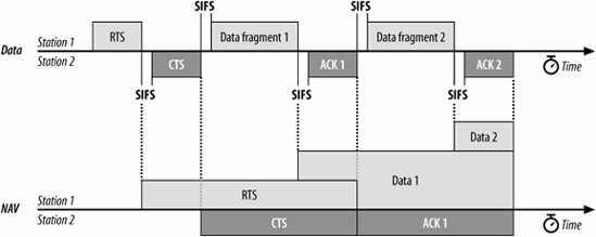
In practice, the RTS/CTS exchange is often combined with fragmentation (Figure 3-18). Fragmented frames are usually quite long and thus benefit from the use of the RTS/CTS procedure to ensure exclusive access to the medium, free from contention from hidden nodes. Some vendors set the default fragmentation threshold to be identical to the default RTS/CTS threshold.
Figure 3-18. RTS/CTS with fragmentation
Powersaving Sequences
The most power-hungry components in RF systems are the amplifiers used to boost a signal immediately prior to transmission and to boost the received signal to an intelligible level immediately after its reception. 802.11 stations can maximize battery life by shutting down the radio transceiver and sleeping periodically. During sleeping periods, access points buffer any unicast frames for sleeping stations. These frames are announced by subsequent Beacon frames. To retrieve buffered frames, newly awakened stations use PS-Poll frames.
An access point that receives a PS-Poll frame may respond with the requested data immediately, or at its leisure when circumstances permit. In some cases, the PS-Poll response is determined by the 802.11 chipset vendor in the AP. Some chipset vendors support both modes, while others support only one. 802.11 only requires that one method be supported; both approaches are equally standards-compliant.
Immediate response
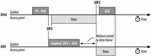
Access points can respond immediately to the PS-Poll. After a short interframe space, an access point may transmit the frame. Figure 3-19 shows an implied NAV as a result of the PS-Poll frame. The PS-Poll frame contains an Association ID in the Duration/ID field so that the access point can determine which frames were buffered for the mobile station. However, the MAC specification requires all stations receiving a PS-Poll to update the NAV with an implied value equal to a short interframe space and one ACK. Although the NAV is too short for the data frame, the access point acquires that the medium and all stations defer access for the entire data frame. At the conclusion of the data frame, the NAV is updated to reflect the value in the header of the data frame.
Figure 3-19. Immediate PS-Poll response
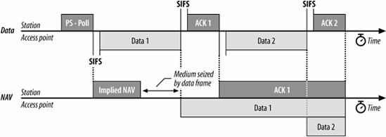
If the buffered frame is large, it may require fragmentation. Figure 3-20 illustrates an immediate PS-Poll response requiring fragmentation. Like all other stations, access points typically have a configurable fragmentation threshold.
Deferred response
Instead of an immediate response, access points can also respond with a simple acknowledgment. This is called a deferred response because the access point acknowledges the request for the buffered frame but does not act on it immediately. One of the advantages of using deferred response is that the software on the access point is somewhat easier to implement because the acknowledgment can be
Figure 3-20. Immediate PS-Poll response with fragmentation
transmitted immediately by the chipset firmware, and the buffered data may be queued for transmission normally.
A station requesting a frame with a PS-Poll must stay awake until it is delivered. Under contention-based service, however, the access point can deliver a frame at any point. A station cannot return to a low-power mode until it receives a Beacon frame in which its bit in the traffic indication map (TIM) is clear.
Figure 3-21 illustrates this process. In this figure, the station has recently changed from a low-power mode to an active mode, and it notes that the access point has buffered frames for it. It transmits a PS-Poll to the access point to retrieve the buffered frames. However, the access point may choose to defer its response by transmitting only an ACK. At this point, the access point has acknowledged the station's request for buffered frames and promised to deliver them at some point in the future. The station must wait in active mode, perhaps through several atomic frame exchanges, before the access point delivers the data. A buffered frame may be subject to fragmentation, although Figure 3-21 does not illustrate this case.
Figure 3-21. Deferred PS-Poll response example

After receiving a data frame, the station must remain awake until the next Beacon is transmitted. Beacon frames only note whether frames are buffered for a station and have no way of indicating the number of frames. Once the station receives a Beacon frame indicating that no more traffic is buffered, it can conclude that it has received the last buffered frame and return to a low-power mode.
Multirate Support
Network technologies that operate at a variety of different speeds must have a method of negotiating a mutually acceptable data rate. Speed negotiation is particularly that are available to stations. Stations may also change speed frequently in response to rapid changes in the radio environment. As the distance between stations varies, the speed will vary as well. Stations must adapt to the changing environment by altering transmission speed as necessary. As with many other protocol features, the 802.11 standards do not specify how a rate is selected. General rules are laid down by the standard, and vendors have a great deal of freedom in implementing the details. There are a few general rules that are required of all stations:
- Every station maintains a list of operational rates, which is the list of rates that are supported by both the station and the BSS serving it. (A BSS typically corresponds to an access point, but newer products may offer the ability to customize operational rates on a "virtual AP" basis.) No frames may be transmitted at a rate that is higher than any rate in the operational rate set.
- Every BSS must also maintain a basic rate set, which is a list of data rates that must be supported by every station joining the BSS. Any frame sent to a group receiver address must be transmitted at a basic rate, ensuring that all stations can demodulate it correctly.
- Control frames that start a frame exchange, such as RTS and CTS frames, must also be transmitted at one of the rates in the basic rate set. This rule ensures that a station which must transmit a CTS frame in response to an RTS frame can do so at the same rate.
Control frames may be used in a backwards-compatiblity mode called protection (see Chapter 14). Protection mode is intended to prevent interference between a station supporting only an older, slower radio modulation and a newer station that supports faster radio modulations. Protection frames must be transmitted using older modulations if there are stations incapable of using newer modulations in the area.
- Frames destined for a single station will have a unicast destination address in the Address 1 field of the frame. Unicast frames can be transmitted at any rate which is known to be supported by the destination. Selection of the data rate is not specified by any 802.11 standard.
Frames used in the contention-free period (see Chapter 9) may serve multiple purposes. If a frame includes an ACK, it is intended for the previous transmitter rather than the frame recipient. The transmitter must ensure that the frame is transmitted at a rate supported by both the receiver and the station the ACK is intended for.
- Response frames, such as acknowledgments or CTS frames, must be transmitted at a rate in the basic rate set, but no faster than the initial frame in the sequence was transmitted. Response frames must use the same modulation as the initial frame (DSSS, CCK, or OFDM).[*]
[*] This is not always strictly obeyed. One chipset vendor always tries to transmit ACK frames at 24 Mbps because it is usually the highest mandatory data rate.
Rate selection and fallback
Every 802.11 interface on the market supports some sort of rate fallback mechanism, which steps down the data rate in response to adverse network conditions. Rate selection behavior also determines when a card determines that it should upgrade its data rate due to improved link quality. Exactly how an 802.11 station determines it should go to a lower rate (or a higher rate) is not specified, so the implementation of rate selection is left to chipset vendors. Nearly every chipset has its own rate selection mechanism, and as a result, most 802.11 interfaces behave differently. Rate selection behavior is programmable, and is controlled by the code that runs the interface. It may be altered by driver version changes or firmware changes to an interface.
The most common algorithms used to determine when to change the data rate depend on some loose measurement of signal quality. Signal quality may be measured directly by the signal-to-noise ratio, or indirectly by observing how many frames require retransmission. Direct measurements of signal-to-noise ratios may be an instantaneous measurement of the last frame, or they may be averaged over some recent period or number of recently received frames. Some chipsets use a direct measurement of signal-to-noise ratio, but will convert it into a "signal quality" measurement first. As the signal quality drops, the chip reduces the data rate to compensate.[ ]
]
images/ent/U2020.GIF border=0>] The signal quality measurement is often used to make roaming decisions when stations move between APs, though no standard specifies how or even whether signal quality is an input to the algorithm.
Indirect measurements may monitor instantaneous or average frame loss, and compensate appropriately. A simple algorithm using indirect measurement is "if the frame is lost and the frame retry counter is exhausted, step down to the next data rate and try again; repeat until the frame is delivered or the slowest data rate is unable to successfully deliver." Chipsets that perform indirect signal quality measurements may make some modifications to avoid a time-consuming step down through all the rates supported by the PHY, especially since recent chipsets support a great number of rates, and the time to retry at the slower rates is extremely time-consuming.
Introduction to Wireless Networking
- Introduction to Wireless Networking
- Why Wireless?
- What Makes Wireless Networks Different
- A Network by Any Other Name...
Overview of 802.11 Networks
- Overview of 802.11 Networks
- IEEE 802 Network Technology Family Tree
- 11 Nomenclature and Design
- 11 Network Operations
- Mobility Support
11 MAC Fundamentals
- 11 MAC Fundamentals
- Challenges for the MAC
- MAC Access Modes and Timing
- Contention-Based Access Using the DCF
- Fragmentation and Reassembly
- Frame Format
- Encapsulation of Higher-Layer Protocols Within 802.11
- Contention-Based Data Service
- Frame Processing and Bridging
11 Framing in Detail
- 11 Framing in Detail
- Data Frames
- Control Frames
- Management Frames
- Frame Transmission and Association and Authentication States
Wired Equivalent Privacy (WEP)
- Wired Equivalent Privacy (WEP)
- Cryptographic Background to WEP
- WEP Cryptographic Operations
- Problems with WEP
- Dynamic WEP
User Authentication with 802.1X
- User Authentication with 802.1X
- The Extensible Authentication Protocol
- EAP Methods
- 1X: Network Port Authentication
- 1X on Wireless LANs
11i: Robust Security Networks, TKIP, and CCMP
- 11i: Robust Security Networks, TKIP, and CCMP
- The Temporal Key Integrity Protocol (TKIP)
- Counter Mode with CBC-MAC (CCMP)
- Robust Security Network (RSN) Operations
Management Operations
- Management Operations
- Management Architecture
- Scanning
- Authentication
- Preauthentication
- Association
- Power Conservation
- Timer Synchronization
- Spectrum Management
Contention-Free Service with the PCF
- Contention-Free Service with the PCF
- Contention-Free Access Using the PCF
- Detailed PCF Framing
- Power Management and the PCF
Physical Layer Overview
- Physical Layer Overview
- Physical-Layer Architecture
- The Radio Link
- RF Propagation with 802.11
- RF Engineering for 802.11
The Frequency-Hopping (FH) PHY
- The Frequency-Hopping (FH) PHY
- Frequency-Hopping Transmission
- Gaussian Frequency Shift Keying (GFSK)
- FH PHY Convergence Procedure (PLCP)
- Frequency-Hopping PMD Sublayer
- Characteristics of the FH PHY
The Direct Sequence PHYs: DSSS and HR/DSSS (802.11b)
- The Direct Sequence PHYs: DSSS and HR/DSSS (802.11b)
- Direct Sequence Transmission
- Differential Phase Shift Keying (DPSK)
- The Original Direct Sequence PHY
- Complementary Code Keying
- High Rate Direct Sequence PHY
11a and 802.11j: 5-GHz OFDM PHY
- 11a and 802.11j: 5-GHz OFDM PHY
- Orthogonal Frequency Division Multiplexing (OFDM)
- OFDM as Applied by 802.11a
- OFDM PLCP
- OFDM PMD
- Characteristics of the OFDM PHY
11g: The Extended-Rate PHY (ERP)
- 11g: The Extended-Rate PHY (ERP)
- 11g Components
- ERP Physical Layer Convergence (PLCP)
- ERP Physical Medium Dependent (PMD) Layer
A Peek Ahead at 802.11n: MIMO-OFDM
11 Hardware
- 11 Hardware
- General Structure of an 802.11 Interface
- Implementation-Specific Behavior
- Reading the Specification Sheet
Using 802.11 on Windows
11 on the Macintosh
Using 802.11 on Linux
- Using 802.11 on Linux
- PCMCIA Support on Linux
- Linux Wireless Extensions and Tools
- Agere (Lucent) Orinoco
- Atheros-Based cards and MADwifi
- 1X on Linux with xsupplicant
Using 802.11 Access Points
- Using 802.11 Access Points
- General Functions of an Access Point
- Power over Ethernet (PoE)
- Selecting Access Points
- Cisco 1200 Access Point
- Apple AirPort
Logical Wireless Network Architecture
- Logical Wireless Network Architecture
- Evaluating a Logical Architecture
- Topology Examples
- Choosing Your Logical Architecture
Security Architecture
- Security Architecture
- Security Definition and Analysis
- Authentication and Access Control
- Ensuring Secrecy Through Encryption
- Selecting Security Protocols
- Rogue Access Points
Site Planning and Project Management
- Site Planning and Project Management
- Project Planning and Requirements
- Network Requirements
- Physical Layer Selection and Design
- Planning Access-Point Placement
- Using Antennas to Tailor Coverage
11 Network Analysis
11 Performance Tuning
Conclusions and Predictions
EAN: 2147483647
Pages: 179
