QoS Tools
| Some of the various tools that implement QoS are described in this section and illustrated in Figure 6-2. Figure 6-2. QoS Tools Manage Network Traffic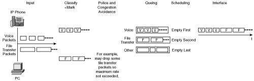 Many devices send data into a network. In the example shown in Figure 6-2, an IP phone produces packets that contain voice traffic, and a PC sends file transfer data. As the data enters the network, it is analyzed and classified according to how it should be dealt with in the network. After it is classified, the data is marked accordingly. Key Point Classification and marking form the basis for the rest of the QoS tools; it is here that business policies, priorities, and so forth are first implemented. The markings can then be used by other tools. For example, packets can be dropped by policing tools so that the maximum rate on an interface is not exceeded. Or packets can be dropped by congestion-avoidance tools to avoid anticipated interface congestion. Remaining packets are then queued, again according to their markings, and scheduled for output on the interface. Other tools, such as compression, can be implemented on the interface to reduce the bandwidth consumed by the traffic. The following sections explore these QoS tools:
Classification and MarkingBefore any traffic can be given priority over or treated differently than other traffic, it must first be identified. Key Point Classification is the process of analyzing packets and sorting them into different categories so that they can then be suitably marked; after they are marked, the packets can be treated appropriately. Marking is the process of putting an indication of the classification of the packet within the packet itself so that it can be used by other tools. The point within the network where markings are accepted is known as the trust boundary; any markings made by devices outside the trust boundary can be overwritten at the trust boundary. Establishing a trust boundary means that the classification and marking processes can be done once, at the boundary; the rest of the network then does not have to repeat the analysis. Ideally, the trust boundary is as close to end devices as possibleor even within the end devices. For example, a Cisco IP phone could be considered to be a trusted device because it marks voice traffic appropriately. However, a user's PC would not usually be trusted because users could change markings (which they might be tempted to do in an attempt to increase the priority of their traffic). ClassificationClassification can be done based on data at any of the OSI layers. For example, traffic can be differentiated based on the Layer 1 physical interface that it came in on or the Layer 2 source Media Access Control (MAC) address in the Ethernet frame. For Transmission Control Protocol/Internet Protocol (TCP/IP) traffic, differentiators include the source and destination IP addresses (Layer 3), the transport (Layer 4) protocolTCP or User Datagram Protocol (UDP), and the application port number (indicating Layer 7). Some applications require more analysis to correctly identify and classify them. For these cases, the Cisco Network-Based Application Recognition (NBAR) classification software feature, running within the IOS on Cisco routers, can be used. NBAR allows classification (and therefore marking) of a variety of applications, including web-based and other difficult-to-classify protocols that use dynamic TCP/UDP port assignments. For example, Hypertext Transfer Protocol (HTTP) traffic can be classified and marked by specifying uniform resource locators (URLs) so that a customer who is accessing an online ordering page could be given priority over someone accessing a general information page. Support for new protocols can be easily and quickly added through downloadable packet description language modules (PDLMs). Note You must enable Cisco Express Forwarding before you configure NBAR.[4] (See Chapter 2, "Switching Design," for information about Cisco Express Forwarding.) NBAR examines only the first packet of a flow; the rest of the packets belonging to the flow are switched by Cisco Express Forwarding. MarkingMarking can be done either in the Layer 2 frame or in the Layer 3 packet. For Ethernet frames, Layer 2 marking can be done using the following methods:[5]
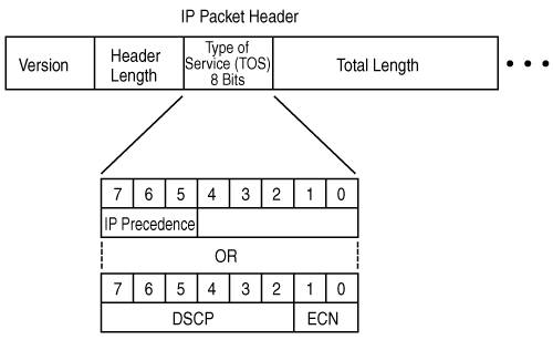
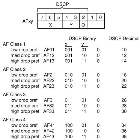
Because the CoS is represented by 3 bits, it can take on one of eight values, 0 through 7. Key Point Layer 2 markings are not useful as end-to-end QoS indicators because the media often changes throughout a network (for example, from Ethernet to a Frame Relay wide-area network [WAN]). Thus, Layer 3 markings are required to support end-to-end QoS. For IP version 4 (IPv4), Layer 3 marking can be done using the type of service (ToS) field in the packet header. Recall (from Appendix B) that this 8-bit field is the second byte in the IP packet header. (Figure B-11 illustrates all the fields in the IP packet header.) Originally, only the first 3 bits were used; these bits, called the IP Precedence bits, are illustrated in the middle of Figure 6-3. Packets with higher precedence values should get higher priority within the network. Because 3 bits again can only specify eight marking values, IP precedence does not allow a granular classification of traffic. Figure 6-3. The ToS Field in an IPv4 Header Supports IP Precedence or DSCP Thus, more bits are now used: The first 6 bits in the ToS field are now known as the DiffServ Code Point (DSCP) bits, and are illustrated in the lower portion of Figure 6-3. (The lower 2 bits in the ToS field are used for explicit congestion notification [ECN], which is described in the "Congestion Avoidance" section, later in this chapter.) With 6 bits, DSCP allows 64 marking values. DSCP values can be expressed numerically (with binary values from 000000 through 111111 or decimal values from 0 through 63) or by using Per-Hop Behavior (PHB) values; PHBs are just keywords that represent some numeric DSCP values. (The name per-hop behavior indicates that each device, or hop, should behave consistently when determining how to treat a packet.) Four PHB classes exist; they are described as follows:
Key Point We found that it is easy to get lost in the details of QoS markings, especially when the different PHBs, AF classes, and so forth are introduced. To hopefully avoid this confusion, remember these key points about QoS DSCP markings:
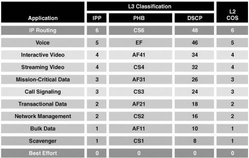
DSCP values can be represented numerically (in binary or decimal) or with keywords, known as PHBs. Each PHB (BE, CSx, EF, and AFxy) represents a specific numeric DSCP value and therefore a specific way that traffic should be handled. Cisco has created a QoS Baseline that provides recommendations to ensure that both its products, and the designs and deployments that use them, are consistent in terms of QoS. Although the QoS Baseline document itself is internal to Cisco, it includes an 11-class classification scheme that can be used for enterprises; this QoS Baseline suggestion for enterprise traffic classes is provided in Figure 6-5. This figure identifies the 11 types of traffic and the QoS marking that each type should be assigned. As described earlier, the QoS marking is either a Layer 2 CoS (specified within the 802.1q Tag field or ISL header) or a Layer 3 value marked in the IP packet header. The Layer 3 markings can either be done with a 3-bit IP precedence value (shown in the IPP column in Figure 6-5) or with a 6-bit DSCP value; both the numeric DSCP value and the PHB keyword representation of that value are shown in the figure. Figure 6-5. Cisco QoS Baseline Provides Guidelines for Classification and Marking[6] The classes of traffic in the QoS Baseline are defined as followed:
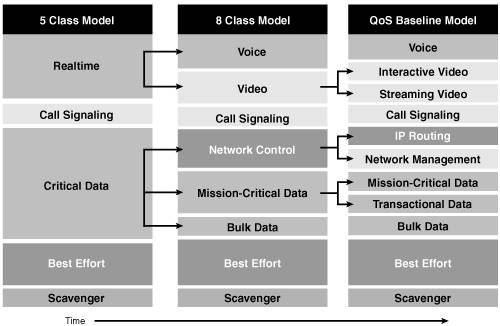
Key Point The QoS Baseline does not mandate that these 11 classes be used; rather this classification scheme is an example of well-designed traffic classes. Enterprises can have fewer classes, depending on their specific requirements, and can evolve to using more classes as they grow. For example, at one point, Cisco was using a 5-class model (the minimum recommended in a network with voice, video, and data) on its internal network.[7] Figure 6-6 illustrates an example strategy for expanding the number of classes over timefrom a 5-class, to an 8-class, and eventually to the 11-class modelas needs arise. Figure 6-6. The Number of Classes of Service Can Evolve as Requirements Change[8] After traffic has been classified and marked and sent on its way through the network, other devices can then read the markings and act accordingly. The following sections examine the QoS tools that these devices can use. Policing and ShapingPolicing and shaping tools identify traffic that violates some threshold or service-level agreement (SLA). The two tools differ in the way that they respond to this violation. Key Point Policing tools drop the excess traffic or modify its marking. Shaping tools buffer the extra data until it can be sent, thus delaying but not dropping it. The difference between these tools is illustrated in Figure 6-7. Figure 6-7. Policing Drops Excess Traffic While Shaping Delays It The diagram on the left in Figure 6-7 illustrates traffic that is being presented to an interface; note that some of the traffic exceeds the maximum rate allowed on the interface. If policing tools were configured on the interface, the excess traffic would simply be dropped, as indicated in the upper-right diagram. In contrast, the lower-right diagram shows that shaping tools would send all the data by delaying some of it until bandwidth is available. Policing ToolsThe Cisco IOS traffic policing feature allows control of the maximum rate of traffic sent or received on an interface. It is often configured on interfaces at the edge of a network to limit traffic into or out of the network. Traffic that does not exceed the specified rate parameters is sent, while traffic that exceeds the parameters is either dropped or is sent with a lower priority. Note Committed access rate (CAR) is an older IOS policing tool that can be configured to rate-limit (drop) certain traffic if it exceeds a specified speed. It can also be configured to set or change the markings within the packet header for traffic, depending on whether it meets or exceeds the acceptable rate. Shaping ToolsTraffic shaping allows you to control the traffic going out of an interface to match its flow to the speed of the destination interface or to ensure that the traffic conforms to particular policies. The IOS software supports the following QoS traffic-shaping features:
Note Priority and custom queuing are described in the "Congestion Management" section, later in this chapter. Congestion AvoidanceKey Point Congestion-avoidance techniques monitor network traffic loads so that congestion can be anticipated and then avoided, before it becomes problematic. If congestion-avoidance techniques are not used and interface queues get full, packets trying to enter the queue will be discarded, regardless of what traffic they hold. This is known as tail dropthe packets arriving after the tail of the queue are dropped. In contrast, congestion-avoidance techniques allow packets from streams identified as being eligible for early discard (those with lower priority) to be dropped when the queue is getting full. Congestion avoidance works well with TCP-based traffic; TCP has a built-in flow control mechanism so that when a source detects a dropped packet, the source slows its transmission. Weighted random early detection (WRED) is the Cisco implementation of the random early detection (RED) mechanism. RED randomly drops packets when the queue gets to a specified level (in other words, when it is nearing full). RED is designed to work with TCP traffic: When TCP packets are dropped, TCP's flow-control mechanism slows the transmission rate and then progressively begins to increase it again. RED therefore results in sources slowing down and hopefully avoiding congestion. WRED extends RED by using the IP precedence in the IP packet header to determine which traffic should be dropped; the drop-selection process is weighted by the IP precedence. Similarly, DSCP-based WRED uses the DSCP value in the IP packet header in the drop-selection process. WRED selectively discards lower-priority (and higher-drop preference for DSCP) traffic when the interface begins to get congested. Starting in IOS Release 12.2(8)T, Cisco has implemented an extension to WRED called explicit congestion notification (ECN), which is defined in RFC 3168, The Addition of Explicit Congestion Notification (ECN) to IP, and uses the lower 2 bits in the ToS byte (as shown earlier in Figure 6-3). Devices use these two ECN bits to communicate that they are experiencing congestion. When ECN is in use, it marks packets as experiencing congestion (rather than dropping them) if the senders are ECN-capable and the queue has not yet reached its maximum threshold. If the queue does reach the maximum, packets are dropped as they would be without ECN. Congestion ManagementWhile congestion avoidance manages the tail, or back, of queues, congestion management takes care of the front of queues. Key Point As the name implies, congestion management controls congestion after it has occurred. Thus, if no congestion exists, these tools are not triggered, and packets are sent out as soon as they arrive on the interface. Congestion management can be thought of as two separate processes: queuing, which separates traffic into various queues or buffers, and scheduling, which decides from which queue traffic is to be sent next. Queuing algorithms sort the traffic destined for an interface. Cisco IOS Software includes many queuing mechanisms. Priority queuing (PQ), custom queuing (CQ), and weighted fair queuing (WFQ) are the three oldest. IP Real-Time Transport Protocol (RTP) priority queuing was developed to provide priority for voice traffic, but it has been replaced by class-based weighted fair queuing (CBWFQ) and low latency queuing (LLQ). These queuing mechanisms are described as follows:
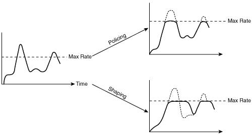
Note RTP is a protocol designed to be used for real-time traffic such as voice. RTP runs on top of UDP (to avoid the additional overhead and delay of TCP). RTP adds another header that includes some sequencing information and time-stamping information to ensure that the received data is processed in the correct order and that the variation in the delay is within acceptable limits.
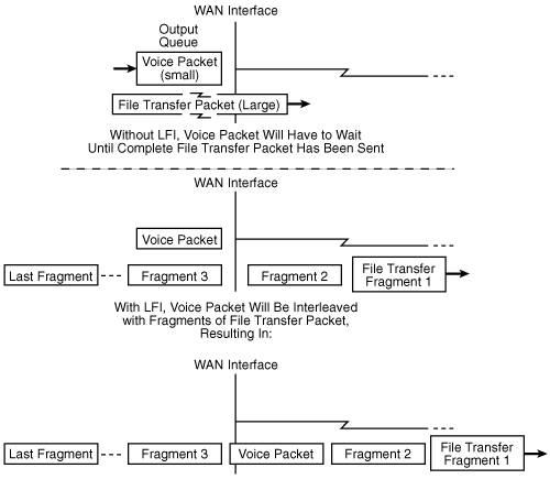
Key Point LLQ is the recommended mechanism for networks with voice traffic. Link-Specific ToolsKey Point Link-specific tools are those that are enabled on both ends of a point-to-point WAN connection to reduce the bandwidth required or delay experienced on that link. The QoS tools available include header compression (to reduce the bandwidth utilization) and link fragmentation and interleaving (LFI) (to reduce the delay encountered). Voice packets typically have a small payload (the voice data) relative to the packet headersthe RTP, UTP, and IP headers add up to 40 bytes. So, compressing the header of such packets can have a dramatic effect on the bandwidth they require. RTP header compression, called cRTP, compresses this 40-byte header to 2 or 4 bytes. Note Voice compression, which reduces the size of the voice payload while still maintaining the quality at an acceptable level, is described in Chapter 7. Even with queuing and compression in place, a delay-sensitive packet (such as a voice packet) could be ready to go out of a WAN interface just after a large packet (for example, part of a file transfer) has been sent on that interface. After forwarding of a packet out of an interface has begun, queuing has no effect and cannot recall the large packet. Therefore, a voice packet that gets stuck behind a large data packet on a WAN link can experience a relatively long delay and, as a result, the quality of the voice conversation can suffer. To counteract this, LFI can be configured on WAN links to fragment large packets (split them into smaller packets) and interleave those fragments with other packets waiting to go out on the interface. The smaller, delay-sensitive packets can travel with minimal delay. The fragments of the larger packets need to be reassembled at the receiving end, so the larger packets will experience some delay. However, because the applications sending these packets are not delay-sensitive, they should not be adversely affected by this delay. Figure 6-8 illustrates the LFI concept. Figure 6-8. LFI Ensures That Smaller Packets Do Not Get Stuck Behind Larger Packets Note Recall from Appendix B that the IPv4 packet header includes a 16-bit identification field consisting of 3 bits of flags and 13 bits of fragment offset. This field indicates whether the packet is a fragment and, if so, the offset of the fragment in the original packet. The receiving end can then reassemble the fragments to create the original packet. AutoQoSThe Cisco AutoQoS feature on routers and switches provides a simple, automatic way to enable QoS configurations in conformance with Cisco's best-practice recommendations. Only one command is required. The router or switch then creates configuration commands to perform such things as classifying and marking VoIP traffic and then applying an LLQ queuing strategy on WAN links for that traffic. The configuration created by AutoQoS becomes part of the normal configuration file and can, therefore, be edited if required. The first phase of AutoQoS, available in various versions of router IOS Release 12.3, only creates configurations related to VoIP traffic. Note The Cisco Feature Navigator tool, available at http://www.cisco.com/go/fn, allows you to quickly find the Cisco IOS and switch Catalyst Operating System (CatOS) Software release required for the features that you want to run on your network. For example, you can use this tool to determine the IOS release required to run AutoQoS on the routers in your network. The second phase of AutoQoS is called AutoQoS Enterprise and includes support for all types of data. It configures the router with commands to classify, mark, and handle packets in up to 10 of the 11 QoS Baseline traffic classes. The Mission-Critical traffic class is the only one not defined, because it is specific to each organization. As with the earlier release, the commands created by AutoQoS Enterprise can be edited if required. Note Further information on AutoQoS can be found at http://www.cisco.com/en/US/products/ps6656/products_ios_protocol_opt and at http://www.cisco.com/en/US/tech/tk543/tk759/tk879/tsd_technology_support_protocol_home.html. |
EAN: 2147483647
Pages: 156