Visually Developing Code
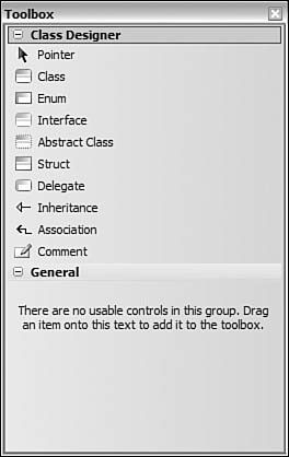
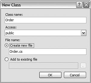
| As an architect, you get used to seeing things as diagrams. It is useful to think of your application as objects with specific semantics and relationships between one another. Most application architects and developers have been creating these types of diagrams for some time using the Unified Modeling Language (UML) or similar. These tools and modeling languages offer a great, abstract view of systems. However, they are difficult to keep in sync as your objects change. They also do not offer much assistance in terms of productivity or refactoring. Visual Studio 2005 provides the Class Designer as a new aid in this area. You can think of it as a modeling tool. However, its greatest strength lies in what it can do over and above representing your objects visually. It provides a real-time view of your code, along with the capability to edit this view. With the Class Designer, you can both model your application and visually develop code at the same time. Tip The class designer is a great way to come up to speed on existing code. With it, you can open an existing set of objects and quickly find out how they work with one another. Class DiagramThe class diagram is a modeling tool that is very important to the architect. However, unlike the models we have discussed previously, the class diagram is not specific to just the Team Architect version of Visual Studio. Instead, it is available to all roles in Team Systems. In fact, it is included in the Professional Edition. This is due to its nature as both a modeling tool and a development aid. With the class diagram, you can get actual, real-time synchronization with your code. Developers should think of it more like a visual code editor (and less like a diagram). If you make a change to code, that change is reflected in the diagram. When you change the diagram, your code changes, too. Creating a Class DiagramThere are a couple of ways to create a class diagram. The first is to add a class diagram to your project from the Add New Item dialog box. Here, you select a class diagram template (.cd) and add it to the project. You can then add items to this diagram from the Toolbox or from existing classes in the Solution Explorer. The second way to add a class diagram to a project is to choose View Class Diagram from the context menu for a given project. In this way, Visual Studio will generate a class diagram from an existing project. You still end up with a .cd file in your project, but you save yourself the time of dragging everything onto the diagram. Figure 21.29 shows an example of the Class Designer. We will cover each window shown in this designer. Figure 21.29. The Class Designer.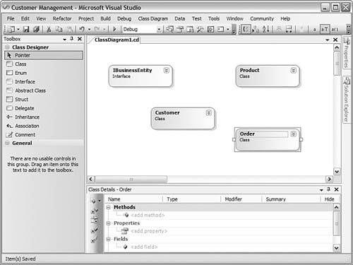 Displaying MembersYou use the arrow icon in the upper-right corner of each object to toggle whether to show or hide its members. This capability is helpful if you need to fit a lot of classes on a screen or if you are interested only in members of a particular class. You can also use the Class Designer toolbar to indicate how members are grouped for display and what additional information is shown. For example, you can sort members alphabetically, group them by their kind (property, method, and so on), or group by access (public, private, and so on). You can then indicate if you want to display just member names, their name and type, or the full signature. Adding ItemsYou add items to the Class Designer by using either the Toolbox or the Solution Explorer. The Toolbox is for new items. You use the Solution Explorer to add existing classes to the diagram. In both scenarios, you simply drag and drop the item to the Class Designer window. If the item already exists, then Visual Studio will build out the class details for you. In fact, if the class file contains more than one class, each class will be placed as an object on the diagram. To add new items to the diagram, you use the Class Designer Toolbox. Figure 21.30 shows an example of these tools. Notice that you can define all object-oriented concepts here, including classes, interfaces, inheritance, and so on. Figure 21.30. The Class Designer Toolbox. When you add a new item such as a class or struct to the designer, it will prompt you for its name and location. You can choose to generate a new file to house the item or place it in an existing file. Figure 21.31 shows the New Class dialog box. Here, you can give the class a name, set its access modifier, and indicate a filename. Figure 21.31. Adding a new class to the designer. Tip The Class Designer can automatically add related classes to the diagram. For example, suppose you add a class from the Solution Explorer. If you want to show classes that inherit from this class, you can right-click the class and choose Show Derived Classes. This will add to the model all classes that derive from the selected class. Defining Relationships Between ClassesOne of the biggest benefits of the class diagram is that it visually represents the relationships between classes. These relationships are much easier to see in a diagram than through code. The following relationships can be represented:
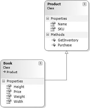
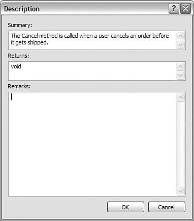
Let's look at implementing each of these relationships through an example. InheritanceFirst, let's look at inheritance with the class designer. Suppose you have a base class called Product. This class represents a generic product in your system. You then want to create a concrete Book class that inherits from Product. To do this with the Class Designer, you make sure both classes are on the screen. You then select the Inheritance tool from the Class Designer Toolbox. This tool has its own special icon that shows an arrow pointing upward. This visual cue indicates you want to draw the inheritance from the implementation class to the base class. Figure 21.32 shows this drawing in action. Figure 21.32. Defining inheritance.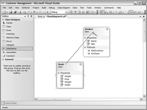 When the drawing is complete, the inheritance arrow should point toward the base class. Figure 21.33 shows an example. Also, notice the Book class now contains an icon indicating that it inherits Product. Figure 21.33. Inheritance defined. InterfaceThe next visual relationship we'll look at is an interface. For this example, suppose that all the business entities in your system implement a similar contract. This contract may define properties for ID and name. It may also define methods such as Get, Delete, and Save. To implement this interface, you again use the Inheritance tool from the Class Designer Toolbox. You drag it from the class doing the implementation toward the interface. Figure 21.34 shows the result of an implemented interface. Notice the lollipop icon above the Customer class; it denotes the interface implementation. Figure 21.34. Implementing an interface.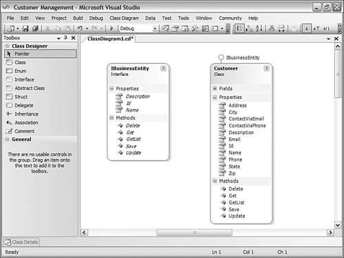 AssociationThe final relationship to look at is association. This relationship is typically a very loose one in the UML world. However, in the Class Designer, an association is very real. Typically, this means that two classes have an association through the use of one of the classes. This relationship is also optional in terms of viewing. It can exist, but you do not have to show it in the diagram. For example, suppose you have an Order object. This object might expose an OrderStatus property. Suppose it also has a property for accessing the Customer record associated with the order. These two properties are associations. You can leave them as properties, or you can choose to show them as associations. You can also draw these property associations on the diagram. To do so, you select the Association tool from the Toolbox. This tool has the same icon as Inheritance. You then draw the association from the class that contains the association to the class that is the object of the association. Figure 21.35 shows an example. Notice that the association property is displayed on the association arrow. This indicates that the class from where the association originates contains this property (it is shown only on this line, however). Figure 21.35. Creating an association.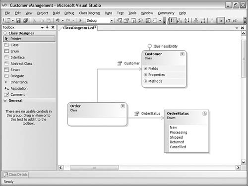 Defining Methods, Properties, Fields, and EventsThe most exciting part of the Class Designer is that it allows you to do more than define classes and relationships. You can actually stub out code and do refactoring (see Chapter 8, "Refactoring Code," for details). There are two ways to add code to your classes, structs, interfaces, and the like. The first is to type directly into the designer. For example, if you are in the Properties section of a class, you can right-click and choose to add a new property. This will place the property in your class and allow you to edit it in the diagram. This method works for other class members as well. It does have a couple of drawbacks, however. You can't, for instance, define a full method signature or indicate access levels. For that, you need the Class Details window. The Class Details window allows you to fully define methods, fields, properties, and events for a class. It also works with other constructs such as interfaces, delegates, and enums. To use this window, you right-click a class and choose Class Details from the context menu. Selecting this menu item brings up the Class Details editor for the selected class. Figure 21.36 shows an example. Figure 21.36. The Class Details window.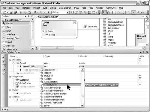 Notice that when working in the Class Details window, you still get IntelliSense. In this example, the Cancel method is being added to the Order class. You can indicate a return type for the method with the Type column. You can define the access modifier with the Modifier column. You can also set the parameters of the method. In this case, the method takes the parameter reasonCode. Finally, there are the Summary and Hide columns. The Hide column indicates whether you want to show an item on the diagram. This capability allows you to hide various members when printing or exporting as an image. The Summary column allows you to add your XML documentation to the class. Clicking the ellipsis button in this field will bring up the Description dialog box. Here, you can enter your XML summary information for the given member. Figure 21.37 shows an example. Figure 21.37. The Method Description dialog box. |
EAN: 2147483647
Pages: 195