Blocking Sensor Configuration
| [ LiB ] |
Now that we've gone through the fundamental concepts of blocking, we can go through the configuration tasks step-by-step.
The steps to configure blocking are as follows :
- Assign the block reaction to a signature. You can use either the IDS MC or the IDM to complete this task.
- Set the Sensor's global blocking properties. This step involves enabling blocking and defining blocking parameters such as block duration, maximum blocking entries, and whether to allow the Sensor's IP address to be blocked.
- Define the properties of the managed device. In this step, you define the blocking device's type, IP address, username, password, and communications method.
- Assign the managed interface's properties for IOS devices. This step is where you select the blocking interface or VLAN and assign pre-block and post-block ACLs or VACLs.
- (Optional) Assign never-block devices, which will never be added to the active ACL.
- (Optional) Define a master blocking sensor. This task involves designating the Sensor that will perform the blocking function for other blocking devices; it is covered in greater depth later in this chapter.
We now go through an example for each of the following device types: Cisco IOS Router, Cisco PIX Firewall, and Catalyst 6000 VACL. Because Steps 1 and 2 are the same for all devices, we focus on Steps 3 and 4 for each example.
Managed DeviceCisco IOS Router
The Cisco IOS device type can be any of the following:
-
Cisco IOS Router
-
Catalyst 5000 Series switch with an RSM or RSFC
-
Catalyst 6000 Series switch running native IOS with an MSFC
To configure blocking for this managed device, follow these steps:
- To define the properties for the managed device, navigate to Configuration, Settings on the IDS MC, and click on Blocking, Blocking Devices from the table of contents (TOC) on the left-side navigation bar.
- Click Add and enter values for the settings, as listed in Table 11.3.
Table 11.3. IDS MC Blocking Device Settings
Setting
Description
Device type
Drop-down menu where you can select the device type, such as IOS Router or PIX Firewall, for example.
IP address
IP address of the blocking device, in this case, the Cisco IOS Router.
NAT address
NAT IP address of the blocking device, in this case, a Cisco IOS Router.
Comment
Optional.
Username
Username that has permissions to log in and perform administration, configuration, or management functions (if the router is configured for user authentication).
Password
Console level password.
Enable password
Password that allows the user to perform administration, configuration, and management functions.
Secure communications
Drop-down menu where you can choose the method of communication between the Sensor and the Cisco IOS Router. The default value is None, which means that Telnet will be used. SSH or 3DES SSH are the other options.
- To configure blocking on the interface, on the Enter Blocking Devices page, click Edit Interfaces to display the Enter Blocking Devices Interfaces page.
- Click Add to set the Blocking Device Interface values.

If you choose to use SSH or 3DES SSH communications between the blocking device and the Cisco IOS Router, the router uses SSH password authentication rather than public key authentication. Recall also that your IOS device needs a license that supports either DES or 3DES for SSH communications to the blocking sensor.
- Manually configure the SSH public key with the ssh host-key ip_address command, where the IP address is the router's IP address. Once it has the correct router IP address, the sensor then automatically retrieves the SSH parameters from the router.
- To configure the router as an SSH server, first enable the SSH server and generate the server public and private authentication keys using the IOS crypto key generate rsa command. The following example shows a partial configuration, used to configure local database authentication:
[View full width]! username kristina password 0 secret # Sensor username account for SSH login ! aaa new-model aaa authentication login ssh local enable # Define aaa profile "ssh" for local user
 database authentication; enable password as backup ! ip domain- name kristina.net # Establish identity ip ssh time-out 90 # Optional (Default = 80) ip ssh authentication-retries 2 # Optional (Default = 3) ! line vty 0 4 login authentication ssh # Authenticate vty lines using aaa profile "ssh" transport input ssh # Enable the ssh transport on the vty line !
- Verify your settings with the IOS commands show users and show ssh , which show the established SSH connection and encryption level, respectively.
- On the Sensor from the IDS MC Blocking Device Interface page, shown in Figure 11.4, enter the values for the Blocking Device Interface settings. These settings are listed and described in Table 11.4.
Figure 11.4. The Blocking Device Interface page.
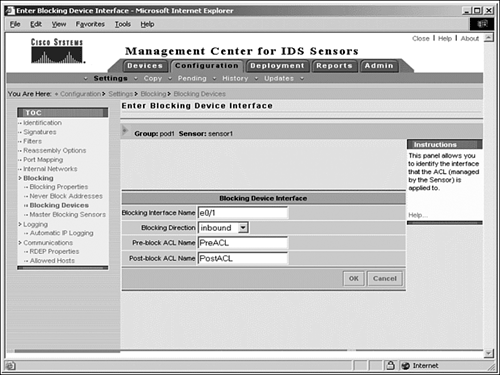
Table 11.4. IDS MC Blocking Device Interface Settings
Setting
Description
Blocking interface name
Allows you to name the blocking managed interface
Blocking direction
Drop-down menu allowing you to specify whether the ACL is inbound or outbound
Pre-block ACL name
Name of the ACL that has the entries to include above the blocking ACEs
Post-block ACL name
Name of the ACL that has the entries to include below the blocking ACEs
- Click OK to display the Enter Blocking Device Interface page. Click OK again on this page and the Enter Blocking Device to save and apply the settings to your Sensor.
Managed DeviceCisco PIX Firewall
For PIX Firewalls running version 6.0 and later, you perform blocking using the shun command rather than ACLs or interfaces. Blocking with the shun command is limited to hosts and connections rather than subnets or entire networks.
To add a PIX Firewall as a managed device, complete the following steps:
- From the IDS MC, navigate to the Configuration, Settings page and click on Blocking, Blocking Devices from the TOC on the left.
- Click Add to display the Enter Blocking Devices page, and enter the values for the Blocking Device Settings, as shown in Table 11.5.
Table 11.5. IDS MC Blocking Device Settings
Setting
Description
Device type
Drop-down menu where you can select from the device type, such as IOS Router or PIX Firewall, for example.
IP address
IP address of the blocking device, in this case, the PIX Firewall.
NAT address
NAT IP address of the blocking device, in this case, a PIX Firewall.
Comment
Optional.
Username
Username that has permissions to log in and perform administration, configuration, or management functions (if the PIX Firewall is configured for user authentication).
Password
Console level password.
Enable password
Password that allows the user to perform administration, configuration, and management functions.
Secure communications
Drop-down menu where you can choose the method of communication between the Sensor and the PIX Firewall. The default value is None, which means that Telnet will be used. SSH or 3DES SSH are the other options.
If you choose to use SSH or 3DES SSH communications between the blocking device and the Cisco PIX Firewall, the firewall uses SSH password authentication rather than public key authentication. Recall again that your PIX device needs a license that supports either DES or 3DES for SSH communications to the blocking sensor.
- Manually configure the SSH public key with the ssh host-key ip_address command, where the IP address is the firewall's IP address. Once it has the correct firewall IP address, the sensor then automatically retrieves the SSH parameters from the firewall.
- Configure the PIX Firewall as an SSH server. The following example shows a partial configuration for a PIX Firewall that supports SSH authentication from the Sensor using local password authentication rather than the authentication, authorization, and accounting (AAA) example we used earlier:
[View full width]passwd d4n1e1 # Define the SSH local password hostname kmmpix # Establish identity for key generation domain-name kristina.net # Establish identity for key generation ssh 172.16.1.25 255.255.255.255 inside # Allow SSH communication only from the
host 172.16.1.25 on the inside interface ssh timeout 60 # Optional
- After defining the hostname and domain name for the PIX, use the PIX ca generate rsa key command to generate the server public and private keys for SSH authentication; use the ca save all command to save the Rivest, Shamir, Adleman (RSA) key pair to flash.
- Verify your settings with the show ssh sessions command to verify that the firewall and the Sensor have established an SSH connection and to view the encryption level.
| | On the PIX Firewall, if you use local authentication rather than AAA authentication, the username is always pix . |
Managed DeviceCisco Catalyst 6000 VACL
For a Catalyst 6000 running the Catalyst OS, you use VACLs rather than ACLs to configure blocking. Also, Catalyst 6000 VACLs do not support direction-based ACLs, so you don't need to specify a direction for the interface.
To add a Catalyst 6000 as a managed device, complete the following steps:
- From the IDS MC, navigate to the Configuration, Settings page and click on Blocking, Blocking Devices from the TOC on the left.
- Click Add to display the Enter Blocking Devices page, and enter the values for the Blocking Device Settings, as described in Table 11.6.
Table 11.6. IDS MC Blocking Device Interface Settings
Setting
Description
Device type
Drop-down menu where you can select from the device type, such as PIX Firewall or Catalyst 6000, for example.
IP address
IP address of the blocking device, in this case, the Catalyst 6000.
NAT address
NAT IP address of the blocking device, in this case, a Catalyst 6000.
Comment
Optional.
Username
Username that has permissions to log in and perform administration, configuration, or management functions (if the router is configured for user authentication).
Password
Console level password.
Enable password
Password that allows the user to perform administration, configuration, and management functions.
Secure communications
Drop-down menu where you can choose the method of communication between the Sensor and the Catalyst 6000. The default value is None, which means that Telnet will be used. SSH or 3DES SSH are the other options.
Recall that if the blocking device is a Catalyst 5000 RSM or RSFC, or a Catalyst 6000 with an MSFC running native IOS, then you configure blocking using the Cisco IOS Router configuration steps, as covered in the earlier section.
- Enter the values for the IDS MC Blocking Device Interface settings, as described in Table 11.7.
Table 11.7. IDS MC Blocking Device Interface Settings
Setting
Description
VLAN number
Number of the VLAN that will be used to initiate blocking
Pre-block ACL name
Name of the ACL that has the entries to include above the blocking ACEs
Post-block ACL name
Name of the ACL that has the entries to include below the blocking ACEs
- Click OK to display the Enter Blocking Interface page; click OK on the Enter Blocking Interface page and the subsequent Blocking Device page to save and apply your settings.
Never-Block Addresses
A never-block ACL contains the ACEs for the hosts or subnets that should never be blocked. It consists of a permit statement for each host or subnet at the beginning of the active ACL. The address entries in a never-block ACL can include hosts and servers that provide critical network services which, if blocked, would have a severe impact on business operations. They can also include devices whose normal behavior emulates that of an attack and would otherwise cause a large number of false positives. If you choose to specify never-block addresses, make sure that you take additional measures to ensure that these addresses cannot be compromised to launch further attacks.
As you saw with the Sensor, if you configure them to never block, these addresses are added as permit statements in the active ACL.
To add never-block addresses, complete the following steps:
- Navigate to the Configuration, Settings page and click on Blocking, Never Block Addresses from the TOC on the left.
- Click Add to display the Enter Network page.
- Enter the IP address of the host or network that you want to never be blocked.
- Enter the network mask in the Network Mask field and an optional comment in the Comment field. Click OK to save and apply your changes.
| [ LiB ] |