WPANs
WMANs, WLANs, and WPANs
Today's consumer appetite for wireless broadband and the high-bandwidth applications it supportssuch as photos, games, and videois enormous. However, the demands placed on a network to support these advanced applications create a technology dilemma for today's network equipment makers and wireless carriers. Among the issues is the question of how an already scarce spectrum can carry more bandwidth-intensive data and multimedia services and do so more economically and reliably. This chapter explores the developments, standards, and deployments in wireless metropolitan area networks (WMANs), wireless local area networks (WLANs), and wireless personal area networks (WPANs), which are all critical to enabling the wireless society the public is hungry for.
The next wave of personal productivity is all about mobilitybeing able to get access anywhere, anytimewhich is driving the demand for wireless access. People use their laptops more when they have wireless access and are therefore more productive. It is easy to see why many industries will turn to wireless to boost productivity, and during the next 5 to 10 years, wireless MANs, LANs, and PANs will be instrumental to bringing wireless broadband not just to offices and homes but to users, wherever they may be.
Although in the past there were clear demarcations between what comprised a MAN, LAN, or PAN domain, today those boundaries are often blurred, particularly as the technologies complement one another. Therefore, the merging and working together of MANs, LANs, and PANs to create a seamless, always-on, and always-available network environment is a natural outcome. MANs, LANs, and PANs are each distinguishable today by definitions and parameters set in the standards, but as technologies advance, expand, and merge, we can expect that the application and implementation will define the domain rather than traditional physical parameters, such as range of coverage. In addition, domains will continue to evolve so that in the near future, we'll be discussing body area networks (BANs), fabric area networks (FANs), and, dare I say, even implant area networks. (Implant area networks do not exist as of yet, but given the rapid and vast progress in implants, from medical to financial to security to identity applications, it is only natural that we envision a network, perhaps relying on our own human physiology, that serves the communications needs of the multitude of life-enhancing implants lodged in the twenty-first-century definition of an intelligent being.)
As shown in Table 15.1, the IEEE (www.ieee.org) and ETSI (www.etsi.org) have both established hierarchies of wireless standards designed to complement each other. (As described later in this chapter, other areas of the world follow different standards; some follow the U.S. standards, some follow the European standards, and some create proprietary standards on top of those, such as WiBro in Korea, iBurst in Australia, and TD-SCDMA in China.) Each standard is designed for a distinct market and for different usage models. These standards and others used in WMANs, WLANs, and WPANs are discussed in this chapter.
|
Network Type |
United States |
Europe |
|---|---|---|
|
WAN |
IEEE 802.20x (Mobile-Fi) |
EDGE (GSM), 3GPP (UMTS) |
|
MAN |
IEEE 802.16x (WiMax) |
ETSI HiperMAN, HiperAccess |
|
LAN |
IEEE 802.11x (Wi-Fi) |
ETSI HiperLAN |
|
PAN |
IEEE 802.15x (Bluetooth) |
ETSI HiperLAN |
WLANsThe world of WLANs is truly an exciting area, with major activity worldwide, challenging traditional service providers and business models. Initially, WLANs were meant to be an augmentation, not a replacement, of wired LANs and premises telephone systems. WLANs were deployed in enterprise or corporate locations where there might be a number of factors that limited or prevented wired systems from being installed. Today, we see much greater utility for WLANs, as evidenced by the emergence of thousands of hotspots around the world. In some cases, it is cheaper to deploy wireless in an office than to replace a crumbling old token-ring cable plant with shiny new Ethernet. In general, WLANs operate over short ranges, anywhere from 10 to 500 feet (3 to 150 m), so their coverage areas are microcells or picocells. Like many other telecom technologies, WLANs have gone through various generations, and the data rates supported reflect that evolution. The early products were quite limited, operating at only 1Mbps to 11Mbps, with the actual throughput being 50% or less of the maximum rate quoted. But the newer standards support data rates of up to 54Mbps, with the actual throughput being up to 32Mbps, and emerging standards promise 100Mbps to 200Mbps. From the standpoint of an enterprise user, the primary applications for early WLANs were to reduce the costs associated with moves, adds, and changes; simplify installation procedures; and enable mobility within the building or campus environment. In the realm of the public domain today, the primary application for WANs is simply mobilityto accommodate the rapidly growing number of road warriors as well as consumers who want to communicate, work, and play anytime, anywhere. WLANs typically operate on unlicensed frequency bands, either the 2.4GHz or 5GHz bands. They do not require line-of-sight conditions, which is a very desirable feature. The key element of a WLAN is a wireless access point (WAP), or base station. WAPs are connected to an Ethernet hub or server and transmit a radio frequency over an area of several hundred feet, which can penetrate walls and other nonmetal barriers. The total coverage area can be extended by connecting numerous WAPs. Roaming users are accommodated by handoffs between the WAPs. Figure 15.4 shows an example of a WLAN. Figure 15.4. An example of a WLAN 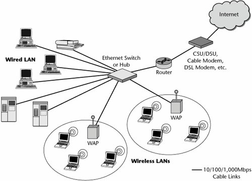
The applications for WLANs include low-cost installation, mobility, and support for temporary arrangements. For example, retailers often reconfigure their displays within a store and reassign where the cash registers need to be, and the only rapid deployment solution is wireless. As another example, if a natural disaster such as a flood or an earthquake disables the existing wireline facilities, the only quick road to disaster recovery is wireless. Other applications include scenarios where there may be environmental hazards such as asbestos in the building, or where there is a desire or requirement to preserve a historic building containing marble walls or oak paneling where it would be a shame to destroy such richness with intrusive installation procedures. In each of these cases, wireless presents an elegant, fast, and low-cost solution to getting service in and running. The following sections describe a number of facets of WLANs:
Wi-Fi The concept of readily available WLANs is being globally embraced. Many WLANs are being set up by grassroots groups that want to get on the Internet by sharing local connections. This opportunity is putting the grassroots networks on a collision course with cable companies and telecom carriers because it provides an opportunity for even an individual citizen to become a "telecom provider" to his or her neighbors. These new community wireless networks are based on Wi-Fi technology. Wi-Fi allows users to plug a single high-speed Internet connection such as a cable modem into a US$100 to US$175 WAP and share it with scores of people in a building, park, or small neighborhood. Anyone can snap a US$50 antenna into a laptop and tap into many of these unsecured mini-networks for free, without permission. Those with clever entrepreneurial tendencies might charge their neighbors anywhere from US$5 to US$75 per month and become the neighborhood high-speed data access provider, and it's all legal (at least at the moment and in the United States). Wi-Fi is popping up at thousands of hotspots, in locations including hotels, airports, shopping centers, restaurants/cafes, and educational environments; basically, wherever people congregate, there is an application for a hotspot. Hotspots are much less expensive to build than 3G systems, and they offer similar data capabilities, although voice service is not yet a reliable application on WLANs. Therefore, WLANs and cellular are uniting to provide road warriors with a complete toolkit. Wi-Fi is a trade term promulgated by the Wi-Fi Alliance (www.wirelessethernet.org). Products that the Wi-Fi Alliance certifies are interoperable with each other, even if they are from different manufacturers. A user with a Wi-Fi product can use any brand of WAP with any other brand of client hardware built to the Wi-Fi standard. Even though Wi-Fi is extremely cost-effective to deploy and is extremely popular today, some issues need to be recognized:
WLANs are being set up by all sorts of groups, from grassroots organizations to powerful retailers, hospitality organizations, and transportation enterprisesall focused on the benefits of allowing their constituents the opportunity to get on the Internet by sharing local connections. What is the motivation for them to implement and market WLAN services? For small entrepreneurs and technology lovers, doing so supports the dream of doing something positive in the development and deployment of communications technology required by the average citizen. For large business enterprises, doing so creates an opportunity to grow customer loyalty, an all-important objective today, and also provides a venue for generating new revenuesnot just from the subscription to the network service or usage fees, but also because clients are likely to spend more time in the establishment working on e-mails and Web surfing and thus likely to buy more of the core product, whether it is another cup of coffee or another order of fries. IEEE 802.11x Standards WLANs encompass a number of different standards, but the most important are those from the IEEE 802.11 Working Group. The 802.11 Working Group comprises many individual task groups charged with developing various aspects of WLAN standards, referenced as 802.11x, with x denoting the specific task group and its objective. (The x does not, in this case, indicate the name of a specific protocol.) This section focuses primarily on the standards that are essential to your knowledge of WLANs, but you should have a general feel for what each specification addresses, so Table 15.5 gives a quick summary of the whole 802.11 family.
The 802.11 specifications were initially introduced in 1997 for operation in the unlicensed 2.4GHz band, and they included two spread spectrum methods for transmission: 1Mbps Frequency Hopping Spread Spectrum (FHSS) and 1Mbps and 2Mbps Direct Sequence Spread Spectrum (DSSS). An infrared method was also specified. Ultimately, the Wi-Fi Alliance dropped both FHSS and infrared, but the 1Mbps DSSS method is still used by WAPs to advertise themselves (in a process known as beaconing). Now 802.11 is sometimes called 802.11 legacy.
Commonly Used 802.11 Standards: 802.11b, 802.11a, and 802.11g The standards 802.11b, 802.11a, and 802.11g are the most commonly used today; their specifications are shown in Table 15.6.
IEEE 802.11b, published in 1999, was the first widely accepted wireless networking standard. The main objective of this standard was to boost the original 802.11 data rate (1Mbps to 2Mbps) to 11Mbps. However, due to the CSMA/CA access technique and distance variables, the actual throughput is likely to be more on the order of 5Mbps or less. IEEE 802.11b operates in the unlicensed 2.4GHz band, over a range of approximately 300 feet (100 m). It relies on DSSS transmission technology. This standard makes use of a variety of different phase-shift keying (PSK) modulation schemes, depending on the data rate required. At the basic rate of 1Mbps, it uses DBPSK (Differential Binary PSK). To provide the extended rate of 2Mbps, it uses DQPSK (Differential Quadrature PSK). In reaching 5.5Mbps and the full rate of 11Mbps, 802.11b uses QPSK, coupled with an error control technique called Complementary Code Keying (CCK). IEEE 802.11a, also published in 1999, makes use of OFDM transmission, increasing the speeds to a theoretical rate of 54Mbps, but with a real throughput experience of 27Mbps or less. This standard operates in the 5GHz range over a smaller coverage range of 150 feet (50 m). (Remember that the higher the frequency, the faster the signal loses power, which means the coverage area must be smaller.) IEEE 802.11a is not backward compatible with 802.11b. Published in 2003, IEEE 802.11g uses OFDM and operates in the 2.4GHz band, with a range of up to 300 feet (100 m). Because 802.11g transmits in the same band as 802.11b, the standards are compatible. However, if 802.11b and 802.11g devices are communicating with each other, they perform at the lowest common denominator, so they operate at the slower 802.11b speed. IEEE 802.11g supports 54Mbps in theory, but it offers an actual throughput of 27Mbps under ideal conditions and less when the distance between the transmitter and receiver is longer. In addition, in networks where the WAPs support a mix of 802.11b and 802.11g, the throughput drops to 18Mbps, and when multiple clients are transmitting, the throughput is further reduced to approximately 6Mbps to 9Mbps.
Standards 802.11a and 802.11g have eight data rates: 6Mbps, 9Mbps, 12Mbps, 18Mbps, 24Mbps, 36Mbps, 48Mbps, and 54Mbps. The 6Mbps and 9Mbps modes use the BPSK modulation technique. The 12Mbps and 18Mbps modes use QPSK. The 24Mbps and 36Mbps modes use 16-QAM, and 48Mbps and 54Mbps use 64-QAM. The 802.11 systems divide the spectrum into channels, enabling multiple WAPs to operate close to each other without interference because each one can be set to a different channel. However, 802.11b and 802.11g use overlapping channels. This means that in the United States and Asia, only 3 channels can be used, effectively allowing only 3 WAPs to operate without interference. In Europe, 4 channels are available. With 802.11a, the channels do not overlap, so in the United States, 12 channels are available, allowing 12 WAPs to operate in the same vicinity. In Asia, 4 channels can be used, and in Europe, 15 channels are available. Two modes of operation are specified in 802.11: infrastructure and ad hoc. In the infrastructure mode, the laptops or other wireless devices transmit to a base station, the WAP, which then connects to a wired LAN. Each WAP with its wireless devices is known as a basic service set (BSS). When there are two or more BSSs in the same subnet, it is called an extended service set (ESS). In the ad hoc mode, also called peer-to-peer mode, laptops and other wireless devices communicate directly with one another in a peer-to-peer fashion; no WAP is used. This is called an independent BSS (IBSS). Emerging 802.11 Standards: 802.11e, 802.11i, and 802.11n Three emerging standards802.11e, 802.11i, and 802.11nshow promise in terms of addressing the deficiencies of current WLANs. The objective of IEEE 802.11e is to provide for QoS extensions to the 802.11 protocol in support of LAN applications that have QoS requirements. The 802.11e standard allows for real-time audio and video streams to be given a higher priority over regular data. Examples of applications include transport of audio and video over 802.11 wireless networks, videoconferencing, media stream distribution, enhanced security applications, and mobile and nomadic access applications. The operation of the 802.11e standard is discussed further later in this chapter, in the section "VoWLAN." IEEE 802.11i, ratified in 2004, is a critical standard because it specifies enhanced security mechanisms for Wi-Fi. The initial security mechanism for 802.11 networks, called Wired Equivalent Privacy (WEP), was shown to have severe security weaknessesenough to discourage many people from deploying wireless. In response, the Wi-Fi Alliance introduced Wi-Fi Protected Access (WPA), a subset of 802.11i, as an intermediate solution to WEP insecurities. The Wi-Fi Alliance refers to its approved, interoperable implementation of the full 802.11i as WPA2. The next section, "WLAN Security," examines the specifics of 802.11i and WPA2. Perhaps the most eagerly awaited 802.11 standard is IEEE 802.11n, which is expected by 2007. A major enhancement to the 802.11 standard, its objective is to increase transmission speeds to 100Mbps and beyond. In fact, the real data throughput is estimated to reach a theoretical 54Mbps. IEEE 802.11n makes use of multiple-input multiple-output (MIMO) technology, which significantly improves performance and boosts the data rate. At the moment, two competing technologies are both MIMO based:
In order to speed the 802.11n development process and promote a technology specification for interoperability of next-generation WLAN products, the Enhanced Wireless Consortium (EWC; www.enhancedwirelessconsortium.org) was formed. The 802.11n Working Group approved the EWC's specification as the draft approval of 802.11n in January 2006. WLAN Security The flaws in Wi-Fi security have given rise to war driversindividuals who drive through an area, scan for wireless networks (using programs such as NetStumbler), and publish their findings on the Web. The term is derived from war dialing, a method hackers use to locate nonsecure computers by dialing through phone numbers. The original 802.11b security mechanism is static WEP. Static WEP uses a 40- or 104-bit encryption key, which is manually entered and applied and then is not typically changed. WEP has been shown to be easily compromised and is generally not considered secure. Programs such as AirSnort can obtain encryption keys. Most wireless networks fail to make use of even WEP. The good news is that WEP is not the only available WLAN security mechanism. The continuum of IEEE wireless security standards also includes static WEP with initialization vector (IV), dynamic WEP, WPA, and WPA2. Static WEP with IV Static WEP is today often enhanced with IV, a 24-bit "starting point" value appended to basic WEP. Adding 24 bits to a WEP key results in 64- or 128-bit composite key values. Static WEP with IV is supported by all current VoWLAN handsets. Dynamic WEP Dynamic WEP, which has generally replaced static WEP, is an incremental security improvement over basic static WEP. It involves mutual authentication using 802.1X and generation of unique encryption keys for each associated client. WPA WPA is the current state-of-the-art in standards-based WLAN security. It is an enhanced wireless security environment that replaces dynamic WEP. WPA includes three main elements:
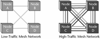
Like dynamic WEP, WPA generates unique keys for each associated client computer and takes care of distributing them securely. WPA2 WPA2 is embodied in the IEEE 802.11i specification, and it is the most long-term solution of the current WLAN security standards. It is the latest-generation wireless security environment, meant to enhance and supplant WPA. WPA2 differs from WPA in that it uses AES rather than RC4 and doesn't need a MIC because the same AES key is used for both encryption and integrity. WPA2 still relies on 802.1X for authentication. AES supports encryption keys of 128, 196, and 256 bits. All Wi-Fi hardware manufactured after August 2004 includes support for WPA2. VoWLAN Two hot networking technologies, VoIP and WLANs, have come together to provide a local voice solution, VoWLAN, that marries the convenience of mobility with the cost-effectiveness of an IP PBX. VoWLAN Support Concerns There are three primary concerns regarding support of VoWLAN: security, handoff capability, and capacity and QoS. The following sections discuss these concerns. VoWLAN Security The major struggle with WLANs has been to start with a technology created for residential and consumer applications and to strengthen it to the point where it can support enterprise requirements. The most critical issue has been the ongoing security problems created by 802.11's weak WEP encryption and authentication systems. As discussed in the preceding sections, however, there is plenty of good news regarding recent developments in WLAN security. Most security concerns should be addressed by the WPA standard, along with IEEE's 802.1X authentication framework, and ultimately the 802.11i encryption standard. VoWLAN Handoffs Another potential problem with VoWLAN has to do with handoffs. Voice users' requirements for mobility will be greater than those of data users, so voice handoffs are more likely. A call handoff must occur quickly, and the authentication and encryption must remain intact. Handoffs can be several seconds long. The problem is that most traditional data-oriented authentication systems require that the device be reauthenticated when moving to a new WAP. The IEEE is looking for a 20-millisecond handoff capability for voice calls. Vendors today have introduced proprietary solutions to address the handoff concern, but eventually a standards-based solution will emerge. Meanwhile, a user must weigh the functionality that can be delivered immediately against the potential risk of being locked in by a vendor's proprietary solution. The VoWLAN solution is typically implemented as an adjunct to an existing circuit-switched or IP-based PBX. In either case, there are three main elements in a VoWLAN solution: VoWLAN telephone sets, WLANs, and gateways. VoWLAN telephone sets include digital telephones and other voice-capable devices that support an 802.11 WLAN interface. One issue regarding VoWLAN phones is the codec or voice-encoding rate. The main choices include G.711, the public network standard that requires 64Kbps per voice channel, and G.729a, a more bandwidth-efficient low-bit-rate option, which calls for 8Kbps per voice channel. The main tradeoff between the two standards is a 15- to 30-millisecond increase in delay due to compression when using G.729a. VoWLAN Capacity and QoS Capacity and QoS are discussed together here because the issues of providing adequate capacity while minimizing delay and jitter can be addressed by increasing the overall network capacity by offering higher bandwidth or by ensuring that voice packets are recognized and given priority over data packetsin other words, through managed bandwidth. Remember that WLANs were designed first and foremost for the requirements of data devices. They incorporate no inherent mechanisms for controlling latency or jitter. WLANs are half-duplex (only one part can send at a time), they share media (all users in an area share one radio channel), and the transmission rate depends on the distance from the end station to the WAP and on the effects of any impairments in the environment. The CSMA/CA process used in the 802.11 MAC protocol uses a system of backoff timers to help avoid collisions. All successful transmissions must be acknowledged, and if no acknowledgment is received, the transmitter sets a backoff counter with a random value. That backoff value is increased with every unsuccessful attempt. Because of these processes, the effective throughput of a WLAN is only some 50% to 55% of the raw transmission rate. These factorschannel contention, waiting intervals, acknowledgments, and retransmissionsmake it virtually impossible to provide a service that has consistent delay. To work around this, as with other packet voice systems, a time stamp is placed in the Real-Time Transport Protocol (RTP) header of each voice packet, and a buffer at the receiving end is used to mask the jitter effect. The long-term solution to the problem of capacity and QoS in VoWLANs is an enhanced MAC-layer protocol called Hybrid Coordination Function (HCF) that is developed in the IEEE 802.11e specification. The 802.11e HCF protocol is a very important development in VoWLAN systems. In order to improve service for voice, the standard includes two operating modes, either of which can be used: Enhanced Digital Control Access (EDCA) and Polled Access. EDCA EDCA, which is mandatory, is an enhanced version of the Distributed Control Function (DCF) defined in the original 802.11 MAC protocol. EDCA defines eight levels of access priority to the shared wireless channel. EDCA access is a contention-based protocol (as is DCF) and relies on a set of waiting intervals and backoff timers designed to avoid collisions. However, there is a difference between DCF and EDCA. In DCF, all the stations use the same values and therefore have the same priority for transmitting on the channel. In the case of EDCA, each of the different access priorities uses a different range of waiting intervals and backoff counters; therefore, stations with higher-access priority are assigned shorter intervals. The standard also includes a packet-bursting mode that allows a WAP or a mobile station to reserve a channel and send three to five packets in sequence. EDCA can ensure that voice transmissions wait less than data transmissions, but it lacks a mechanism to deliver truly consistent delay. Polled Access Delivering true consistent delay is the role of the optional operating mode Polled Access. Polled Access periodically broadcasts a control message that forces all stations to treat the channel as busy and not attempt to transmit. During that period, the WAP polls each station that is defined for time-sensitive service. The Polled Access function requires that devices request a traffic profile regarding bandwidth, latency, and jitter. If the WAP lacks resources to meet the traffic profile, the WAP returns a busy signal. Polled Access is optional because WAPs that do not support the feature must be able to return a "service not available" response to stations' profile requests. VoWLAN Support Solutions Although 802.11e will provide a more predictable WLAN environment, voice can still be carried over WLANs with the existing tools and techniques. In addition, the IEEE is beginning work on higher-capacity channels. It is developing the 802.11n radio link, with the goal of delivering throughput of 100Mbps. By employing MIMO, 802.11n will offer up to eight times the coverage and up to six times the speed of current 802.11g networks. In January 2006, the task group working on this faster standard for Wi-Fi settled on a draft proposal that was to be refined into a final specification. A few wireless networking manufacturers have released "pre-N" hardware in anticipation of an eventual standard, and products built according to the draft specification are expected to become available in 2006. Broadcom has announced the availability of a family of chipsets that it claims are the first products designed to comply with the draft. The chipsets, called Intensi-fi, can be used in routers, laptops, and add-in PC cards. There are also proprietary solutions that boost transmission rates to 100Mbps by using MIMO antenna systems. (MIMO is discussed in Chapter 13, "Wireless Communications Basics.") The major vendors of VoWLAN address different classes of user applications, although all focus on several key vertical markets: the mobile workforce, health care, warehousing and distribution, education, and hospitality. The general enterprise market is considered to be the main market, where the VoWLAN phone could become an adjunct or a replacement for PBX and key system stations. However, general office users are just beginning to embrace WLANs for data, so voice is likely to be a future phase of those projects. Given the evolving nature of VoWLAN, for the next several years, the primary users are likely to be in specialized applications with a great need for mobility or where wired devices are simply impractical. The Integration of WLANs and Cellular Networks The wireless industry saw a major development in 2004: Avaya (www.avaya.com), Motorola (www.motorola.com), and Proxim (www.proxim.com) announced the first workable solution that allows voice calls to be handed off between WLANs and cellular networks. A similar capability was also developed by Nortel Networks (www.nortel.com), in partnership with Airespace (now part of Cisco [www.cisco.com]) and SpectraLink (www.spectralink.com). In the recent past, some specialized configurations have integrated wired PBX systems and cellular, but these were the first arrangements to permit voice calls to be handed off from the cellular network to the WLAN and vice versa. The handoff is virtually unnoticeable to the user because it takes less than 100 milliseconds. However, these initial offerings have shortcomings. For instance, there are different sets of features on WLAN and cellular calls. Also, not all cellular calls are automatically transferred to the WLAN when the user gets within range. These shortcomings are to be addressed in future releases. Meanwhile, two major questions have been at issue in the integration of WLANs and cellular: Can WLANs support voice effectively? Do cellular carriers have any real desire, or incentive, to support VoWLAN? The following sections discuss these issues. Technology Issues for Integrating WLANs and Cellular Networks The main concerns in using a WLAN to support voice include network capacity and traffic prioritization, battery life, security, handoffs, and feature integration. The recently announced systems address these concerns by implementing WPA, proprietary architectures, and proprietary approaches to feature access. The issues of network capacity and traffic prioritization present a rather difficult problem, due to the limitations of using a shared-media LAN. These concerns are being addressed by providing handsets that support the three major radio link standards, 802.11a, 802.11b, and 802.11g. IEEE 802.11b and g, operating over the 2.4GHz band, provide only 3 noninterfering channels, leaving them open to interference from cordless phones, microwave ovens, baby monitors, and neighbors' WLANs. IEEE 802.11a, operating in the 5GHz band, provides 12 channels, 8 dedicated to indoor and 4 dedicated to point-to-point. However, given the higher-frequency band, 5GHz, more WAPs are required to cover an area. By using G.729 compression, vendors currently claim that they can handle 8 voice calls on an 802.11b WLAN channel and 20 on an 802.11a or 802.11g channel, while using some 50% of a WLAN's capacity. However, because there are few large-scale voice installations in place, it is difficult to verify these claims. Battery life is a critical element in all mobile devices. Wi-Fi consumes far more power than cellular. The Wi-Fi standards define a power-saving mode, but using it is not an optimum solution because it requires that the handset wake up to receive beacon messages from the WAP several times per second to see if any traffic is awaiting delivery. Vendors are developing more efficient power-saving schemes and are proposing them to standards bodies. Security continues to be one of the major issues affecting the use of WLANs, particularly in commercial organizations. The fact that radio signals propagate through free space, combined with the very limited security features associated with 802.11b, creates a major security concern for large enterprises as well as small offices and home businesses. Fortunately, there have been several important enhancements to WLAN security standards, such as WPA2 and 802.11i (as discussed earlier in this chapter). Another important area of functionality has to do with seamless handoffsthat is, the ability to hand off a call from the cellular network to a WLAN, or vice versa. This is particularly vital to voice calls, where handoffs are much more likely to be required because the user's mobility is greater. Handoffs are so important that the emerging standard IEEE 802.21 addresses them. This standard is designed to enable seamless handoffs between networks of the same type as well as handoffs between different network types, such as cellular, GSM, GPRS, 802.11 networks, and Bluetooth. Another emerging area that addresses the need to move between networks is cognitive radio (discussed in Chapter 16), which is a smart wireless technology that will serve the user by first locating and then connecting with any nearby open radio frequency. Finally, feature integration is a highly desirable part of dual-network (i.e., WLAN and cellular) functionality. The goal of integrating 802.11 technology within the enterprise with cellular telephony outside the enterprise is to simplify business communications and support contiguous communications across networks. This integration means that IP-PBX features can be available to mobile workers on the road. In addition, productivity can be greatly enhanced by having only one device, one phone number, and one voicemail account to manage, while enabling access to enterprise data from many locations. With such feature integration, the mobile worker has the same level of functionality, accessibility, and productivity on the road as in the office. Cellular Carrier Cooperation with VoWLAN Aside from technology issues, the real issue that will determine the success of WLAN/cellular integration is whether the cellular carriers will cooperate. The handset Motorola has developed is GSM compatible, but it is unclear how many carriers will actually offer VoWLAN services. The "free" model associated with WLANs is not the traditional philosophy pursued by carriers. In addition, Wi-Fi roaming threatens to take minutes off the cellular carriers' networks. Another potential stumbling block is that many of the emerging handsets, such as the one from Motorola, require Generic Access Network (GAN). GAN technology provides access to GSM and GPRS mobile services over unlicensed spectrum technologies, including Bluetooth and 802.11. By deploying GAN technology, service providers can enable subscribers to roam and hand over between cellular networks and public and private unlicensed wireless networks using dual-mode mobile handsets. Because WLAN implementation is transparent to carriers, they may not be able to do much about it. In a typical operation, when a call is transferred from a cellular network to a WLAN, all the carrier knows is that the subscriber hung up. It has no way of knowing that the call was actually continued on the WLAN. Similarly, when a call is transferred to a cellular network, the carrier simply sees a new call origination. It has no idea that a WLAN handoff has occurred. Although calls can always be transferred from a WLAN to a cellular network, the reverse is not true. For cellular calls to be transferred into a WLAN, the PBX has to be in control of the callthat is, a call to the user's PBX number must be transferred to the user's cellular device. If the user has received a cellular call directly from the cellular network and enters the WLAN coverage area, the PBX has no idea that the call exists and has no way to effect the transfer. Instead, the call is "dragged into" the facilityit simply continues on the cellular network, and cellular usage charges apply. Leading VoWLAN suppliers plan to use Signaling System 7 (SS7) connections between the WLAN and cellular networks, transferring calls between the two wireless networks in the same manner as calls are transferred between different PSTN carriers. Such SS7 connections can be leased from third-party aggregators rather than from carriers directly, putting even this high-level functionality beyond the carriers' control. Cooperation is yet to be tested between cellular carriers and WLAN suppliers, not to mention between the voice and data camps within the enterprise. Mesh Networks A quickly maturing alternative to wireless broadband metro and campus area networks is mesh networking, which is of special interest to those who just can't wait for WiMax. Mesh networking represents an innovative do-it-yourself approach to easily building wireless broadband data networks. It specifically caters to mobile nodes, instant growth, and unpredictable variations in reception and coverage. Mesh networks essentially route voice, data, and instructions between nodes, creating a resilient network in which connections are continuous, reconfiguring around blocked paths by hopping from node to node until a connection is established. Both wireless and wired networks can benefit from mesh network topologies. Using intelligence embedded in each component, meshing joins the components into a self-organizing structure, overcoming the limitations of traditional centralized models of wireless networking. Mesh networks turn WAPs into router nodes with peer radio devices that can automatically self-configure and communicate with each other. Mesh networks can also self-learn changes in the network: Transmission paths can be adjusted according to changes for optimal throughput. Mesh networking extends the potential of wireless networking. There are two types of mesh networks: full and partial. Full mesh networks connect all WAPs to each other and dynamically self-organize with themselves and clients. In partial mesh networks, nodes are connected to only some, not all, of the other nodes. Each WAP finds routes through the mesh, adjusting for hardware failure, delay, and so on. Does this sound familiar? It should: The Internet is the ultimate mesh network. Figure 15.5 illustrates possible mesh topologies in support of both low- and high-traffic networks. Figure 15.5. Mesh networks
In a mesh network, only one WAP needs to be connected directly to the wired network, with the rest sharing a connection over the air. This simplifies installation and design because mesh WAPs can be taken out of the box, plugged in, and discovered by the network. WAPs that are moved are automatically rediscovered. It is expected that the IEEE 802.11s standard for mesh networks will see final approval by mid-2008. Other standards in development that will affect mesh networks are IEEE 802.11v, which addresses interoperability of radios, and the IETF effort Control and Provisioning of Wireless Access Points (CAPWAP), which addresses different vendors' WAPs working together. Results from these two camps are expected sometime in 2006 or 2007. Mesh Network Protocols and Implementations A number of protocols and implementations are associated with mesh and ad hoc networking, each with different goals and design criteria:
Of course, there are many more protocols and implementations under development, so stay tuned. Benefits of and Considerations for Mesh Networks The key attributes of mesh networks include the following:
In addition to these benefits of mesh networking, there are also a number of considerations, including the following:
When to Use Mesh Networks Enterprise users are likely to consider mesh networks when the cost and time to install are barriers to a wireless network, when site surveys cannot be done, when WAPs need to be moved frequently, and when client roaming is required (especially if the application involves VoWLAN). Self-configuration, scalability, and self-healing are drivers in the enterprise user's selection of a network. As far as service providers go, mesh networks are indicated when Wi-Fi operators are seeking to extend the range of the Wi-Fi grid. With mesh networks, there is no need to provide individual backhaul connections for each and every WAP, as is generally required by regular Wi-Fi WAPs. Service providers also look to mesh networks when a few nodes can be connected to the PSTN, allowing the others to provide their own backhaul links to each other. In addition, mesh deployments are particularly useful in remote locations. Finally, service providers stand to play a major role in operating and managing networks built by city governments and municipalities. Municipalities across North America, Taiwan, and Australia already have mesh networks deployed, sometimes over well-financed objections by the local incumbent telcos. Hong Kong, Singapore, Korea, and Japan have also displayed interest in mesh networks, and wireless mesh networking is predicted to grow as the first networks deployed demonstrate real-world benefits. Mesh networks are also of great interest to local communities and nonprofits in the developing world, particularly those interested in planning, deploying, and maintaining a local, sustainable network infrastructure to enable voice and data communications, both locally and on the Internet. University and enterprise campuses seeking to extend their WLANs outdoors are also good candidates. National Taiwan University and Edith Cowan University in Western Australia are early examples. By using a wireless mesh network, Edith Cowan University offers voice services to students, who can use Wi-Fi/cellular handsets to make intranetwork Wi-Fi calls on campus and roam to cellular for off-campus calls. Wireless Micromesh Networks One of the most important applications of mesh networks is their ability to dynamically support and make possible large-scale sensor networks (e.g., those that use RFID, telemetry, and control applications) that collect real-time data. Wireless micromeshes eliminate the need to wire every node and thus provide the greatest degree of flexibility possible in sensor/control networks. A micromesh network is designed for short range (i.e., up to 300 feet [100 m] between any two nodes). This class of mesh network is characterized by long battery life, relatively low data rates, and good tolerance for latency. Core applications of micromeshes include the following, among many other industrial, commercial, and residential applications:
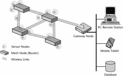
For example, imagine a horse ranch with sensors, each the size of a quarter, dispersed over the land, measuring environmental variables such as temperature and humidity. If each sensor were connected to a base station, the cost would be prohibitive, but in a micromesh network, they are all connected to each other and then to the base station. They synchronize with each other, collect data, and sleep until the next iteration. As illustrated in Figure 15.6, a sensor mesh network must bridge to processing elements that deal with the data collected by sensor nodes. It must also provide monitoring and command and control of the mesh in response to changing conditions. This functionality is best implemented in a gateway. As the size of a micromesh network grows, there is increasing need for a gateway-based systems-level architecture. It is predicted that gateways will become a core element of sensor-mesh networks in the coming years. Figure 15.6. A sensor mesh network
|
|
A WPAN is a network that serves a single person or small workgroup and is characterized by limited distance, limited throughput, and low volume. PANs have traditionally been used to transfer data between a laptop or PDA and a desktop machine or server and a printer. In this case, there is usually support for virtual docking stations, peripheral sharing, and ad hoc infrared links. Another application of WPANs is in support of building automation and control. An increasing number of machine-to-machine (m2m) applications are emerging, as are future applications involving wearables, all of which require PANs to realize their key benefits. As with many of the other technologies discussed so far in this book, there are a variety of PAN standards, some of which are from the IEEE, and some of which are more recent and specifically geared toward m2m communications and sensor-based networks. The IEEE 802.15 WPAN Working Group effort focuses on the development of consensus standards for WPANs. These standards address wireless networking of portable and mobile computing devicessuch as PCs, PDAs, peripherals, mobile phones, pagers, and consumer electronicsallowing these devices to communicate and interoperate with one another. One of the main goals of the working group is to publish standards, recommended practices, and guidelines that have broad market applicability and deal effectively with the issues of coexistence and interoperability with other wired and wireless networking solutions. Four major 802.15 task groups are addressing WPAN standards:
The following sections cover these task groups and the main WPAN standards in use today:
IEEE 802.15.1 (Bluetooth) IEEE 802.15.1, known as Bluetooth, is an industry specification for short-range RF-based connectivity for portable personal devices. This specification was originally developed by Ericsson (www.ericsson.com) and was ultimately formalized by the Bluetooth SIG (www.bluetooth.org), which includes more than 3,000 members, including Sony, Ericsson, IBM, Intel, Toshiba, and Nokia. The IEEE licensed wireless technology from the Bluetooth SIG to adapt and copy a portion of the Bluetooth specification as base material for IEEE 802.15.1-2002. The approved IEEE 802.15.1 standard, which defines the lower transport layers of the Bluetooth wireless technology, is fully compatible with the Bluetooth v1.1 specification. Bluetooth technology defines specifications for small-form-factor, low-cost wireless radio communications among notebook computers, PDAs, mobile phones, and other portable, handheld devices and for connectivity to the Internet. The primary focus of Bluetooth technology is to provide a standard designed for low power consumption, operating over a short range, and including a low-cost transceiver microchip in each device. Bluetooth devices can talk to each other whenever they come within range, with the actual distance allowed depending on the power class of the devices. There are three power classes:
The initial focus of Bluetooth was ad hoc interoperability between mobile phones, headsets, and PDAs, but today it is also seeing application in sensor-based networks. Most Bluetooth devices are recharged regularly. Bluetooth uses FHSS (discussed in Chapter 13) and splits the 2.4GHz ISM band into 79 1MHz channels. Bluetooth devices hop among the 79 channels 1,600 times per second in a pseudorandom pattern. Connected Bluetooth devices are grouped into networks called piconets; each piconet contains one master and up to seven active slaves. The channel-hopping sequence of each piconet is derived from the master's clock. All the slave devices must remain synchronized with that clock. FEC is used on all packet headers, by transmitting each bit in the header three times. The Hamming Code is also used for FEC of the data payload of some packet types. The Hamming Code introduces a 50% overhead on each data packet but is able to correct all single-bit errors and detect all double-bit errors in each 15-bit codeword (each 15-bit codeword contains 10 bits of information). Bluetooth wireless technology is set to revolutionize the personal connectivity market by providing freedom from wired connections for portable handheld devices. The Bluetooth SIG is driving development of the technology and bringing it to market. The IEEE Bluetooth standard gives the Bluetooth SIG's specification greater validity and support in the market and is an additional resource for those who implement Bluetooth devices. This collaboration is a good example of how a standards development organization and a special interest group can work together to improve an industry specification and also create a standard. As of May 2005, 5 million Bluetooth units were shipping per week, demonstrating the wide acceptance of Bluetooth technology in a multitude of applications, such as mobile phones, cars, portable computers, MP3 players, mouse devices, and keyboards. New applications are routinely introduced. For example, one new application involves the digital music kiosks found in thousands of retail locations. These kiosks are beginning to appear with Bluetooth wireless technology, allowing songs to be transferred directly to music-capable mobile phones. Bluetooth wireless technology is the leading short-range wireless technology on the market today. It is now available in its fourth version of the core specification and continues to develop, building on its inherent strengthssmall-form-factor radio, low power, low cost, built-in security, robustness, ease-of-use, and ad hoc networking abilities. Alas, some North American carriers view Bluetooth as a competitive threat. In an attempt to maximize income, these carriers disable file transfer functionality on the Bluetooth-enabled phones they sell, thus requiring users to incur airtime charges associated with e-mailing files to their computers. The Bluetooth SIG has identified several key markets for Bluetooth technology, including automotive, consumer, core technology, computing, and telephony. In addition, Bluetooth wireless technology is beginning to play a major role in wireless seismology and telemetry, adding high-data-rate wireless capability to a sensor market that is estimated at some 1 trillion sensors currently deployed. The growing new generation of wireless sensors will take on many roles, including functions such as monitoring ice on roadways, measuring structural fatigue on bridges, and monitoring beachfronts for pollution and littering. Recently, in keeping with its namesake, Bluetooth came to very positive terms in working with UWB technology (discussed later in this chapter). Demonstrating the next step in the ongoing evolution of WPAN functionality, in January 2006, Alereon (www.alereon.com) hosted the industry's first public demonstration of Bluetooth+WiMedia UWB operating smoothly together under an existing Bluetooth software stack. When it comes to large files and multimedia applications, Bluetooth version 2.0 devices operate at data rates that are frustratingly slow. Bluetooth's maximum data rate of 3Mbps is simply too slow for today's media-centric applications. Combining Bluetooth with WiMedia UWB brings major improvements. The combination of a WiMedia UWB solution from Alereon and Bluetooth software from Open Interface (www.oi-us.com) enables Bluetooth applications that run 500 times the speed of regular Bluetooth and use less than 2% of the battery energy of Bluetooth. Consumers can use this type of solution to share images, phone books, videos, and other Bluetooth content at up to 480Mbps, allowing devices such as megapixel camera phones to download in seconds, rather than minutes. IEEE 802.15.3 (WPAN-HR and WPAN-AHR) The IEEE 802.15.3 (WPAN-HR) Task Group for WPANs was chartered to draft and publish a standard for high-rate (20Mbps or greater) WPANs. Besides a high data rate, the new standard provides for low-power, low-cost solutions that address the needs of portable consumer digital imaging and multimedia applications. IEEE 803.15.3 defines the PHY and MAC specifications for high-data-rate wireless connectivity with fixed, portable, and moving devices within or entering a personal operating space. One goal of the WPAN-HR Task Group is to achieve a level of interoperability or coexistence with other 802.15 task groups. The IEEE 802.15.3 standard has been developed to meet the demanding requirements of portable consumer imaging and multimedia applications, offering QoS to address such environments. It is based on a centralized and connection-oriented ad hoc peer-to-peer networking topology. IEEE 802.15.3 is optimized for low-cost, small-form-factor, and low-power consumer devices, enabling multimedia applications that are not optimized by existing wireless standards. The current technology operates in the unlicensed 2.4GHz band and supports five selectable data rates11Mbps, 22Mbps, 33Mbps, 44Mbps, and 55Mbpsand three to four nonoverlapping channels. The range is 3 to 150 feet (1 to 50 m), with most usage anticipated in the 15- to 60-foot (5- to 20-m) range. The standard is also secure because it implements privacy, data integrity, mutual-entity authentication, and data-origin authentication for consumer applications. The IEEE 802.15.3a (WPAN-AHR) Task Group is working to define a project to provide a higher-speed PHY enhancement to 802.15.3, addressing imaging and multimedia applications. This task group is working on an alternative physical layer for piconets with a 30-foot (10-m) range and for a minimum data rate of 110Mbps. The higher data rates being considered by the 802.15.3a Task Group will enable a host of new applications, including the likes of wireless digital TV, high-definition MPEG-2 motion picture transfer, DVD playback, and digital video camcorders. This 802.15.3a PHY work is currently under consideration. The 802.15.3b Task Group is working on an amendment to 802.15.3 to improve implementation and interoperability of the MAC layer, including minor optimizations, while preserving backward compatibility. The intention is for this amendment to correct errors, clarify ambiguities, and add editorial clarifications. Another interest group (802.15.4IGa) is gathering companies to create a study group to look at support for low-data-rate applications. UWB The term ultra-wideband is often used to refer to anything associated with very large bandwidth, and indeed, one of the reasons UWB is called Ultra-Wideband is that it spreads its signal over a very wide band of frequencies. Depending on the application, the actual frequency band used ranges from 960MHz to 10.6GHz. On a more specific basis, in relationship to radio communications, UWB refers to a technique based on transmitting very short-duration pulses, where the occupied bandwidth is very large, allowing for very high data rates. UWB has a spectrum that occupies a bandwidth greater than 20% of the center frequency, or a bandwidth of at least 500MHz. UWB also uses only a small amount of power and operates in the same bands as existing communications without producing significant interference. Furthermore, UWB is not limited to wireless communications; it can use twisted-pair and coax cables as well, with the potential to transmit data at rates of 1Gbps or faster. Very importantly, UWB complements other longer-range radio technologies, such as Wi-Fi, WiMax, and cellular WANs. It is used to relay data from a host device to other devices in the immediate area (up to 30 feet [10 m]). UWB is like a twenty-first-century version of Marconi's spark-gap transmitter, which was based on short electromagnetic pulses, transmitting a whopping total of 10bps. However, UWB can send more than 100Mbps, with the potential of up to 1Gbps. The basic concept is to develop, transmit, and receive an extremely short-duration burst of radio frequency energy, typically a few tens of picoseconds (trillionths of a second) to a few nanoseconds (billionths of a second) in duration. UWB can not only carry huge amounts of data over a short distance at very low power but also has the ability to carry signals through doors and other obstacles that tend to reflect signals at more limited bandwidths and higher power. Familiar forms of radio communications use what is called a carrier wave. Data messages are impressed on the underlying carrier signal through modulation of the amplitude, frequency, or phase of the wave in some way and then are extracted upon reception. UWB does not employ a carrier wave; instead, emissions are composed of a series of intermittent pulses. By varying the pulses' amplitude, polarity, timing, or other characteristics, information is coded into the data stream. This is similar to the technique used in radar applications. UWB operates at a very low power level, 0.2 milliwatts, thus restricting its range to distances of 300 feet (100 m) or, more typically, as little as 30 feet (10 m). Because the energy levels of the pulses are simply too low to cause problems, interference from UWB transmitters is generally not an issue. A UWB transmitter radiates only 1/3,000 of the average energy emitted by a conventional 600-milliwatt mobile phone, which means it reduces many of the health concerns being expressed and studied in relationship to cellular and PCS networks. Advantages and Disadvantages of UWB UWB offers a number of advantages, including the fact that there is growing demand for greater wireless data capacity, and the crowding of regulated radio frequency spectrum favors systems that offer not only high bit rates but also high bit rates concentrated in smaller physical areas. Given the latest trends toward the use of wireless and mobile communications, a new metric called spatial capacity has evolved. Spatial capacity is a measure of the number of bits per second per square meter that can be supported. Table 15.7 compares the spatial capacities of several commonly used short-range networking technologies.
There are three key factors of interest in selecting a short-range technology: the range over which the technology can operate, how much power it consumes, and the spatial capacity. As you can see in Table 15.7, while 802.11b can operate over a larger coverage area, up to 300 feet (100 m), it can support only 1Kbps per square meter. In a well-attended cafe or hotel lobby, that is not going to provide hotspot users with the capacity needed to work in a multimedia environment. On the other hand, while UWB has a very short range, only 30 feet (10 m), it can support 1,000Kbps per square meter, and it also consumes very little power as an added bonus. Spatial capacity, which is a gauge of data intensity, will be critical to servicing growing number of users in crowded spaces such as airports, hotels, convention centers, and workplaces. UWB is expected to achieve a data rate of 100Mbps to 500Mbps across distances of 15 to 30 feet (5 to 10 m), and it is anticipated that these high bit rates will give birth to applications that are not possible today. It is also expected that UWB units will be cheaper, smaller, and less power-hungry than today's devices. Short-range technology is an ideal way to handle networks of portable (battery-powered) electronic devices, including PDAs, digital cameras, camcorders, audio/video players, mobile phones, laptop computers, and other mobile devices. The growing presence of wired connections to the Internet is another driver of short-distance wireless technology. Many in the developed world already spend most of the day within 30 feet (10 m) of some kind of wired link to the Internet. UWB's precision pulses give it the ability to discern buried objects or movement behind walls. It can also be used to determine the position of emitters indoors. UWB provides a location-finding feature, much like a local version of GPS. UWB capabilities are therefore crucial to rescue and law-enforcement missions. One drawback of UWB is that it is susceptible to interference from other emitters. The ability of a UWB receiver to overcome this problem is sometimes called jamming resistance. This is a key characteristic of good receiver design. Multipath interference is also an issue, and one that also needs to be addressed in the receiver design. UWB Applications Key UWB applications include communications, imaging, telematics, location tracking, and various military and government applications. UWB also has the key attributes necessary to add significant value for consumers of wireless home entertainment and mobile multimedia products. Smart phones, media servers, set-top boxes, flat-panel screens, digital camcorders, and other multimedia applications need a high-data-rate and high-QoS wireless connection to help ensure wire-like performance. UWB applications cover a wide range of scenarios, including the following:
The Future of UWB Proponents of UWB see a future in which UWB technology will reach ubiquity in LANs and PANs. In addition, UWB has the potential to penetrate WAN markets by using ad hoc or managed mesh networks and to eventually make competing technologies such as W-CDMA and GPRS obsolete. UWB could become the dominant technology in WPANs, WLANs, and WWANs. However, a limiting factor to UWB's dominance in the worldwide WAN is unification of global wireless spectrum allocation standards. The greatest challenges UWB faces are regulatory issues and deadlocked UWB standards disputes in the IEEE. Some have raised doubts about the future of UWB. Some industry observers suggest that regulations in Europe will be substantially more restrictive than those applied by the FCC. Japan is likely to be even more conservative. Stiff regulations would limit UWB to a smaller slice of spectrum and reduce its speed and range. It would then have more trouble competing against faster versions of Wi-Fi. In addition, IEEE 802.11n is expected to be established by 2007, offering a theoretical limit of 110Mbps to 200Mbps. Accounting for overhead, the resulting throughput will be some 45Mbps. Although UWB can support 480Mbps at short ranges, it would drop off with distanceparticularly if the regulations limit the spectrum it can use. By the time it goes across a room, the data rate of UWB could be more like that of 802.11n. However, UWB vendors claim that if the lower frequencies are cut out, they can move higher in the spectrum and offer speeds well beyond the currently proposed 480Mbps. Only UWB can promise enough speed to stream HDTV. However, at higher frequencies, there is more absorption, so the effective rangeand the throughput at a given rangeis reduced. Some suggest that that its alliance with Bluetooth may help UWB get regulatory approval. As mentioned earlier in this chapter, the Bluetooth SIG has been working with the developers of UWB to combine the strengths of Bluetooth and UWB. This alliance allows Bluetooth technology to extend its long-term roadmap to meet the high-speed demands of synchronizing and transferring large amounts of data as well as enabling high-quality video applications for portable devices, while UWB benefits from Bluetooth technology's manifested maturity, qualification program, brand equity, and comprehensive application layer. WiMedia In September 2002, nine leading technology companies announced the formation of the WiMedia Alliance (www.wimedia.org). Initial WiMedia Alliance activity was based on the IEEE 802.15.3a (WPAN-AHR) standard, with amendments and enhancements planned for future wireless systems such as UWB. Today, the WiMedia Alliance is a not-for-profit open industry association that promotes and enables the rapid adoption, regulation, standardization, and multivendor interoperability of UWB worldwide. It is dedicated to collaboratively developing and administering specs from the physical layer up, enabling connectivity and interoperability for multiple industry-based protocols. Alliance board members include Alereon (www.alereon.com), Hewlett-Packard (www.hp.com), Intel (www.intel.com), Kodak (www.kodak.com), Microsoft (www.microsoft.com), Nokia (www.nokia.com), Philips (www.philips.com), Samsung Electronics (www.samsung.com), Sony (www.sony.com), STMicroelectronics (www.st.com), Staccato Communications (www.staccatocommunications.com), Texas Instruments (www.ti.com), and Wisair (www.wisair.com). In June 2003, the Multiband OFDM Alliance SIG (MBOA-SIG) was formed to support the development of the best possible technical solution for the emerging UWB (IEEE 802.15.3a) PHY specification for a diverse set of wireless applications. Today, the WiMedia Alliance represents a combination of the original WiMedia Alliance and the MBOA-SIG, the two leading organizations creating UWB industry specifications and certification programs for PC, consumer electronic, mobile, and automotive applications. The combined WiMedia Alliance is an open industry association that defines the WiMedia/MBOA technology. Alliance members consist of industry leaders based in Asia, Europe, and North America. WiMedia defines a UWB common radio platform that enables high speeds (480Mbps and beyond), low power consumption, and multimedia data transfers in a WPAN. It is optimized for several key market segments, including PC, consumer electronic, mobile, and automotive applications. The platform incorporates MAC-layer and PHY-layer specifications based on Multiband OFDM (MB-OFDM). ECMA-368 and ECMA-369 are international ISO-based specifications for the WiMedia UWB common radio platform (see www.ecma-international.org). WiMedia now includes the MBOA UWB technologies that will permit the long battery life that is key for mobile applications. The Wireless USB Promoter Group (www.usb.org/developers/wusb) has endorsed WiMedia as a common platform for its next-generation wireless implementations. The 1394 Trade Association (TA) Wireless Working Group (www.1394ta.org) has approved WiMedia's MAC Convergence Architecture (WiMCA) as a platform for a high-speed wireless IEEE 1394 (FireWire) protocol adaptation layer (PAL) development. The 1394 TA also said it will collaborate with the WiMedia Alliance to develop interoperability test specifications and certification programs for wireless IEEE 1394. WiMedia also plans to develop universal IP addressing protocols in alignment with organizations such as the UPnP Forum (www.upnp.org) and the Digital Living Network Alliance (DLNA; www.dlna.org). In addition, as mentioned earlier, January 2006 saw the successful demonstration of Bluetooth+WiMedia UWB operating smoothly together under an existing Bluetooth software stack. UWB technology has the inherent capability to optimize wireless connectivity between multimedia devices within a WPAN. The WiMedia UWB common radio platform is unique in that no other existing wireless standard can fulfill the market's stringent requirements, such as low cost, low power consumption, small form factor, high bandwidth, and multimedia QoS support. IEEE 802.15.4 (ZigBee) At the end of the 1990s, many engineers began to see that Bluetooth and Wi-Fi, while excellent short-range solutions, were not the best solutions for some applications, particularly self-organizing ad hoc networks of various industrial controls, building and home automation devices, security and smoke alarms, and medical devices. With inspiration from the simple one-chip design of Bluetooth radios, a community of like-minded engineers began the development of ZigBee, a wireless communication protocol designed for small building devices. The IEEE 802.15.4 standard, completed in May 2003, defines the technical specifications of the PHY and MAC layers for ZigBee. The IEEE 802.15.4 specification is mainly designed for command and control, for which a 200Kbps data rate is more than adequate. The IEEE 802.15 Task Group 4 (TG4; www.ieee802.org/15/pub/TG4.html) was chartered to investigate a solution with several key characteristics: a low data rate with a very long battery life (months to even years) and very low complexity. ZigBee operates, internationally, in the unlicensed frequency bands. Potential applications for ZigBee include sensors, interactive toys, smart badges, remote controls, and home and building automation tools. The ZigBee 1.0 specifications were ratified in December 2004, and version 1.1 is now in the works. As with many of the other WPAN technologies, there are relationships between the formal IEEE task group and the representative industry alliancein this case between 802.15 TG4 and the ZigBee Alliance (www.zigbee.org). The ZigBee Alliance, formed in October 2002, is a nonprofit industry consortium of companies working together to enable reliable, cost-effective, low-power, wirelessly networked monitoring and control products based on an open global standard. The member companies are working together to develop standardized application software on top of the IEEE 802.15.4 standard. The goal of the ZigBee Alliance is to give consumers the most flexible building systems available by introducing the ZigBee wireless technology into a number of building devices. As of mid-December 2005, the ZigBee Alliance membership had surpassed 200 member companies from 24 countries spanning six continents, with OEMs and end product manufacturers representing over 30% of the global membership. The ZigBee Alliance focuses on four main areas: defining the network, security, and application software layers of the protocol; providing interoperability and conformance testing for ZigBee devices; promoting the ZigBee brand globally; and managing the evolution of the technology. ZigBee Devices and Networks ZigBee was created to support wireless communications between devices without the expense of having to run wires between them. ZigBee's benefits include flexibility and scalability, reduction in design and installation time, interoperability, longer battery life, and low cost. It is made for two-way communication among devices and can be used to build a general-purpose, inexpensive, self-organizing network of devices. This protocol opens the door to the flexibility and benefits of interoperability. Because ZigBee uses open standards, it reduces the costs and risks associated with building the technology into devices. ZigBee is a short-range, low-power protocol specifically designed for small building devices such as thermostats, lighting controls, ballasts, environmental sensors, and medical devices. It is meant to offer short-distance, low-speed transmissions that require little power. As a result, the battery life of ZigBee devices can range from six months to two years or longer, using only a single alkaline battery. There are three types of ZigBee devices:
A ZigBee network is capable of supporting up to 254 FFDs, 1 coordinator, and potentially thousands of RFDs. Most importantly, because the ZigBee protocol expects most messages to receive acknowledgments in order to verify successful reception, all devices are transceivers (i.e., they transmit and receive). Figure 15.7 shows an example of a ZigBee home network. Figure 15.7. An example of a ZigBee home network
ZigBee devices operate in unlicensed spectrum worldwide and are based on DSSS technology. They operate at the maximum data rates shown in Table 15.8, and their transmission range is 30 to 250 feet (10 to 75 m).
The ZigBee standard is designed to provide reliable data transmission of modest amounts of data up to 250 feet (75 m) while consuming very little power. It also offers support for critical-latency devices, such as joysticks. ZigBee offers lower power consumption, lower cost, higher density of nodes per network, and simplicity of protocols compared with other wireless connectivity schemes. Because ZigBee's topology allows as many as 254 nodes per network, it is ideal for industrial applications. ZigBee is the only standards-based technology designed to address the unique needs of low-cost, low-power, wireless sensor networks for remote monitoring, home control, and building automation network applications in the industrial and consumer markets. ZigBee supports three network topologies:
The Future of ZigBee Future applications of the ZigBee protocol include its use in tracking and asset management systems, generators, elevators, and so on, gathering data that can be transformed into viable information and enabling users to run their businesses more efficiently. The IEEE 802.15.4 group says that one day it might be common to find 50 ZigBee radio chips in a house. Those chips could serve duty in a home's 10 to 15 light switches, several fire and smoke detectors, thermostats, 5 or 6 toys and interactive game machines, and other human input devices. Radio-frequency-based ZigBee will eventually replace all the infrared (IR) links at home. ZigBee is not designed for video or CD-quality audio, but it could be used to send text or voice messages. No QoS provision is built into ZigBee. In January 2006, the ZigBee Alliance announced its ZigBee Certification program, which ensures that products are fully interoperable out of the box and can easily participate in a ZigBee network. Member companies can now test the growing number of ZigBee-ready products already on the consumer market so they can be fully branded as ZigBee Certified for home, industrial, or commercial use. Independent test service providers will oversee and conduct the ZigBee Alliance's certification testing to ensure that products are interoperable in a variety of environments and end-user applications. RFID RFID is a method of remotely storing and retrieving data by using devices called RFID tags. An RFID tag is a small object that can be attached to or incorporated into a product, an animal, or a person and then read by an RFID reader. The origins of RFID technology take us back to the early 1920s, when MIT developed a similar technology as a way for robots to talk to one another. The first known device that has been recognized as a predecessor to RFID technology was a passive covert listening device invented in 1945 by Leon Theremin to be used as an espionage tool for the Soviet government. A similar technology, called Indentification Friend or Foe (IFF), was invented by the British in 1939 and used extensively by the Allies during World War II to identify and authenticate allied planes and other vehicles. RFID is being used today for the same purposes. However, it is now also recognized that an investment in RFID technology can improve the efficiency of many enterprise operations, reduce errors, and improve on operating costs. With RFID, any movable item or asset can be identified and tracked better and more efficiently. The first RFID systems deployed for tracking and access applications entered the marketplace during the 1980s. As the technology matures, it is clear that we can expect more pervasive and most likely more invasive applications for RFID. Industry analysts predict explosive growth for RFID over the next several years, forecasting that by 2010, there will be some 33 billion tags produced, compared to just 1.3 billion in 2005. Retail, automotive, and pharmaceutical companies are expected to lead in the adoption of RFID. Several organizations are involved in drafting standards for RFID technology. Both the ISO (www.iso.org) and EPCglobal (www.epcglobalinc.org) have had many initiatives related to RFID standards. EPCglobal is an important organization to the RFID movement: It is leading the development of industry-driven standards for the electronic product code (EPC) to support the use of RFID in today's fast-moving, information-rich trading networks. It is a subscriber-driven organization comprising industry leaders and organizations, focused on creating global standards for the EPCglobal network. Currently, the purpose of an RFID system is to allow a tag to transmit data to an RFID reader, which then processes the data according to the application requirements. The information transmitted can provide identification or location data and can also include more specific information, such as date of purchase, price, color, size, and so on. RFID tags are envisioned as a replacement for universal product code (UPC) barcodes because they have a number of important advantages over the older barcode technology. RFID codes are long enough that every RFID tag may have a unique code, whereas UPC codes are limited to a single code for all instances of a particular product. The uniqueness of RFID tags means that a product may be individually tracked as it moves from location to location, finally ending up in the consumer's hands. This may help to combat theft and other forms of product loss. It has also been proposed to use RFID for point-of-sale store checkout to replace the cashier with an automatic system, with the option of erasing all RFID tags at checkout and paying by credit card or inserting money into a payment machine. Other innovative uses have also been proposed, such as allowing a refrigerator to track the expiration dates of the food it contains. How an RFID System Works RFID systems are composed of several components: tags, readers, edge servers, middleware, and application software. The key element of RFID technology is an RFID transponder, usually called a tag. An RFID tag is a small object, such as an adhesive sticker, that can be attached to or incorporated into an object (anything from a pallet of laundry detergent to a racecar tire to a pet's neck). An RFID tag is a tiny microchip composed of a processor, memory, and a radio transmitter that is mounted onto a substrate or an enclosure. The amount of memory varies from just a few characters to kilobytes. An RFID tag's antenna enables it to receive and respond to radio frequency queries from an RFID reader, also known as a transceiver or an interrogator, which has its own antenna. Here's how an RFID system works (see Figure 15.8):
Figure 15.8. An example of an RFID system
No contact or even line of sight is needed to read data from a product that contains an RFID tag. RFID technology works in rain, snow, and other environments where barcode or optical scanning technology is useless. RFID Tags Different types of RFID tags address different applications requirements:
In addition, RFID tags can be either active or passive. Active RFID tags must have a power source but have longer ranges of operation and larger memories than passive tags, providing the ability to store additional information sent by the reader. Active tags, about the size of a dime and designed for communications up to 100 feet (30 m) from the RFID reader, are powered by a battery and are always on. They are larger and more expensive than passive RFID tags but can hold more data about the tagged object and are commonly used for high-value asset tracking. Active RFID tags can be read/write. Many active tags have practical ranges of tens of meters and a battery life of up to 10 years. One of the most common applications for active tags is in the transportation sector (e.g., for highway tolls). Passive RFID tags do not have their own power supplies or batteries. Instead, the minute electrical current induced in the antenna by the incoming RF scan from the reader provides enough power for the tag to send a response. The received signal charges an internal capacitor on the tag, which in turn supplies the power required to communicate with the reader. Because passive tags do not contain power supplies, they can be much smaller than active tags and have an unlimited life span. As of 2006, the smallest commercially available passive tags measured just 0.3 mm across and were thinner than a sheet of paper, making them just about invisible. Due to its power and cost, the response of a passive RFID tag is generally brief, typically just an ID number. Passive RFID tags can be read from a distance of about 20 feet (6 m). A semipassive RFID tag contains a small battery that boosts the range. Passive tags are generally read-only, so the data they contain cannot be altered or written over. Some of the most common uses of passive RFID include animal identification, waste management, security and access control, work-in-process, asset tracking, and electronic commerce. The Chek Lap Kok airport in Hong Kong uses passive RFID tags to track the movement of every piece of luggage that passes through the baggage-handling system. Because passive tags are cheaper to manufacture than active tags, the majority of RFID tags in existence today are the passive type. As of 2006, passive tags, when bought in high volumes, cost an average of US$0.24 each. With volumes of 10 million units or more, the cost can drop to around US$0.07 per tag. The goal is to produce tags for less than US$0.05 to make widespread RFID tagging commercially viable. The main benefits of RFID include the fact that tags can be read from a distance and from any orientation, so they do not require line-of-sight conditions in order to be read. Read/write tags offer the additional benefit of allowing data to be changed dynamically at any time. Another benefit of RFID is that multiple tags can be read at the same time and in bulk very quickly. Finally, the tags can be easily embedded into any nonmetallic object, enabling the tags to work in harsh environments and providing permanent identification for the life of the object. However, the environment into which RFID will be implemented must be carefully considered because factors such as the presence of metal, electrical noise, extreme temperatures, liquids, and physical stress may affect performance. RFID Readers RFID readers are used to query RFID tags in order to obtain identification, location, and other information about the object the tag is embedded in. In addition, the reader antenna sends RF energy to the RFID tag antennas, which use that energy to power up the microchip. There are two types of RFID readers:
RFID Frequencies Even though no global body currently governs RFID frequencies (each country can set its own rules), there are four main frequency bands for RFID tags, as shown in Table 15.9.
LF and HF can be used globally without a license. UHF cannot be used globally because there is no single global standard. Despite the availability of various bands in which RFID can operate, there is not just one that can address all applications. Each band has specific attributes that make it suitable for different applications. LF RFID The reading range of LF RFID can vary from a few centimeters to a couple meters, depending on the size of the tags and the reader being used. One of the key features of LF RFID is that it is not as affected by surrounding metals as other types of RFID, making it ideal for identifying metal items such as vehicles, equipment, tools, and metal containers. The largest user for LF RFID is the automotive industry. A car key has an LF tag embedded in it that works with a reader mounted in the ignition. Other automotive applications include vehicle identification for highway and parking lot access. LF RFID penetrates most other materials, such as water and body tissue, which makes it ideal for animal identification (for endangered species and for pets and livestock) and beer keg tracking. The limitations of LF RFID are that if used in industrial environments, electric motors may interfere with the LF system. Due to the size of the antenna required, LF tags are typically more expensive than HF tags, which limits LF to applications where the tags can be reused. However, LF is used worldwide, and there are no restrictions on its use. HF RFID Passive HF, at 13.56MHz, is a globally accepted frequency, which means any system operating at HF can be used globally. However, there are some differences between the regulations in the different regions of the world, related primarily to power and bandwidth. In North America, the FCC limits the reader antenna power to 3 watts, while European regulations allow for 4 watts. HF is also the basis of numerous standards, such as ISO 14443, 15693, and 18000-3. With HF, the signal travels well through most materials, including liquid and body tissue. However, it is more affected by surrounding metals than LF. In comparison to LF, the benefits of HF are lower tag costs, better communication speed, and the ability to read multiple tags at once. The higher the frequency, the higher the data throughput and the faster the communications between the tags and the reader, and at HF, a reader can read up to 50 tags per second. The increase in speed also allows for the reader to communicate with multiple tags at the same time. HF RFID tags are used in book tracking for libraries and bookstores, pallet tracking, building access control, airline baggage tracking, apparel item tracking, and identification badges. UHF RFID Whereas HF and LF work fairly well in the presence of liquids, today's UHF systems do not work in such environments. Metal poses a serious challenge for any RFID implementation, but especially in the UHF range. Moreover, the longer read distance of UHF is a disadvantage in applications such as banking and access control. However, its high data throughput facilitates higher read rates, with 800 reads per second possible in theory, although 200 reads per second is closer to reality. UHF RFID tags are commonly used commercially to track pallets and containers as well as trucks and trailers in shipping yards, and UHF vendors are targeting the supply-chain market, where longer read distances are required. UHF tags can be used globally when they are specially tailored according to regional regulations because there are no globally unified regulations for radio frequencies in this ISM band range. However, one of the biggest challenges that has impeded the widespread implementation of UHF RFID is lack of globally accepted standards and regulations. Different frequency designations and power and safety regulations are in place in different regions of the world. In North America, UHF operates at 902MHz to 928MHz; in Europe, it works in the 860MHz to 868MHz range; and in Japan, it operates at 950MHz to 956MHz. EPCglobal (www.epcglobalinc.org) worked through 2004 to pave the way for ratification of the UHF Generation 2 Air Interface Protocol (commonly referred to as the Gen2 standard) by driving regulatory agenciesfrom the ETSI to Japan's Ministry Post and Telecomto open bandwidth in the UHF spectrum so RFID could operate seamlessly through supply chains across continents. Gen2, which was ratified as an EPCglobal standard in December 2004, has been accepted by the ISO. Some of the requirements for this standard include convergence to one global, interoperable standard; increased speed and ease of global adoption; increased functionality and performance; and increased production and competition. Gen2 is heralded as the first UHF RFID open architecture designed by a committee. Many supply-chain benefits depend on Gen2: global interoperability, international vendor support, multiple read and write capabilities that could potentially change the economic climate by delivering a quicker return on investment, and increased data communication speeds more than double those of the tags available today. The read rate for Gen2 tags in the United States under a simulated environment is 1,500 per second, versus roughly 100 tags per second for tags available today. (The read rate for Gen2 tags in Europe, however, is only 500 to 600 tags per second because U.S. regulations allow for wider frequency bandwidth.) As the industry switches to Gen2, many companies will face huge conversion costs. On the other hand, because Gen2 establishes interoperability and bandwidth technologies, it is anticipated that Gen2 will boost adoption of RFID. Microwave RFID Microwave RFID tags are used in long-range access control for vehicles, such as GM's OnStar system. Additional microwave RFID applications include electronic highway toll collection; reading of seismic activity, greatly simplifying remote data collection; and vehicle tire tracking. RFID Privacy There are some major privacy concerns regarding RFID use, including the following:
Most concerns revolve around the fact that RFID tags affixed to products remain functional even after the products have been purchased and taken home and thus can be used for surveillance and other nefarious purposes unrelated to their supply-chain inventory functions. Although RFID tags are only officially intended for short-distance use, they can be interrogated from greater distances by anyone who has a high-gain antenna, potentially allowing the contents of a house to be scanned at a distance. Even short-range scanning is a concern if all the items detected are logged in a database every time a person passes a reader, or if it is done for nefarious reasons, such as a mugger using a handheld scanner to obtain an instant assessment of the wealth of potential victims. With permanent RFID serial numbers, an item leaks unexpected information about a person even after disposalfor example, items being resold or given away enable mapping of a person's social network. Another privacy issue has to do with RFID's support for a singulation (i.e., anticollision) protocol. This is the means by which a reader enumerates all the tags responding to it without them mutually interfering. The structure of the most common version of this protocol is such that all but the last bit of each tag's serial number can be deduced by passively eavesdropping on just the reader's part of the protocol. Because of this, whenever RFID tags are near readers, the distance at which a tag's signal can be eavesdropped is irrelevant; what counts is the distance at which the much more powerful reader can be received. Just how far this is depends on the type of the reader, but in the extreme case, some readers have a maximum power output of 4 watts, which could be received from tens of kilometers away. Rarely is information encrypted between a tag and the reader. This creates opportunities for malicious people to eavesdrop on communications and reuse them in nefarious waysfor instance, quickly and easily duplicating a passport. Similarly, there is no standard authentication protocol between a tag and the reader. Again, considering the passport as an example, it is currently possible to conduct a man-in-the-middle attack between a tag-equipped passport and the reader on the desk of the passport control officer. An attacker could substitute information on-the-fly, possibly circumventing detention in one case while making life very difficult for some other innocent citizen standing in line. Fortunately, governments are starting to realize the risks associated with electronic passports and are examining security controls to mitigate such risks. EPCglobal's Gen2 standard includes privacy-related guidelines for the use of RFID-based EPCs. The Guidelines on EPC Usage for Consumer Products were adopted as a basic framework for responsible use and deployment of EPC (see www.epcglobalinc.org/public_policy/public_policy_guidelines.html). These guidelines include the requirement to give consumers clear notice of the presence of EPCs and to inform them of the choice they have to discard, disable, or remove EPC tags. It is crucial that we ensure that RFID technology is used to improve our lives and our business practices without intruding on privacy. To this end, governments, the private sector, and other agencies must safeguard principles of informed consent, data confidentiality, and security; courts and governments around the world are now in the process of determining related legal issues. The Electronic Privacy Information Center (EPIC) has a great deal of additional information about RFID privacy as well as interesting projects on its Web site (www.epic.org/privacy/rfid). The Future of RFID It appears that RFID is well on its way to becoming a large part of our lives. More than 1.3 billion RFID tags were produced in 2005, and that figure is expected to soar to 33 billion by 2010 (In-Stat, "RFID Tags and Chips: Opportunities in the Second Generation," www.instat.com, January 18, 2006). Production will vary widely by industry segment for several years. For example, RFID has been used in automotive keys since 1991, with 150 million units now in use. This quantity greatly exceeded other segments until recently. By far the biggest RFID segment in coming years will be supply-chain management. Wal-Mart, the world's largest retailer, has spurred this projected growth by mandating that its top 100 (and then its top 300) suppliers use RFID at the pallet/case level. The spread and use of RFID in most sectors will be largely determined by cost, and the costs of RFID tags and labels are dropping quickly. Pharmaceutical companies are investigating using RFID tags to reduce counterfeiting and black-market sales. Other market segments expected to incorporate the use of RFID include livestock, domestic pets, humans, cartons/supply-chain uses, large freight containers, package tracking, consumer products, and security/banking/purchasing/access control. But will RFID replace UPC barcode technology? Most likely not, and certainly not in the near term. RFID tags still cost more than UPC labels, and different data capture and tracking technologies offer different capabilities. Many businesses will likely combine RFID with existing technologies such as barcode readers or digital cameras to achieve expanded data capture and tracking capabilities that meet their specific business needs. NFC In the midst of the various WPAN technologies discussed so far in this chapter, a new technology is quietly taking shape that could alter the use of consumer electronics and change the way users shop, travel, and send data. Near Field Communication (NFC) evolved from a combination of RFID, interconnection (i.e., information exchange via network technology), and contactless identification technologies. (With contactless identification, a smart card has an antenna embedded inside it, enabling communication with a card reader without physical contact. The chip on the smart card stores data and programs that are protected by advanced security features. Contactless smart cards are passed near an antenna, or reader, to carry out a transaction.) With NFC-enabled mobile phones, transactions can be conducted by simply touching a point-of-sales device or ticket gate. Contactless cards are the ideal solution for transactions that must be processed very quickly, as in physical access control, mass transit, or vending services. NFC provides high-bandwidth content acquisition and transfer, contactless payment capability, and smart object interaction. One of the key attributes of NFC is that it introduces convenience to increasingly connected digital consumers, allowing new genres of interactions with interactive advertising posters and kiosks, instant ticketing, and the transmission of audio, pictures, and video. NFC technology is showing tremendous promise for transforming consumer commerce, connectivity, and content consumption, enhancing end-user experiences while redefining communications, content, and payment business models. NFC is expected to be deployed beginning in 2007, first in wireless handsets and then in other kinds of consumer electronics, from PCs to cameras, printers, set-top boxes, and the growing range of smart devices. The success of NFC depends on open, interoperable, standards-based NFC environments. To help in this quest, the NFC Forum (www.nfc-forum.org) is adding fuel to the technology's expansion. The NFC Forum was founded by Nokia (www.nokia.com), Philips (www.philips.com), and Sony (www.sony.com) in 2004, and since then, dozens of companies have signed up for the industry group. The NFC Forum now boasts more than 60 collaborating members, including wireless carriers, handset OEMs, application developers, payment processors, infrastructure providers, content owners, card issuers, and banks and merchants. NFC is standardized in a number of ISO, Ecma International, and ETSI standards, providing for maximum flexibility as the technology seeks compatibility with existing devices, especially smart cards. NFC, a short-range, contactless communications protocol, enables easy-to-use, secure connectivity between devices. It can also be used to configure and initiate other wireless network connections, including Bluetooth and Wi-Fi. It is a wireless technology that operates in the globally available and unregulated 13.56MHz frequency band, over a typical distance of a few centimeters, but with a maximum working distance of 5 to 6.5 feet (1.5 to 2 m). It supports three data transfer rates: 106Kbps, 212Kbps, and 424Kbps. By using magnetic field induction, NFC allows two devices embedded with chips to exchange information by being in close proximity. There are no intermediate devices, which means NFC acts as a peer-to-peer transmission. NFC enables a handset or mobile device to act as a contactless transfer medium. NFC chips will be embedded in a variety of devices, allowing the exchange of information within a very short distance. This makes for a very intuitive pairing of devices with a minimal authentication process. There are three modes of operation:
Nokia and Motorola have both introduced devices supporting the technology, and they are designed in part to serve as payment devices. Nokia has an NFC-enabled phone available, the 3220. With the Nokia NFC shell, this handset allows consumers access to browsing and text message services simply by touching tags that contain service shortcuts. The NFC-enabled phone can be used as a loyalty card, credit card, or train or bus ticket. Purchases normally made with a credit card can be made with the phone because the phone is, in fact, a credit card. NFC will find uses in areas such as e-ticketing, where the customer holds his or her mobile phone close to the ticket kiosk to start the transaction. The customer interacts with the service and then completes the purchase by confirming the transaction on the NFC-enabled mobile phone. Arriving at the concert hall, the customer then holds his or her mobile phone close to a reader fitted to the entrance turnstile, which allows access after the reader checks the validity of the ticket. Each NFC device has the potential to replace a wallet full of credit cards, which is a liability if it falls into the wrong hands. NFC proponents are quick to note that a lost or stolen mobile phone can be disabled with a single call to the service provider, but canceling a wallet full of credit and bank cards requires at least an hour. One of the most important things to be aware of is that NFC security is a matter of accepting or not accepting a message from another device. Users must therefore constantly be aware of the status of their devices, and know, for example, whether they are configured to automatically connect with nearby NFC devices. There are also some threats unique to NFC, as well as opportunities for clever thieves. For example, as RFID chips and readers become more pervasive, we can imagine a new technique emerging, something being referred to as billboard phishing, where the impersonator could possibly paste posters, with embedded phony RFID chips, over kiosks, posters, or turnstiles. In this case, how is the user to know whether what they are touching is fake or legitimate? As with RFID technology, security professionals need to help shape the security policies and protocols that might affect device authentication and other issues. To this end, the NFC Forum has formed a security workgroup to develop industry standards. NFC technology is currently being used extensively in Asia and the Pacific, and it is being used less in Europe and even less in the United States. However, we can expect to see NFC expand rapidly, especially in payment transaction scenarios and public transportation. |
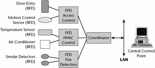
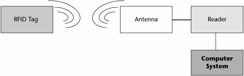
Part I: Communications Fundamentals
Telecommunications Technology Fundamentals
- Telecommunications Technology Fundamentals
- Transmission Lines
- Types of Network Connections
- The Electromagnetic Spectrum and Bandwidth
- Analog and Digital Transmission
- Multiplexing
- Political and Regulatory Forces in Telecommunications
Traditional Transmission Media
Establishing Communications Channels
- Establishing Communications Channels
- Establishing Connections: Networking Modes and Switching Modes
- The PSTN Versus the Internet
The PSTN
- The PSTN
- The PSTN Infrastructure
- The Transport Network Infrastructure
- Signaling Systems
- Intelligent Networks
- SS7 and Next-Generation Networks
Part II: Data Networking and the Internet
Data Communications Basics
- Data Communications Basics
- The Evolution of Data Communications
- Data Flow
- The OSI Reference Model and the TCP/IP Reference Model
Local Area Networking
Wide Area Networking
The Internet and IP Infrastructures
- The Internet and IP Infrastructures
- Internet Basics
- Internet Addressing and Address Resolution
- The Organization of the Internet
- IP QoS
- Whats Next on the Internet
Part III: The New Generation of Networks
IP Services
Next-Generation Networks
- Next-Generation Networks
- The Broadband Evolution
- Multimedia Networking Requirements
- The Broadband Infrastructure
- Next-Generation Networks and Convergence
- The Next-Generation Network Infrastructure
Optical Networking
- Optical Networking
- Optical Networking Today and Tomorrow
- End-to-End Optical Networking
- The Optical Edge
- The Optical Core: Overlay Versus Peer-to-Peer Networking Models
- The IP+Optical Control Plane
- The Migration to Optical Networking
Broadband Access Alternatives
- Broadband Access Alternatives
- Drivers of Broadband Access
- DSL Technology
- Cable TV Networks
- Fiber Solutions
- Wireless Broadband
- Broadband PLT
- HANs
Part IV: Wireless Communications
Wireless Communications Basics
- Wireless Communications Basics
- A Brief History of Wireless Telecommunications
- Wireless Communications Regulations Issues
- Wireless Impairments
- Antennas
- Wireless Bandwidth
- Wireless Signal Modulation
- Spectrum Utilization
Wireless WANs
- Wireless WANs
- 1G: Analog Transmission
- 2G: Digital Cellular Radio
- 5G: Enhanced Data Services
- 3G: Moving Toward Broadband Wireless
- Beyond 3G
- 4G: Wireless Broadband
- 5G: Intelligent Technologies
WMANs, WLANs, and WPANs
- WPANs
Emerging Wireless Applications
- Emerging Wireless Applications
- The Handset Revolution
- Mobile IP
- The IP Multimedia Subsystem
- Mobile Gaming
- Mobile Video
- Mobile TV
- Mobile Content
Glossary
EAN: 2147483647
Pages: 160
