The Optical Core: Overlay Versus Peer-to-Peer Networking Models
The Optical Core Overlay Versus Peer to Peer Networking Models
Today's advanced networks maintain mostly separate electronic connections for voice and data and achieve reliability by using rings based on the SDH/SONET communication standard. In this configuration, if one link is cut, traffic flows down the other half of the ring. The SDH/SONET multiplexer aggregates the traffic onto the ring, so there's a stack, or hierarchy, of rings, depending on the scope of the network they're serving (refer to Figure 11.1).
In the local realm, which might be a small city or metro area environment, traditionally the rings are based on a capacity of OC-12, or 622Mbps. For slightly larger-scale rings, such as regional rings, OC-48, or 2.5Gbps, is often the capacity. Core backbone rings provide OC-192, or 10Gbps. Currently, as metro capacity requirements are increasing, we're migrating from OC-12 to OC-48. Similarly, some of the regional rings are migrating from OC-48 to OC-192, and we're looking at ways to expand the capacity of the backbone core, generally through the addition of dense wavelength division multiplexers, which allow multiple 10Gbps streams to coexist on one fiber. Although some systems can now offer up to 40Gbps, they are in early stages of deployment.
Rather than using rings, tomorrow's networks will channel all traffic over the same fiber connection and will provide redundancy by using the Internet's mesh approach of interlocking pathways. In that case, when a line breaks, traffic can flow down several alternating pathways. Optical switches will be the foundation for building these integrated networks. Optical switches all have point-to-point links between them (refer to Figure 11.2). If there is a failure in a given link or node, traffic can be quickly rerouted over any other alternative in the network configuration.
There are several problems with the first generation of optical networks. Bandwidth efficiency is an issue at the higher capacities of SDH/SONET. The SDH/SONET hierarchy is not optimized for large data transfers, mainly because it is a single-wavelength solution. SDH/SONET is a TDM scheme, so it does not take advantage of WDM and the resident ability to carry multiple wavelengths (hundreds today and thousands in the future). As a result, operators have to manage two layers todaySDH/SONET and WDMand riding on top of those, both Layer 2 and Layer 3 networks.
To enable a network to request additional capacity to accommodate changes with very large traffic flows, two approaches are emerging:
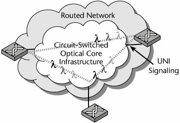
- The overlay model The overlay model, shown in Figure 11.12, calls for maintaining two discreet and separately provisioned networks: a Layer 1 optical network and the client network. In this model, devices reside at the edge of the network cloud, and core network infrastructure is hidden from the routed network. The overlay model relies on the User-to-Network Interface (UNI) for signaling at the edge. The ITU and ANSI support this model. The traditional voice carriers are driving the development of a protocol that will transport all types of traffic: nonvoice over SDH/SONET as well as its high-speed successor, the Optical Transport Network (OTN). The OTN would operate across a new standard, the Automatic Switched Optical Network (ASON). (The OTN and ASON are described later in this chapter.)
Figure 11.12. The overlay model
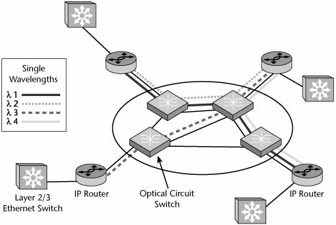
- The peer-to-peer model The peer-to-peer model, shown in Figure 11.13, argues for a single network in which the equipment on the network edge decides how bandwidth is allocated within the network's core. The network is fully visible to all devices, but edge devices need to know about only their closest optical switches. Routers and optical switches are peers in this model. This approach is promoted by the data community, including the IETF and the IEEE. This IP-centric approach is based on Generalized Multiprotocol Label Switching (GMPLS). GigE and 10GigE are promoted as solutions for the near to mid-term, with the long term possibly focusing on Resilient Packet Ring.
Figure 11.13. The peer-to-peer model
The following sections describe these two approaches to the optical core in more detail.
The Overlay Model
The overlay model, formally known as the OTN and promoted by the ITU and carrier communities, is characterized by devices residing on the edge of the cloud, the core network infrastructure being hidden from the routed network, and relying on UNI for signaling at the edge.
The ITU's next generation of optical networks is specified under a number of recommendations, including G.872, G.709, and G.959.1. The OTN defines a new network hierarchy, the optical transport hierarchy, whose base unit is the optical transport module (OTM), which has a 64-byte frame. The OTN comprises all optical elements. The initial clients of the OTN are SDH/SONET and data services, including Ethernet, IP, ATM, and Fibre Channel. Management capabilities are defined for conductivity verification, performance assessment, and fault sectionalization.
The OTN has three main elements:
- Optical channel The optical channel is similar to SDH/SONET's path component. It defines the logical connection between stations or end-to-end networking, and it transports clients' signals between two endpoints on the OTN.
- Optical multiplex section The optical multiplex section, which is similar to SDH/SONET's line component, describes the WDM portions that underpin the optical channels and consists of many aggregated optical channels.
- Optical transmission section The optical transmission section is similar to SDH/SONET's section component. It defines a physical interface that details optical parameters such as frequency, power level, and signal-to-noise ratio.
The OTN reaches higher speeds by bundling wavelengths. OTMs, which can span multiple wavelengths of different capacities, are described with two suffixes: n refers to the maximum number of wavelengths supported at the lowest bit rate on the wavelength, and m indicates the bit rate supported on the interface. Together, these are written as OTM n.m. The OTN supports optical signals with three bit rates: When m equals 1, it refers to 2.5Gbps; when it is 2, it refers to 10Gbps; and when it is 3, it refers to 40Gbps. An interface can support combinations of these rates. For example, OTM 3.2 indicates a channel that spans three wavelengths, each operating at least at 10Gbps. OTM 5.12 indicates a channel that spans five wavelengths and can operate at either 2.5Gbps or 10Gbps.
ASON and ASTN
The OTN differs from today's networks in the types of services it can offer. Instant provisioning requires a signaling protocol to set up the paths or connections so that data can be transported. Work on SDH/SONET and OTN signaling is being defined in two ITU ANSI specifications:
- Automatic Switched Optical Network (ASON) ITU G.8080 describes ASON, the set of control plane components used to manipulate transport network resources in order to provide the functionality of setting up, maintaining, and releasing connections. ASON is described further later in this chapter, at the end of the section "The IP+Optical Control Plane."
- Automatic Switched Transport Network (ASTN) ITU G.807 describes ASTN, which allows traffic paths to be set up automatically through a switched network. ASTN is often used interchangeably with GMPLS. ASTN allows the user to specify the start point, endpoint, and bandwidth required. ASTN/GMPLS consists of several protocols, including routing protocols (OSPF-TE or IS-IS-TE), Link Manangement Protocol (LMP), and reservation/label distribution protocols (RSVP-TE and CR-LDP). ASTN consists of clients, with each level seeing a differing degree of network detail. Clients can be multiplexers or WDM systems, as well as Ethernet switches or other devices that implement Generic Framing Procedure (GFP), a unifying data link for both SDH/SONET and OTN networks. ANSI's GFP T1X1.5a is an SDH/SONET subprotocol that provides a standard means for packing voice traffic into an SDH/SONET frame, enabling equipment interoperability.
Clients connect to the network through one of three types of network interfaces:
- User-to-Network Interface (UNI) The UNI defines how customers can access their providers' networks. It is used to request capacity from the underlying network and shields the client from network complexities. Minimal information is provided; the UNI provides only the name and address of the endpoint, the authentication and admission control of the client, and connect service messages.
- External Network-to-Network Interface (E NNI) The E NNI provides summarized network address information along with authentication and admission control and connection service messages. The partner does not know the exact paths, but it does know the available clients that can be called. This is analogous to an electronic address book provided by one carrier to the next of all the available nodes.
- Internal Network-to-Network Interface (I NNI) The I NNI enables devices to get topology or routing information for the carriers' network, as well as connection service messages and information necessary to optionally control network resources.
Clients can request three types of circuits in ASTN. First, provisioned circuits are hard or permanent circuits much like a leased line, also known as a permanent connection. Second, signaled circuits are established dynamically by the endpoint requesting bandwidth. This requires network addressing information and is known as a switched connection. Finally, hybrid circuits are a cross between provisioned and signaled circuits. They have provisioned connections into the ASTN network but rely on switched connections within the ASTN network to connect with other nodes. They are also known as soft provisioned connections.
The Peer-to-Peer Model
The peer-to-peer model, promoted by the data community and the IETF and IEEE standards organizations, relies on the GigE and 10GigE standards. It is characterized by full visibility of the entire network for all devices, the edge devices needing to know only about the closest optical switches, and the routers and optical switches being peers.
Ethernet has a long and rich history and, it would appear, future. The concept of Ethernet is based on the notion that peers in a network send messages to each other over a radio system contained within a common wire or channelwhich is referred to as the ether. Each user, or peer, has an individual and distinct 48-bit key known as the Media Access Control (MAC) address. Today, because of the pervasiveness of Ethernet and the low cost of hardware required to support it, most computers come equipped with the functionality of an Ethernet card.
One of the great benefits associated with Ethernet is the fact that, despite its many different generations, variations, and wiring plans, it is all the same, making it easy to interconnect all types of Ethernet by using highly available and inexpensive hardware. Ethernet, which is mostly standardized under IEEE 802.3, is the most widely used LAN technology, replacing other LAN standards such as IBM's Token Ring or FDDI.
The four major categories of Ethernet standards are 10Mbps Ethernet, Fast Ethernet (100Mbps), Gigabit Ethernet (1Gbps, referred to as GigE), and 10 Gigabit Ethernet (10Gbps, referred to as 10GigE). Currently, there is also work ongoing in the development of 100Gbps Ethernet. However, of the formal standards, 10GigE is quite new, and which of the standards will gain the widest commercial acceptance remains to be seen. GigE and 10GigE are the two standards of interest to access network, MAN, and WAN providers.
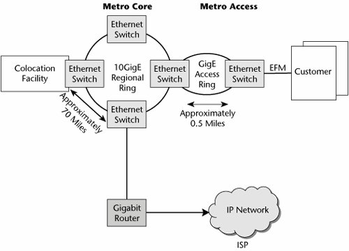
As discussed in the following sections, three standards from the IEEE aim to provide the core technology for the new data-centric public network of the peer-to-peer model (see Figure 11.14):
- 10GigE 10GigE, IEEE standard 802.3ae, supports 10Gbps and is targeted at the metro core and wide area networking. Along with operating at high speeds, 10GigE networks can unite LANs and WANs under a single technology.
- Ethernet First Mile (EFM) EFM, specified under IEEE standard 802.3ah, supports 1Gbps and is targeted at the first (or last) mile.
- Resilient Packet Ring and other new standards Resilient Packet Ring, specified by the IEEE 802.17 working group, is a standard for the optimized transport of data traffic over fiber rings. Its purpose is to provide the same resilience that SDH/SONET networks offer (50-millisecond restoration), but by using packet-based transmission rather than circuit-switched connections. The main goal is to increase the efficiency of IP services and Ethernet.
Figure 11.14. The Ethernet metro network
10GigE
Today, 10GigE, which is in the early stages of deployment, is the highest-bandwidth Ethernet offering. Some of the main 10GigE applications include colocation of carrier facilities, inter-POP connectivity, storage area network (SAN) connectivity, data center disaster recovery and mirroring systems, multimedia transport, computer-aided design, medical file transport, data center access, and local loop access. Therefore, the most likely environments for 10GigE are carriers, university campuses, research and development labs, and some government agencies. But, at the moment, 10GigE is not a common enterprise solution, although it may become so in the near term as companies seek more bandwidth to accommodate advanced applications while wishing to use a technology with which they have well-founded knowledge and experience.
The IEEE is setting two separate physical-layer standards for 10GigE. The first is for LANs; it offers a capacity of exactly 10Gbps and is really just a faster version of GigE. The second is targeted at WANs. Strictly speaking, it is not Ethernet, and it does not run at 10Gbps; instead, it transports Ethernet frames over an SDH or SONET link at 9.29Gbps, which makes is compatible with existing carrier networks but limits the number of GigE links that can be aggregated to nine.
There are two categories of WAN physical interfaces for 10GigE: electrical and optical. Electrical interfaces are less costly to build than optical interfaces, and the reality is that today most commercial buildings do not have fiber access. There are two electrical interfaces. 10Gbps on coax, known as 10GBASE-CX4, has about a 50-foot (15-m) range. It would most likely be used to connect devices within the same room. The other interface is 10Gbps on wire pair, using unshielded twisted-pair. Real solutions are expected sometime in 2006, with the initial definitions including 10GBASE-T over Category 7 wiring (up to 330-foot [100-m] range), screened or enhanced Category 6 wiring (up to 330-foot [100-m] range), or standard Category 6 (less than or equal to 180 feet [55 m]).
In terms of fiber options, a LAN physical interface can operate at the full 10Gbps rate up to a range of 1,000 feet (300 m). This would be suitable for local applications and could be configured to run either point-to-point links or over Resilient Packet Ring. WAN physical interfaces are designed for WANs and pack the Ethernet frames into an SDH/STM 64C payload (OC-192, or 10Gbps), providing a usable capacity of 9.29Gbps. Table 11.1 compares the various physical interfaces for 10GigE.
|
Characteristic |
LAN Physical Layer |
LAN Physical Layer |
WAN Physical Layer |
|---|---|---|---|
|
Interface |
Serial |
4-Lane LAN/WWDM[*] |
Serial |
|
Usable data rate |
10Gbps |
10Gbps |
9.29Gbps |
|
Physical media wavelength/range |
1,550 nm/ 1,310 nm/ 850 nm/ |
1,275.2 nm, 1,300.2 nm, 1,324.7 nm, 1,349.2 nm For multimode fiber, range |
1,550 nm/ 1,310 nm/ 850 nm/ |
|
Line rate |
10.3Gbps |
4 x 3.125Gbps |
9.953Gbps |
 65 m
65 m[*] WWDM (Wide WDM) refers to CWDM operating at 1,310 nm, compared to traditional CWDM, which operates at 850 nm.
EFM
EFM, standard 802.3ah, addresses Layer 1 enhancements for metro and wide area Ethernet services, such as providing for an extended range. EFM allows for operation on copper wire and includes Layer 1 testing capabilities.
Three main physical options for EFM are being developed:
- EFM fiber As the name implies, this option is geared toward supporting Ethernet access over point-to-point fiber-optic facilities. Although there are currently a number of point-to-point fiber options available for Ethernet, they need enhancements in the areas of operations, administration, and maintenance.
- EFM PONs In the context of the EFM standards, PONs provide for point-to-multipoint shared fiber access. (PONs in general are discussed in more detail earlier in this chapter and in Chapter 12.)
- EFM copper This option supports point-to-point facilities over copper wire using DSL technology. This is an interesting option, given the huge amount of installed copper wire. This option mandates operation on telco unshielded twisted-pair, not LAN cable, and there are minimum performance goals. On a short reach, the goal is 10Mbps up to 0.5 miles (750 m); on a long reach, it is 2Mbps up to 1.67 miles (2.7 km).
The EFM standards also address two modem options: Discrete Multitone (DMT), which is currently used in most DSL modems, and Quadrature Amplitude Modulation (QAM), which is used in HDSL and VDSL modems.
Finally, the EFM committee is also concerned with inverse multiplexing, one application of which is the use of multiple transmission paths to create a high-bandwidth channel (referred to as bonding). ADSL2 defines an ATM-based inverse multiplexing scheme, but in general, the EFM committee favors an Ethernet-oriented approach.
Resilient Packet Ring and Other New Standards Initiatives
Several major standards initiatives are under way to address the resiliency and QoS issues of Ethernet. The IEEE 802.17 working group is defining the Resilient Packet Ring access protocol for use in LANs, MANs, and WANs, for transfer of data packets at rates scalable to many gigabits per second. Resilient Packet Ring technology enables high-speed, survivable ring networks that are optimized for IP and other packet data. This new standard will use existing physical-layer specifications and will develop new interfaces, where appropriate.
Major features of Resilient Packet Ring include a dual-counter-rotating ring format, automatic discovery for adding new stations, a fairness principle that replaces the contention-based Ethernet CSMA protocol with a priority-based access protocol, destination stripping or spatial reuse, and protection whereby Resilient Packet Ring can be restored in 50 milliseconds or less. In addition, Resilient Packet Ring can carry voice and data traffic, which means it is possible to define jitter-free services with low latency for voice and video.
As mentioned earlier, Resilient Packet Ring aims to increase the efficiency of Ethernet and IP services, providing the resilience found in SDH/SONET networks as a function of their network restoration capabilities, and in this way optimizing the transport of data traffic over fiber rings. Resilient Packet Ring also employs the SDH/SONET concept of dual-counter-rotating rings, but in the case of Resilient Packet Ring, they are called ringlets. Ringlets connect Resilient Packet Ring stations at nodes where ingress and egress data traffic is dropped. MAC messages are used to direct the traffic in both directions around the ringlet. Bandwidth negotiation between the nodes is done by using a fairness algorithm. Furthermore, all the traffic on a given ringlet is assigned a class of service, with the standard specifying three classes: Class A (high) traffic exists to support low-latency and low-jitter applications, such as voice and video, requiring a pure committed information rate (CIR); Class B (medium) traffic combines CIR and excess information rate (EIR) metrics, introducing queuing based on fairness; and Class C (low) traffic, used for basic Internet access, covers best-effort traffic, providing whatever bandwidth may be available.
An important feature of Resilient Packet Ring is spatial reuse: Resilient Packet Ring removes the signal off the ringlet when it reaches the destination, allowing the freed space to carry additional traffic. (SHD/SONET, by comparison, uses the bandwidth around the entire ring.)
The Overlay and Peer-to-Peer Models Compared
The OTN represents a new generation of physical framework, and it will therefore undoubtedly replace the existing PDH and SDH/SONET infrastructures, supporting WDM, greater bandwidth, and instant provisioning. GigE and 10GigE, offering the benefits of both low cost and familiar protocol solutions, will be favored by those seeking economical and rapid deployments. Both models have the support of strong communities, and we are therefore likely to see evidence of both going forward. We need to be able to control these networks, and that's the realm of the IP+optical control plane, which is the subject of the following section.
The IP+Optical Control Plane |
Part I: Communications Fundamentals
Telecommunications Technology Fundamentals
- Telecommunications Technology Fundamentals
- Transmission Lines
- Types of Network Connections
- The Electromagnetic Spectrum and Bandwidth
- Analog and Digital Transmission
- Multiplexing
- Political and Regulatory Forces in Telecommunications
Traditional Transmission Media
Establishing Communications Channels
- Establishing Communications Channels
- Establishing Connections: Networking Modes and Switching Modes
- The PSTN Versus the Internet
The PSTN
- The PSTN
- The PSTN Infrastructure
- The Transport Network Infrastructure
- Signaling Systems
- Intelligent Networks
- SS7 and Next-Generation Networks
Part II: Data Networking and the Internet
Data Communications Basics
- Data Communications Basics
- The Evolution of Data Communications
- Data Flow
- The OSI Reference Model and the TCP/IP Reference Model
Local Area Networking
Wide Area Networking
The Internet and IP Infrastructures
- The Internet and IP Infrastructures
- Internet Basics
- Internet Addressing and Address Resolution
- The Organization of the Internet
- IP QoS
- Whats Next on the Internet
Part III: The New Generation of Networks
IP Services
Next-Generation Networks
- Next-Generation Networks
- The Broadband Evolution
- Multimedia Networking Requirements
- The Broadband Infrastructure
- Next-Generation Networks and Convergence
- The Next-Generation Network Infrastructure
Optical Networking
- Optical Networking
- Optical Networking Today and Tomorrow
- End-to-End Optical Networking
- The Optical Edge
- The Optical Core: Overlay Versus Peer-to-Peer Networking Models
- The IP+Optical Control Plane
- The Migration to Optical Networking
Broadband Access Alternatives
- Broadband Access Alternatives
- Drivers of Broadband Access
- DSL Technology
- Cable TV Networks
- Fiber Solutions
- Wireless Broadband
- Broadband PLT
- HANs
Part IV: Wireless Communications
Wireless Communications Basics
- Wireless Communications Basics
- A Brief History of Wireless Telecommunications
- Wireless Communications Regulations Issues
- Wireless Impairments
- Antennas
- Wireless Bandwidth
- Wireless Signal Modulation
- Spectrum Utilization
Wireless WANs
- Wireless WANs
- 1G: Analog Transmission
- 2G: Digital Cellular Radio
- 5G: Enhanced Data Services
- 3G: Moving Toward Broadband Wireless
- Beyond 3G
- 4G: Wireless Broadband
- 5G: Intelligent Technologies
WMANs, WLANs, and WPANs
Emerging Wireless Applications
- Emerging Wireless Applications
- The Handset Revolution
- Mobile IP
- The IP Multimedia Subsystem
- Mobile Gaming
- Mobile Video
- Mobile TV
- Mobile Content
Glossary
EAN: 2147483647
Pages: 160
- Challenging the Unpredictable: Changeable Order Management Systems
- Enterprise Application Integration: New Solutions for a Solved Problem or a Challenging Research Field?
- Data Mining for Business Process Reengineering
- A Hybrid Clustering Technique to Improve Patient Data Quality
- Relevance and Micro-Relevance for the Professional as Determinants of IT-Diffusion and IT-Use in Healthcare
