Circuit-Switched Networks
There are two main types of circuit-switched WANs: those based on leased lines and customer premises equipment (CPE) to manage the leased lines and those based on ISDN, including both Basic Rate Interface (BRI) and Primary Rate Interface (PRI).
Networks Based on Leased Lines
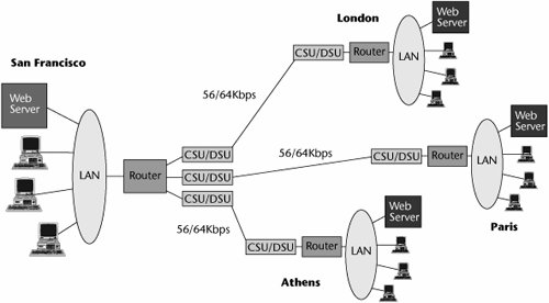
Leased lines can be configured in two different ways. The first approach uses point-to-point leased lines, as shown in Figure 7.2. In this approach, a communications link joins two nodesand only two nodes. The good thing about this setup, of course, is that there is no contention. The two devices always have an available communications path. The disadvantage becomes pronounced when the network starts to grow, either in the number of devices or in the distance between the locations. Because leased lines are calculated on a mileage-sensitive basis, the cost increases as the network scope increases.
Figure 7.2. A point-to-point leased-line network
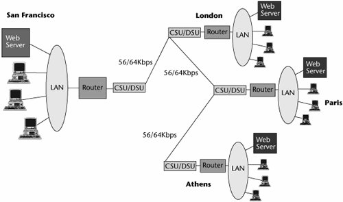
To increase the cost-efficiency of a leased-line network, you can use the second approach: a multipoint leased-line network. A multipoint leased-line network has a shared communications facility, and multiple nodes vie for access to the communications link. The advantage of this configuration is that it combines mileage, so the overall monthly cost associated with the leased line is reduced. The disadvantage is that it requires some type of intelligent scheme that helps determine which device gets to use the communications pathway at what time. Figure 7.3 shows a multipoint leased-line network.
Figure 7.3. A multipoint leased-line network
Leased lines can be configured on a point-to-point or multipoint basis by using a number of approaches, including these:
- DDSs, which essentially use 56Kbps or 64Kbps leased lines
- T-, E-, or J-carrier backbone
- SDH/SONET backbone
- Dark fiber backbone
The following sections describe these approaches.
DDSs
A DDS uses leased lines that operate at either 56Kbps or 64Kbps, depending on whether the network uses T-, E-, or J-carrier infrastructure. Figure 7.4 illustrates the equipment associated with a DDS network. Two pieces of equipment are located at the customer site: the DTE (e.g., host computers, routers) and DCE (e.g., the data service unit [DSU]), which are connected to one another via a physical interface (e.g., an RS-232, a V.35). The data access line (i.e., the 56Kbps or 64Kbps facility) runs from the DCE to a specialized DDS hub that is a digital circuit switch. (When this service was introduced, local exchanges were analog, so in order to introduce DDS into a metropolitan area, the telcos had to put into the exchange environment a specific digital circuit-switched hub for those services.) The DDS hubs connect into the digital transport network; destination cities attach to the network the same way, using the same equipment configurations.
Figure 7.4. DDS equipment
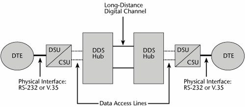
A DSU is a device that connects various DTE via RS-232 or V.35 interfaces with the digital services that offer 56Kbps or 64Kbps access. DSUs can be used to accommodate DDS, Frame Relay, and ATM facilities. When a DSU is combined with a channel service unit (CSU), it interfaces with services at the 64Kbps level, as well as n x 64Kbps, up to either T-1, E-1, or J-1 capacities. (These levels are described in detail in Chapter 4, "The PSTN.") The DSU converts the binary data pulse it receives from the DTE to the line-encoding format required by the network. Within the computer, the one bits are positive voltages, and the zero bits are no voltages or low-level voltages. The ones density rule says that if more than 15 zeros in a row are transmitted, the network may lose synchronization, which means transmission errors could occur. Therefore, the DSU performs a bipolar variationit alternates the one bits as positive and as negative voltages. The DSU also supplies the transmit and receive logic, as well as the timing. The CSU provides a means to perform diagnostics.
DDS facilities can be used for LAN interconnection, access to the Internet, and remote PC access to local hosts. One thing to bear in mind with a traditional DDS approach is that it is a leased-line service. If the leased line goes down, the network is out of service, and recovering the service can be a lengthy process, depending on how many network providers are associated with the link end to end. The mere process of troubleshooting and identifying within whose network the problem lies can often lead to resolution times of 24 to 48 hoursor even more, if network managers do not cooperate with one another. If you rely on a DDS network for critical applications, you need a backup in case the leased line fails at some point, and the best backup option is generally switched digital access, a dialup option in which facilities are allocated based on demand rather than associated with a specific customer all the time. Switched digital access supports transmission rates of 56Kbps, 64Kbps, 384Kbps, and 1,536Kbps. Another potential backup is ISDN, which is described later in this chapter.
T-, E-, or J-Carrier Backbone
In the 1980s, as networks, traffic, and applications were evolving and growing, customers saw a rise in the amount of data traffic they were carrying, and they began to institute various data services in response. This resulted in a hodgepodge of single-purpose networks based on leased lines that included unique universes of equipment or specific applications.
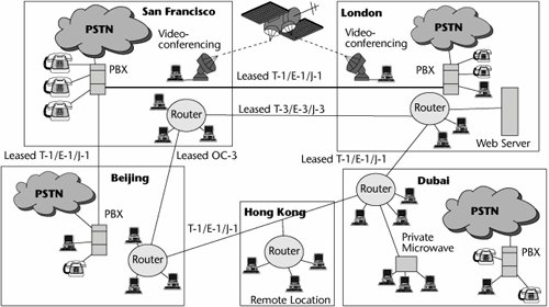
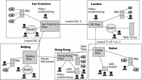
For example, assume that your company owns the networks shown in Figure 7.5. Both point-to-point and multipoint leased lines are being used to provide connectivity between LANs in various cities around the world. The PBXs for the most part rely on the PSTN, but there is a leased line between San Francisco and London because of the volume of traffic and security requirements. The videoconferencing systems between San Francisco and London use a specially provisioned satellite link. In essence, there are four separate networks, you're paying for four different infrastructures, and you don't have complete connectivity between all the locations, users, and resources. You therefore want to build an enterprise backbone network that ties together everybody with one common infrastructure and that provides for more fluid connectivity between the various locations and applications. This requires intelligent equipment at each location, to manage the transmission resource and to properly allocate the capacity to voice, data, image, video, fax, or other forms of transmissions.
Figure 7.5. Single-purpose leased-line networks
The facilities used to transport the information on this revised network can be combinations of privately owned and leased facilities, but you, the customer, own and are responsible for the equipment to manage those transmission facilities. You might be leasing a T-1 or an E-1 from a network operator, or you might be leasing dark fiber from a railroad company. Between some locations, you might deploy a privately owned digital microwave system. By whatever means you choose, you can integrate what used to be four separate networks into one cohesive backbone (see Figure 7.6). In terms of the capacities and components that would then be used within that backbone, the majority of customers today would rely on the dimensions deliverable from the T-, E-, and J-carrier infrastructure, although those with very large data centers and high levels of multimedia and visual applications have already migrated to the optical carrier levels of the SDH/SONET hierarchy.
Figure 7.6. An enterprise backbone network
A customer needs the following equipment to manage transmission facilities (refer to Figure 4.5 in Chapter 4):
- Transmission media The customer might be using copper twisted-pairs with T-1 or E-1 and might be using higher-bandwidth media such as coax, microwave, or fiber with T-3 or E-3 capacities. These are four-wire circuits operating in full-duplex, which means that you can communicate in both directions simultaneously.
- CSUs A CSU terminates each end of the T-1/E-1/J-1 carrier facility. A CSU equalizes the received signal, filters the transmitted and received waveforms, and interacts with the customer's and the carrier's test facilities so that diagnostics can be performed. Essentially, the CSU is used to set up the T-1/E-1/J-1 line with a customer-owned PBX, channel banks as standalone devices, intelligent multiplexers (e.g., T-, E-, or J-carrier multiplexers), and any other DS-x/CEPT-x-compliant DTE, such as digital cross-connects.
- Multiplexers A channel bank is a type of mux that consolidates the individual channels: 24 channels are associated with T-1, and 32 channels are associated with E-1. These voice and data channels are 64Kbps each, and they can be aggregated onto a higher-speed transmission line. Channel banks were designed to accept analog input, so if there is an analog switch either at the PBX or at the local exchange, that analog signal can be digitized, using Pulse Code Modulation (PCM), as described in Chapter 4. The channel banks provide a first level of aggregation. Beyond that, the customer might want to migrate to higher bandwidth, which would involve using T-1/E-1 or T-3/E-3 multiplexers. (Refer to Chapter 4 for a description of the rates associated with the various digital signal levels.)
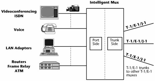
Intelligent multiplexers are the most important equipment in building the enterprise backbone network because they act dynamically to manage transmission resources. They allow you to make on-the-fly decisions about who is allocated the capacity, how much capacity needs to be allocated to each user, and whether individual users have rights to access the resource they want to access. In Figure 7.7, the intelligent muxes basically form a smart computer. An intelligent mux has a port side to which you interface the universe of information resources, which could be the videoconferencing systems, or the voice systems, or the variety of data universe that you have. On the trunk side, you terminate the T-1s/E-1s or T-3s/E-3s.
Figure 7.7. T-1/E-1 and T-3/E-3 muxes
Inside the muxes are databases that allow you to make decisions in real-time. One of the greatest benefits of managing your own bandwidth between locations is that you can use that bandwidth as you need it. There are two ways you can use T-, E-, or J-carrier facilities. First, you can use them as an access pipe. For example, you can use a T-1 to access the local exchange and to replace combined voice and data trunks. When you are using it to access the PSTN, you have to work within the subscribed standards. For example, with T-1 you get 24 channels at 64Kbps per channel, so if you have only a little bit of data to send, you can't reallocate your extra bandwidth to another application. You are stuck with static bandwidth allocation (see Figure 7.8), either 24 64Kbps channels or 1 1,536Kbps channel.
Figure 7.8. Static versus dynamic bandwidth allocation
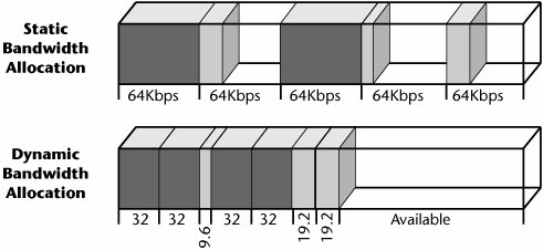
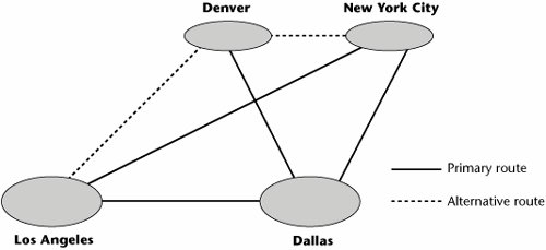
A second way in which you can use T-, E-, or J-carrier facilities is to build a private network. For example, if you use a T-1/E-1 to tie together two of your own locations, you can basically do as you wish with that pipe. You're in control of it, and you have the intelligent equipment at either end that can manage it on your behalf. For example, you can dynamically assign bandwidth; you can allocate only as much capacity as is necessary for an application, which more efficiently uses the capacity available on the digital facility. When you use a T-1/E-1 to build a private network, you can also perform dynamic alternative routing. For example, in Figure 7.9, the primary route between Los Angeles and New York City is the direct diagonal line between them. But say there is a problem and that link fails. The multiplexer in Los Angeles will be smart enough to know to reroute its highest-priority traffic through Denver to get it to New York. And in Denver, it may reduce the second-priority traffic to third priority in order to make room for the incoming high-priority traffic from Los Angeles. When the primary link is recovered, the network will revert to the original routing mechanisms. Dynamic alternative routing is useful in the face of congestion, failure, and a customer's need to reconfigure capacities based on activities and personnel at given locations at random times.
Figure 7.9. Dynamic alternative routing
Another element that a customer can use in creating a comprehensive enterprise backbone is a digital cross-connect. This purpose of this device, introduced in 1985, was to automate the process of provisioning circuitsin essence, to replace the use of manual patch panels. The key feature of the digital cross-connect system (DCS) is its capability to "drop and insert," which means the cross-connect can exchange channels from one facility to another (refer to Figure 4.7 in Chapter 4). It is used to implement appropriate routing of traffic, to reroute around congestion or failure, or to allow customers to dynamically reconfigure their networks. With digital cross-connects, network configurations are defined entirely in software, which gives the customer great control and allows reconfigurations to be implemented in a matter of minutes rather than hours or days. The levels at which switching can be performed are at the DS-3/CEPT-3 level, DS-1/CEPT-1 level, and DS-0/CEPT-0 level. Sub-DS-0 and sub-CEPT-0 levels are also possible. This capability is also offered by some of the intelligent multiplexersthe T-1/E-1 and T-3/E-3 multiplexersso the functionality can be bundled.
The main applications for digital cross-connects are recovering after disasters, bypassing systems during scheduled maintenance, addressing peak traffic demand, and implementing temporary applications. For customers who need to support even more advanced applicationssuch as computer-aided design, three-dimensional modeling and simulation, visualization, and multimediathe capacities of the T-, E-, and J-carrier infrastructure may not suffice. The next step is to migrate to the SDH/SONET signal hierarchy.
SDH/SONET Backbone
As discussed in Chapter 4, SDH/SONET is the second generation of digital infrastructure, based on the use of fiber optics. With SDH/SONET, an enterprise today might subscribe to OC-1 (51Mbps) and OC-3 (155Mbps) in order to build an enterprise backbone. Service providers, like ISPs, often use the OC-12 (622Mbps) and OC-48 (2.5Gbps) levels, while the largest of carriers rely on OC-192 (10Gbps) backbones. In today's environment, given the high cost of such leased lines, the customers that use the SDH/SONET levels include airports, aerospace companies, universities that have medical campuses or significant art schools, entertainment companies, large government agencies such as the U.S. Internal Revenue Service, and the military. These organizations typically have a greater use of multimedia and visualization applications, requiring this type of bandwidth.
To build a private SDH/SONET network, a customer would need two types of multiplexers: terminal muxes and add/drop muxes (ADMs). A customer would also need two types of cross-connects to build such a network: wideband cross-connects and broadband cross-connects. (Chapter 4 describes these muxes and cross-connects.)
Dark Fiber
With dark fiber, the customer leases the fiber itself and buys the necessary equipment to actually activate the fiber. The customer pays for the physical media, not for bandwidth, and as the customer adds equipment that can either pulse more bits per second or extract more wavelengths out of the underlying fiber, the bandwidth essentially becomes cheaper and cheaper.
Networks Based on ISDN
Another circuit-switched WAN option is ISDN. The International Telecommunication Union Telecommunications Standardization sector (ITU-T) formalized the ISDN standard in 1983. According to the ITU-T (www.itu.org), ISDN is "a network evolved from the telephony integrated digital network that provides end-to-end connectivity to support a wide range of services, including voice and nonvoice services, to which users have access by a limited set or standard multipurpose customer interfaces."
One of the ideas behind Narrowband ISDN (N-ISDN), as the first generation of ISDN was called, was to give customers one access into the network, from which they could then engage in circuit-switched, leased-line, or packet-switched options. Although all these options were available before ISDN, each one generally required its own special access line and device, which meant extra costs and administrative responsibilities because of the large number of options. The goal of ISDN was to provide one plug into the network, from which you could then go out over multiple alternatives.
ISDN Networks
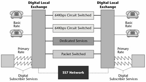
A couple key elements are required to form an ISDN network (see Figure 7.10). First, you must have a digital local exchange, and that digital exchange must be loaded with ISDN software. This is an expensive proposition. The ISDN software alone costs around US$1 million, and each exchange costs in the neighborhood of US$3 million to US$5 million. Along with a digital exchange and the proper ISDN software, you also need a Signaling System 7 (SS7) network and CPE that is compatible with the ISDN network. (SS7 is discussed in detail in Chapter 4.)
Figure 7.10. ISDN components
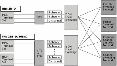
As discussed in Chapter 2, "Traditional Transmission Media," N-ISDN has two interfaces (see Figure 7.11):
- BRI BRI is primarily used for residential service, small businesses, and centrex environments. BRI is offered only by local telcos, and how they offer it varies greatly. It can be configured as either 1B, 2B, 1B+D, or the full 2B+D; 128Kbps transmission requires that two B-channels be used. One application for this is Internet access, so you might have a BRI device, such as an ISDN modem, that would bond two B-channels (and possibly the D-channel) to provide the 128Kbps (or 144Kbps) access to the ISP.
- PRI PRI is primarily used for business applications, and both local and interexchange carriers offer it. In support of the voice environment, PRI applications would include access to PBX and call center networks, replacement of existing analog trunk groups, and configuration of PBX tie-lines. Q-Sig, a standard that's an enhanced version of the D-channel signaling protocol, supports feature transparency between different vendors' PBXs. A key data application of PRI is LAN/WAN integration.
Figure 7.11. N-ISDN network interfaces
ISDN Applications
ISDN can be used in a number of different situations. The following are the main applications for N-ISDN:
- Internet access You could use N-ISDN to increase the speeds otherwise supported by your analog voice-grade line when you do not have other broadband access options, such as DSL, cable modems, or broadband wireless.
- Remote access You could use N-ISDN to give teleworkers or telecommuters access to corporate resources.
- LAN/WAN connections As mentioned earlier, N-ISDN is a technique for LAN interconnection, so you could bridge multiple LANs across a WAN over ISDN connections.
- High-capacity access You could use N-ISDN if you needed to increase your capacity for things such as graphics, file transfer, video, and multimedia networking. N-ISDN does not provide motion as good as what you would get with the higher-capacity services, but it is much better than what you get with an analog facility.
- Private-line backup You could use N-ISDN as a backup to the private-line services discussed earlier (e.g., DDS).
- Dialup Frame Relay access Frame Relay is a very popular data networking option, particularly for LAN-to-LAN interconnection. You could use ISDN to provide measured-use dialup access to Frame Relay services in which the user dials in to a remote access port on the carrier's Frame Relay switch at either 64Kbps or 128Kbps. You could do this at smaller sites and for remote access (e.g., for telecommuters).
- BRI 0B+D for packet data One 16Kbps D-channel can be shared by up to eight devices. BRI 0B+D makes use of 9.6Kbps of D-channel capacity to support low-speed data terminals. This requires a terminal adapter that encapsulates the user data in D-channel frames. Applications for BRI 0B+D include credit card terminals and automatic teller machines.
- ISDN DSL (IDSL) IDSL delivers full-duplex, dedicated data services; it does not support voice services. It is provided either on a 1B or a 2B configuration (i.e., 64Kbps or 128Kbps). IDSL is compatible with existing digital loop carrier systems, which serve 30% to 40% of the U.S. population. Digital loop carriers are especially common in remote rural areas. Some of the DSL services (which are discussed in Chapter 12, "Broadband Access Alternatives") are incompatible with these older-generation digital loop carriers. IDSL, however, is compatible with them, so it can be used to deliver digital private-line service at speeds up to 128Kbps. In today's environment, 128Kbps is definitely not a desired speed, so even though IDSL can facilitate some speedier communications than standard dialup, it is nowhere near what other broadband access options have to offer, making it an antiquated solution.
Part I: Communications Fundamentals
Telecommunications Technology Fundamentals
- Telecommunications Technology Fundamentals
- Transmission Lines
- Types of Network Connections
- The Electromagnetic Spectrum and Bandwidth
- Analog and Digital Transmission
- Multiplexing
- Political and Regulatory Forces in Telecommunications
Traditional Transmission Media
Establishing Communications Channels
- Establishing Communications Channels
- Establishing Connections: Networking Modes and Switching Modes
- The PSTN Versus the Internet
The PSTN
- The PSTN
- The PSTN Infrastructure
- The Transport Network Infrastructure
- Signaling Systems
- Intelligent Networks
- SS7 and Next-Generation Networks
Part II: Data Networking and the Internet
Data Communications Basics
- Data Communications Basics
- The Evolution of Data Communications
- Data Flow
- The OSI Reference Model and the TCP/IP Reference Model
Local Area Networking
Wide Area Networking
- Wide Area Networking
- Circuit-Switched Networks
- Packet-Switched Networks
The Internet and IP Infrastructures
- The Internet and IP Infrastructures
- Internet Basics
- Internet Addressing and Address Resolution
- The Organization of the Internet
- IP QoS
- Whats Next on the Internet
Part III: The New Generation of Networks
IP Services
Next-Generation Networks
- Next-Generation Networks
- The Broadband Evolution
- Multimedia Networking Requirements
- The Broadband Infrastructure
- Next-Generation Networks and Convergence
- The Next-Generation Network Infrastructure
Optical Networking
- Optical Networking
- Optical Networking Today and Tomorrow
- End-to-End Optical Networking
- The Optical Edge
- The Optical Core: Overlay Versus Peer-to-Peer Networking Models
- The IP+Optical Control Plane
- The Migration to Optical Networking
Broadband Access Alternatives
- Broadband Access Alternatives
- Drivers of Broadband Access
- DSL Technology
- Cable TV Networks
- Fiber Solutions
- Wireless Broadband
- Broadband PLT
- HANs
Part IV: Wireless Communications
Wireless Communications Basics
- Wireless Communications Basics
- A Brief History of Wireless Telecommunications
- Wireless Communications Regulations Issues
- Wireless Impairments
- Antennas
- Wireless Bandwidth
- Wireless Signal Modulation
- Spectrum Utilization
Wireless WANs
- Wireless WANs
- 1G: Analog Transmission
- 2G: Digital Cellular Radio
- 5G: Enhanced Data Services
- 3G: Moving Toward Broadband Wireless
- Beyond 3G
- 4G: Wireless Broadband
- 5G: Intelligent Technologies
WMANs, WLANs, and WPANs
Emerging Wireless Applications
- Emerging Wireless Applications
- The Handset Revolution
- Mobile IP
- The IP Multimedia Subsystem
- Mobile Gaming
- Mobile Video
- Mobile TV
- Mobile Content
Glossary
EAN: 2147483647
Pages: 160
