Packet-Switched Networks
Packet switching was developed as a solution for the communications implications of interactive processing; it was designed to support bursty data traffic, which stays connected for a long time but is associated with low data volumes. Packet switching involves the application of statistical multiplexing, whereby numerous conversations can make use of one common communications channel, which significantly increases transmission efficiency. (Chapter 1, "Telecommunications Technology Fundamentals," discusses statistical multiplexing in more detail.) However, sharing a communications link introduces latency. A key issue that we are currently addressing is how packet-switched networks can support latency- and loss-sensitive traffic such as real-time streams. As discussed in Chapter 8, "The Internet and IP Infrastructures," and Chapter 10, "Next-Generation Networks," quality of service (QoS) mechanisms are a major requirement, and that is where much of our attention is currently focused.
With packet switching, packets are routed through a series of intermediate nodes, often involving multiple networks; they are routed in a store-and-forward manner through a series of packet switches (i.e., routers) that ultimately lead to the destination. Information is divided into packets that include a destination address and a sequence number.
The secret to understanding the various packet formats is realizing where their strengths and weaknesses lie. They vary as to the number of bits they contain, how much control they give you over delays or losses, and the rules they use to address the highways and the destination points. (See the simple analogy between transportation and communications networks in the sidebar "A Transportation Analogy to Packet Switching" in Chapter 3, "Establishing Communications Channels.")
Remember from Chapter 3 that packet switching deals with containerized, labeled entities we generically call packets, which vary in size. Packets come from different sourcesfrom different users at one customer site or from different users at different customer sites. All these different packets are statistically multiplexed and sent to their destinations over virtual circuits. Also remember from Chapter 1 that a virtual circuit is a set of logical connections that create a pathway between two points; they are not a physical connection that you can trace end to end that belongs to just one conversation. A virtual circuit is therefore a shared communications link that is set up on demand based on negotiated communications parameters.
Because packet switching is a store-and-forward process of relaying through a series of intermediate nodes, latency and packet loss can considerably degrade real-time (i.e., time-sensitive) applications. In fact, the first generation of packet switching, X.25, dealt with data only. It could not handle voice or video. As discussed later in this chapter, newer generations can handle data because we have found ways to design the network to handle the requirements of voice and video applications.
In general, in the traditional mode, packet switching offered no QoS guarantees; QoS simply was not a design objective. It did, however, offer the knowledge that packets would usually make it to their destination because they could be rerouted around trouble points. But because they could be rerouted around trouble points, which might mean congestion points or failed points, there could be no guarantees about the latencies or losses that you would experience. Therefore, it is a relatively new concept to try to build in QoS as a metric in packet-switched networks. New packet networks can provision QoS by means of resource management and allocation techniques, such as RSVP-TE. (QoS techniques are discussed in more detail in Chapters 8 and 10.)
A packet-switched network is a data-centric environment, and instead of switching millions of physical circuits, as happens in the circuit-switched environment, the data-centric network switches packets, or switched virtual circuits. Circuit switching makes individual paths from the source to the destination, and in the case of the telephone network, millions of individual paths are created. Packet switching provides a dynamically determined route (hopefully a good route) for each packet presented to the network from the source to the destination. In Figure 7.12, multiple packets are statistically multiplexed as they come in through the packet switch, a routing table is consulted, an appropriate path is selected, and the packets are sent over the correct virtual circuit, leading to the next most logical stop in the network.
Figure 7.12. Packet switching

The capacity of the transmission facilities between the switches directly affects the performance of packet-switched networks; this is why many new-generation packet switchesIP routers and ATM switches, for instancenow come with high-speed interfaces, such as OC-48 (i.e., 2.5Gbps) interfaces. OC-48 interfaces on a switch could potentially eliminate the need for an entire layer of aggregation that we currently do according to the traditional model of 64Kbps channels. By eliminating that layer of aggregation, we can actually allow direct connection to an optical network by using DWDM at the full rate of the service and interface. (See Chapter 1, "Telecommunications Technology Fundamentals," and Chapter 11, "Optical Networking," for information on DWDM.) With data traffic growing all the time, transport networks will increasingly rely on data switches to manage and aggregate the traffic, and the transport network will be providing low-cost and reliable connections between these switches.
Remember from Chapter 3 that there are two main types of packet-switched networks: connection-oriented and connectionless networks. In a connection-oriented environment (such as X.25, Frame Relay, ATM, and VPNs that are based on Frame Relay or ATM networks), a call is set up end to end at the onset of the communication. Only one call request process that contains the source and destination address is necessary. That initial call request packet establishes a virtual circuit to the destination so that subsequent packets need only be read for the marking information that defines the virtual circuit to be taken. The intermediate nodes do not need to look at the addressing information in order to calculate a path for each packet independently. This reduces delay because routing decisions do not have to be made at the intermediate nodes. Where the error control is performed depends on the generation of the network. With X.25, error detection and correction was a necessary feature of the network because the links were almost all analog and had high error rates.
A provision of X.25 was to detect and correct for errors while they were in transport, hence improving data communications. But as networks became more digital and fiber based, noise became less of a problem; thus, the subsequent generations of packet switchingFrame Relay and ATM, for instancegive the endpoints the responsibility for error detection and correction. Not having to stop packets and investigate them in the throes of transmission greatly decreases the delays that would otherwise be encountered. Of course, today this is not so much a problem because there are fast processors and hardware to assist in this. In a connection-oriented environment, a virtual circuit defines the path end-to-end, and all packets follow the same path throughout the course of the session.
As discussed in Chapter 3, the connectionless environment (which includes X.25 networks, the public Internet, private IP-based backbones, and LANs) can be likened to the postal service, in which a message is relayed from point to point, with each relay getting one step closer to its ultimate destination. In a connectionless environment, each packet of a message is an independent unit that contains the source and destination address. Each packet is independently routed at each intermediate node it crosses. The more hops it goes through, the greater the accumulated delays, which greatly affects delay-sensitive applications, including any form of real-time voice, real-time audio, real-time video, video-on-demand, and streaming media. But connectionless environments can work around problems, which is why they were so strong in the early days, when there were frequent system failures and links that were too noisy to perform correctly. Connectionless packets could circumvent system failures or noisy conditions and still meet at the destination point with high integrity. The connectionless environment offered the flexibility of routing around problem areas, but at the risk of greater overhead associated with the overall transmission because addressing had to be included in each packet, and also at the risk of greater delays because each packet had to be independently routed.
X.25
In 1970 Tymnet introduced X.25, which was the first generation of packet switching. X.25 packet-switching networks evolved as an option for data communications and therefore did not compete directly with the telephony providers. The providers of such networks were put in a special category, called value-added network (VAN) providers.
The X.25 packet-switching technique emerged out of a need to address the bursty data flow associated with interactive processing which emerged in the late 1960s. Because bursty data implies long connect times but low data volumes, the key advantage of X.25 was that it provided a technique for many conversations, or data sessions, to share a communications channel.
Because of when X.25 was created, it was based on an analog network infrastructure. A big problem with analog networks is the accumulation of noise through the amplification points, which leads to the very high error rate associated with analog networks. One of the value-added services provided by X.25 networks was error control as a function within the network. Because packet switching is a store-and-forward technique, at every intermediate node at which an X.25 packet would be halted, the packet would undergo an error check. If everything in the packet was correct, the intermediate node would return an acknowledgment to the original transmitting node, requesting it to forward the next packet. If the packet the node received was not correct, the node would send a message requesting a retransmission. Thus, at any point in the routing and relaying of those packets, if noise contributed to errors, the errors could be resolved, which resulted in a much more accurate data flow.
Remember that what is beneficial or not beneficial about a particular network depends on the prevailing conditions, so in an analog infrastructure where noise was an issue, error control was a highly desirable feature. But performing that error control procedure on every packet, at every node, in addition to looking up the proper routing instructions at each intermediate node for the next point to which to relay the packet, increased the delays encountered end to end during transmission. Because X.25 packet-switching networks were for data only, it was not important to be able to tightly control delays or losses; the endpoints would resolve any such problems.
While X.25 networks are still found around the world, their use is in dramatic decline, and they are being replaced by newer technologies, including Frame Relay, ATM, and the much-favored IP. However, in many portions of the developing world, X.25 is still often the only available reliable service and is used mainly in legacy transaction systems. Another common application has been automated teller machines (ATMs), but as more and more of these banking kiosks today involve multimedia interfaces, many of them are moving to higher-speed connections.
Frame Relay
The second generation of packet switching, Frame Relay, was introduced in 1991. Frame Relay assumes that there's a digital infrastructure in place and that few errors will result from network transmission problems, such as noise or jitter. Therefore, the entire error detection and correction process has been removed from the Frame Relay network, and error control is done entirely in the endpoints. This means that traffic is not delayed by being stopped and checked, which translates to much faster throughput over Frame Relay networks than over X.25 networks.
The lack of error control in the network also means that it is possible to carry voice and video over a Frame Relay network. However, Frame Relay is not innately designed to do that. The packet sizes enabled under Frame Relay are largeup to 4,096 bytesand variable, which means that there could be a 100-byte packet going through a network node, with a 4,000-byte packet right behind it. When you have packets of varying sizes, you can't predict the delay in processing those packets through the network, and when you can't predict the delay, you can't properly address the latency requirements of real-time voice or video. Yet it is possible, in fact, to run voice and video over Frame Relay networks by tweaking the system in one of several ways. For example, we could provision separate links to carry the voice and the data traffic, and thus some excess data bursting wouldn't affect any real-time telephony, for instance, that is under way. We could prioritize traffic by application and in that way enable access to bandwidth, based on priority. In public Frame Relay networks, we often convert frames to equal-sized cells. At the core of the Frame Relay network is ATM because ATM currently offers the strongest suite of tools for traffic management. Thus, many networks, including IP backbones, the Internet, and Frame Relay, have ATM at their core. We can trick the system in order to get added utility out of Frame Relay networks, but keep in mind that when we do this, we lose a little bit of the cost-efficiencies we would otherwise have by running all our traffic in the same manner over the same link.
The types of links that connect the Frame Relay switching points operate at high speedsthey run the full range of the wide band of the PDH hierarchy. Where a Frame Relay network is running over a T-carrier infrastructure, the links can operate at 1.5Mbps to 45Mbps; for networks being served by E-carrier platforms, the links can operate at 2Mbps to 34Mbps.
The standards for Frame Relay come from the ITU-T, which defines Frame Relay as "a conversational communication service provided by a subnetwork for high-speed bursty data." This definition implies that Frame Relay has two-way capability (it is "conversational") and that it is not an end-to-end solution (it is a "subnetwork"). So we don't look for a Frame Relay device such as a Frame Relay telephone; instead, we look at Frame Relay to serve as the cloudthat is, the WAN solution that links computer networks distributed across a country or across the world. And "high-speed bursty data" suggests that Frame Relay's preliminary application is in support of data and, specifically, LAN-to-LAN internetworking.
Frame Relay Applications
One environment that might be a candidate for Frame Relay is a hub-and-spoke network, in which traffic from remote locations travels through a central site. This is similar to the airline system, in which key airports serve as main hubs; the largest of the 777s travel between the main hubs, and to get to a smaller city, you go through a hub to get on a smaller aircraft that then takes you to your destination. Frame Relay is also used to replace the use of expensive leased lines. Depending on the network topology, Frame Relay could potentially reduce costs up to 50% compared to using leased lines.
Frame Relay is also used to give a network some bandwidth flexibilitythat is, bandwidth-on-demand. Because the main application of Frame Relay is LAN internetworking, and because LANs produce highly unpredictable traffic flows, paying for a subscribed set of bandwidth whether or not you're using it may not be very cost-effective. Frame Relay provides the capability to burst above what you've committed to financially. (This is discussed in the next section "Frame Relay Networks.")
Frame Relay is also useful in a multiprotocol environment. Although IP seems to rule the world, it is not the only protocol in use. There are SNA networks in place, still making use of IBM's Synchronous Data Link Control (SDLC). The largest legacy networks today are some of the billing systems run by the world's telco operators. Frame Relay is used by more than 60,000 enterprises worldwide, and those that are highly focused on multimedia applications use ATM. Few customers use only one protocol. They have multiple protocols in their networks, and Frame Relay can handle them all because it simply encapsulates another protocol into a Frame Relay envelope and carries it through the networkit doesn't care what's inside the envelope.
Closed user groupswhere you want to know who has access in and out of the networkcan be achieved with Frame Relay, unlike with the public Internet, where you have no idea who's on there at any point in time. Frame Relay also allows you to predict the level of the network's performance, so it enables you to set metrics. This makes it an especially attractive solution if you are operating with countries where there are good carrier infrastructures.
Frame Relay Networks
Frame Relay is an interface specification that defines how information must be packaged in order for a Frame Relay network to act on it and deliver it to its destination. Therefore, it is not necessarily associated with a specific piece of equipment. The Frame Relay interface could reside on multiple platforms. In Figure 7.13, for example, the Frame Relay interface resides on the DTE, which is most likely a router but could also be a Frame Relay access device (FRAD), used to provide access for Voice over Frame Relay (VoFR). It could be a T-1 or an E-1 multiplexer with a Frame Relay interface. One of the things that is so valuable about Frame Relay is that it doesn't represent an investment in altogether new technology. You can use it to upgrade existing platforms, which can make a lot of economic sense. Frame Relay can be deployed on a wide range of platforms, and predominantly it is seen today on routers.
Figure 7.13. An example of a Frame Relay interface
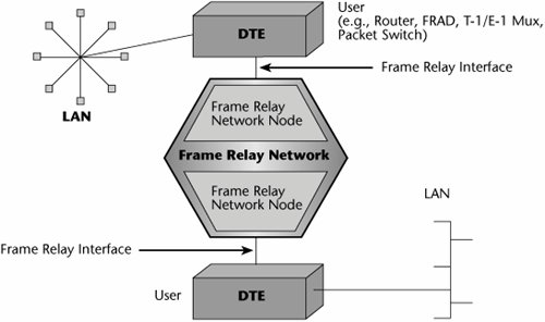
The Frame Relay interface takes the native data stream, no matter what the protocol (e.g., TCP/IP, SDLC, X.25), and puts it inside a Frame Relay envelope. Essentially, Frame Relay uses Link Access Protocol D (LAPD) to put the native data into an encapsulated form that the Frame Relay switches can act on.
Figure 7.14 shows the Frame Relay header format, LAPD. A beginning flag essentially starts the communication. A Frame Relay header is the very important part of the envelope that contains the addressing information. The user data is the native block of information. Next, the frame check sequence performs a cyclic redundancy check (CRC), and an ending flag closes the frame. An expanded view of the Frame Relay header includes the data link connection identifier (DLCI), which is a 10-bit field that represents the address of the frame and corresponds to a PVC. A few fields can be used for purposes of managing a minimal amount of QoS. The forward explicit congestion notification (FECN) and backward explicit congestion notification (BECN) fields are used to manage the traffic flow. The FECN tells the receiver, "I'm experiencing delays getting to you, so anticipate those delays. Don't time-out the session." FECN is rarely used. BECN tells the transmitter, "Whoa! We've got delays ahead. Throttle back or slow down on your introduction of data, or we'll end up losing those frames because of congestion." In other words, BECN indicates that all discard-eligible traffic is about to get dumped. You use the discard eligibility field to mark a frame as being either discard eligible or not and to control what occurs between voice and data in, for instance, a period of congestion. Frame Relay enables you to control the traffic flow a bit, and you can determine whether to drop a frame. But notice that there is no place in the frame for defining latency requirements or loss tolerancesthe stricter QoS traffic measurements. Nonetheless, the switches will read the DLCIs to determine how to properly forward the frame.
Figure 7.14. Frame Relay frame format (LAPD)

In a Frame Relay network, the customer environment includes the full complement of information resources that the customer wants to use on the network. Next, the CPEwhich could be a router, bridge, FRAD, mux, or switchcontains the interface that formats packets into the Frame Relay frames. From the CPE, an access line (called the User-to-Network Interface [UNI]) connects to the Frame Relay provider switch. That UNI could be a leased line, such as 56Kbps/64Kbps or T-1/E-1, an ISDN line, or an analog dialup line. The UNI then leads to the Frame Relay switch, which is basically a statistical multiplexer. Based on the type of subscription in place, the traffic is sent over either a permanent virtual circuit (PVC) or a switched virtual circuit (SVC). Recall from Chapter 1 that a PVC is analogous to a leased line. It is predetermined, and it is manually configured and entered into a network management system so that it stays between two locations until it is reprogrammed. SVCs, on the other hand, are like the dialup scenario; they are dynamically provisioned via signaling on an as-needed basis. (The reality is that PVCs are predominant, and SVCs are rare.)
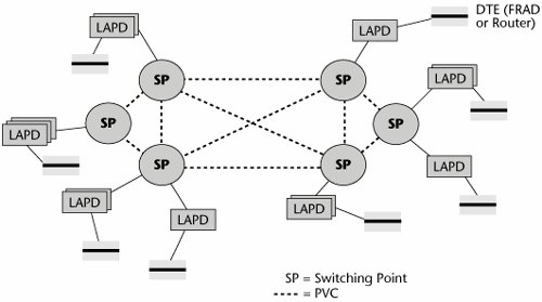
Figure 7.15 illustrates the use of PVCs. When a packet goes through the interface in the DTE (probably a router or a FRAD), it is put into the LAPD format, and then the LAPD frame is passed to the switching point. The switching point looks at the DLCI and then looks it up in its table to determine over which particular circuit or virtual circuit to send the message.
Figure 7.15. PVCs in a Frame Relay network
Subscribers specify the port speed and the committed information rate (CIR) in a Frame Relay network. Port prices are based on bandwidth, which determines the speed of the interface into the network. The PVC charges are based on the CIR and the distance. (The CIR generally refers to the PVC's minimum bandwidth under normal conditions. Generally, the CIR is less than the access rate into the network, and the access rate into the network determines the maximum amount of usable bandwidth.)
Figure 7.16 illustrates the concept of bandwidth-on-demand mentioned earlier in this chapter. Say you have an access line, an E-1, that allows 2.048Mbps to your carrier's switching point. Between these two locations of the network, you have contracted for a PVC that is essentially 1Mbps. In this environment, bandwidth-on-demand works like this: You are allowed to burst above your PVC's CIR of 1Mbps, up to the rate of your access line, or port speed, which is 2Mbps. In other words, you are paying for 1Mbps, but you're actually allowed to transmit at 2Mbps for short periods of time. However, note that the contracted-for 1Mbps has a discard eligibility of zero (DE = 0), ensuring that these frames do not get dropped. When you burst above your CIR, everything else is DE = 1, which means those frames could get dropped.
Figure 7.16. Frame Relay bandwidth-on-demand
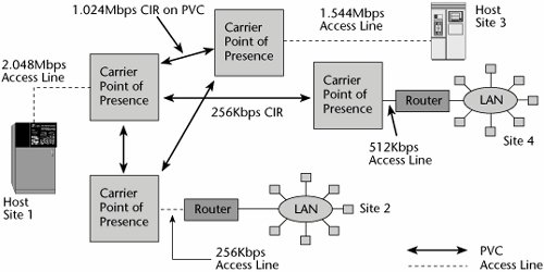
If you try to keep transmitting at your burst rate over a sustained period, the network will do one of two things. It might start dropping frames, which is another reason voice and video might suffer over Frame Relay. Or there might be a software mechanism that allows the excess traffic to be captured so that you can be billed for overtime. But the carrier is banking on the fact that not everybody is making use of the CIR at all times. Again, LAN traffic is quite unpredictable, so there are lulls in the day when you're not transmitting anything and other times when you need twice your CIR, and, ideally, at the end of the day it all balances out. But the carrier is playing the same gamble, assuming that not everybody is going to try to exercise their CIR at the same time. If they do, whether you still experience your CIR depends on the integrity of the Frame Relay provider's engineering. In other words, if the provider oversubscribes a PVC and if everyone attempts to burst at the same time, somebody is not going to have capacity available. This is a big issue in terms of vendor selection. Frame Relay networks are much less expensive than other options because the operators save on how they carry the traffic.
With SVCs, the connections are established on demand, so the routing tables do not store path identifiersjust the address of each site. Users can connect to any site, as long as the address is programmed into the router and SVC capacity is available. Subscribers control call setup via their own routers or FRADs. The router programming, then, controls allocation of the aggregate bandwidth. SVCs share bandwidth, and they do so either on a first-come, first-served basis or on a custom basis, where chosen SVCs are disconnected when a higher-priority application needs bandwidth.
Frame Relay Performance Issues
You need to consider a number of performance issues with Frame Relay:
- Likelihood of bottlenecks This depends on whether the operator has oversubscribed the backbone.
- Ability to handle bursts The operator may let you burst above your CIR for sufficient periods, or the bursts may be so limited that you really don't get bandwidth-on-demand.
- Level of network delay Operators commit to different maximum delays on different routes, so if you are going to be handling delay-sensitive traffic, you especially need to address this issue.
- Network availability guarantees You need to determine to what level you can get a service-level agreement (SLA) that guarantees network availability. This depends on the vendor, not on technology.
As far as Frame Relay QoS goes, you can expect to be able to have classes of service (CoSs), where you specify your CIR and your maximum burst rate, as well as some minor traffic parameters, such as the discard eligibility bits and the congestion notification bits. Otherwise, Frame Relay has no provisions for controlling latencies and losses.
VoFR
VoFR is of interest among both carriers and users. The main driver behind VoFR is more efficient use of Frame Relay bandwidth. The average full-duplex voice conversation consists of about half silence, so voice has a bursty quality. Data networks have been sharing bandwidth for many years. Voice is just another protocol, so why not let it also share bandwidth and in this way achieve better use of the Frame Relay resource? The goal of VoFR is not to replace existing voice networks but rather to make use of what is already available in Frame Relay to carry overflow traffic or additional voice traffic. Voice is compressed in Frame Relay and then encapsulated into the Frame Relay protocol via a FRAD. Again, the main advantage of this is better use of a single data network and the cost savings derived from this efficiency. But remember that if you run everything over a single network, voice quality may suffer, and, even worse, data performance may suffer.
The Frame Relay Forum has specified the FRF.11 standard for how to deploy VoFR. It provides bandwidth-efficient networking of digital voice and Group 3 fax communications over Frame Relay. It defines multiplexed virtual connections, up to 255 subchannels on a single Frame Relay DLCI, and it defines support of data subchannels on a multiplexed Frame Relay DLCI.
The ITU has defined some VoFR compression standards:
- ITU G.711 PCM Regular PCM is the compression standard that was part and parcel of the PDH hierarchy, which carried voice at 64Kbps. That's a very high rate, given what we can achieve today.
- ITU G.726/G.727 ADPCM Adaptive Differential PCM (ADPCM) compression reduces the data rate to 32Kbps, allowing for more efficient use of bandwidth.
- ITU G.723.1 MP-MLQ With Frame Relay networks, we can apply Multipulse Maximum Likelihood Quantization (MP-MLQ), which reduces voice to 4.8Kbps and can permit up to 10 voice channels on a single 64Kbps connection.
Another important feature of VoFR is voice activity detection (VAD). VAD algorithms reduce the amount of information needed to recreate the voice at the destination end by removing silent periods and redundant information found in human speech; this also helps with compression.
Another quality issue related to VoFR is jitter, the variation in delays on the receive side of the transmission from one packet to the next. Delay varies, depending on the traffic in the switch, and severe jitter can make conversations very difficult to understand. Dropped packets can cause clicks or pops, and a great deal of packet loss results in altogether unintelligible conversation.
FRF.12 addresses the fragmentation of both data frames and VoFR frames. It reduces delay variation, segments voice signals into smaller data bundles, and, ultimately, provides better performance. Because bundles are smaller, when some get lost, the network feels less impact.
Another VoFR consideration is the ability to prioritize voice traffic, which, of course, is very delay sensitive. The need for echo cancellation caused by round-trip delay is another consideration. Echo cancellation is required on voice circuits over 500 miles (800 km) long. A final consideration is voice interpolation. Equipment is needed to recreate lost voice information so that retransmissions don't need to be performed because voice retransmissions would be ineffective. Unlike data, voice cannot wait for retransmissions to occur.
Advantages and Disadvantages of Frame Relay
The advantages of Frame Relay are as follows:
- Provides cost savings compared to leased lines
- Runs on multiprotocol networks
- Provides control over the user community
- Gives predictable performance and reliability (although with congestion, performance can be, at best, uneven)
- Provides minimum guaranteed throughput
- Allows for network management and control
- Provides greater bandwidth flexibility
Disadvantages of Frame Relay include the following:
- Provides weak network management ability
- Is inherently unsuitable for delay-sensitive traffic, such as voice and video
- Requires high-quality digital circuits, so it does not work everywhere
- Is not entirely standardized
Overall, Frame Relay represents a viable and cost-effective solution for data networking, particularly where LAN-to-LAN interconnection is the main goal. However, recently, Frame Relay has begun to be displaced by ATM and IP. Also, the introduction of IP VPNs and dedicated broadband services such as DSL and cable modems may signal the end of Frame Relay's popularity. Nonetheless, there are still locations, such as rural areas, where DSL and cable modems are not available, and in those cases the Frame Relay alternative still presents the least costly approach to an always-on connection, allowing an enterprise with rural branches to connect those offices to the corporate WAN.
ATM
ATM is a series of standards that the ITU-T introduced in 1988 as part of a larger vision for the future of networks called Broadband ISDN. Broadband ISDN defined a new genre of applications, and most of those applications, not surprisingly, involved video or multimedia content, and this is where ATM shines. ATM was designed to be a master integrator: one platform, one infrastructure over which voice, data, video, multimedia, images, and other forms of traffic that we may have not thought of yet can all coexist and all be assigned the appropriate network resources based on their needs. ATM wasn't designed to be a technique for voice; it wasn't designed as a new solution for data. It was designed for multimedia, but it hasn't yet had a chance to really demonstrate its greatest strengths in today's environment.
A huge number of networksroughly 80% to 85% of all Internet backbones and Frame Relay networkshave ATM at their core. Today, ATM is still the only WAN approach that provides an architected QoS, which then gives network operators the opportunity to manage the traffic inside the network, which is a prerequisite to being able to offer business-class services, such as VPNs, VoFR, Voice over IP (VoIP), and Voice over ATM (VoATM). (However, it is important to note that today, MPLS, combined with RSVP-TE or CR-LDP, provides vastly improved QoS capabilities to the IP world, approaching that of ATM's structured architecture.) ATM has the capability to provide the appropriate guarantees to delay-sensitive traffic. ATM is working on your behalf more than may be evident in what you read and hear, especially as IP is the public's current darling. (Later in this chapter, the section "IP and ATM" discusses the possibility and benefits of marrying ATM and IP.)
By definition, ATM is a high-bandwidth, fast packet-switching and multiplexing technique that enables the seamless end-to-end transmission of voice, data, image, and video traffic. It's a high-capacity, low-latency switching fabric that's adaptable for multiservice and multirate connections. The capacities it affords, including low latency, are absolutely prerequisite to supporting the advanced applications for which this switching technology was designed.
ATM switches characteristically have large capacities. They range from 10Gbps to 160Gbps, and there are new products in the Tbps range. (In comparison, IP routers typically offer capacities ranging from 4Gbps to 60Gbps, although there are also new Tbps switch routers.)
The best advantages of ATM include the robust QoS and high-speed interfaces. ATM was the first networking approach to support high-speed interfaces, both 155Mbps and 622Mbps. Therefore, when an enterprise wanted to reengineer its campus network to higher bandwidth, ATM presented a viable solution. But the 1997 introduction of Gigabit Ethernet presented a more economical approach for obtaining high bandwidth, so today ATM is implemented in the enterprise because it offers the capability to administer QoS for multimedia and real-time traffic. Of course, over time, other solutions and architectures also begin to incorporate the features that people seek, so new-generation IP routers and switches accommodate the same high-speed interfaces that ATM does. Both ATM and IP today ship with 2.5Gbps (i.e., OC-48) interfaces. Today, ATM can administer QoS, and IP is getting close. (QoS and ATM's service classes are discussed in detail in Chapter 10.)
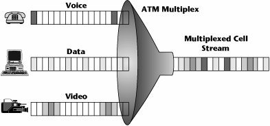
ATM enables access bandwidth to be shared among multiple sources, and it enables network resources to be shared among multiple users. It allows different services to be combined within a single access channel (see Figure 7.17).
Figure 7.17. Mapping services into ATM
ATM Applications
There are many key applications for ATM. The ATM standard began in the carrier community as a means of reengineering the PSTN to meet the demands of future applications. As Frame Relay networks began to see the demand to accommodate voice and video, they also began to institute ATM in their core in order to administrate service guarantees. The same goes for the Internet backbone, especially where there's an interest in providing more than just consumer Internet access but also business-class services, where the customer wants some SLAs tied to QoS and network performance.
There's also a need for ATM in VPNs that carry multimedia traffic, and you can also use it when you want to reengineer the network environment to be integratedfor example, replacing individual PBXs for voice and LAN switches for data with an enterprise network switch that can integrate all your traffic into one point at the customer edge.
Finally, ATM can be used to enhance or expand campus and workgroup networks; that is, it can be used to upgrade LANs. In the early days of ATM, one of the first marketplaces where it saw adoption was in the LAN community. If you wanted to make a move to a campus network that could support 155Mbps or 622Mbps, the only solution was to go to an ATM environment. However, Gigabit Ethernet is a much less expensive technology and transition path than ATM. To go from 100Mbps Ethernet to ATM means going to an entirely new technology. It's an investment in an entirely new generation of equipment, with a requirement for an entirely new set of technical skills. Many more applications developers are knowledgeable in other techniques, such as IP, than in ATM. However, Gigabit Ethernet doesn't require learning a new protocol, which is a benefit for network engineers. Gigabit Ethernet also has a much lower cost in terms of the actual components and boards. Therefore, with the formalization of Gigabit Ethernet, people turned away from using ATM in the LAN and decided they would simply throw bandwidth at the problem in the campus network. But remember that Ethernet does not within itself address QoS, so we can't continue to throw bandwidth at this problem much longer because when applications truly turn to the visual and multimedia realm, Gigabit Ethernet will not suffice, and QoS will need to be included. (But to be fair, this is an area of great debate, with many feeling that throwing cheap bandwidth at the problem will suffice.)
Organizations such as the U.S. Navy, universities, and health care campuses have deployed ATM, mainly due to the large amount of multimedia and visualization applications they use. ISPs are the biggest customers of ATM, followed by financial institutions, manufacturers, health care, government, education, research labs, and other enterprises that use broadband applications.
ATM drivers include the capability to consolidate multiple data, voice, and video applications onto a common transport network with specified QoS on a per-application basis. ATM is also being used to replace multiple point-to-point leased lines, which supported individual applications' networks. In addition, Frame Relay is being extended to speeds above T-1 and E-1.
The major inhibitor of ATM is the high service cost. Remember that one of the benefits of Frame Relay is that it is an upgrade of existing technology, so it doesn't require an entirely new set of skills and an investment in new equipment. ATM requires you to acquire an entirely new generation of equipment and build up skill sets to properly implement and manage ATM, and this may have a big financial impact on the overall picture. However, it is important to note that today IP networks are of most interest and are slowly but surely replacing existing deployments of both Frame Relay and ATM. (Given the importance of IP in the current environment, two chapters are dedicated to IP: Chapters 8 and 9.) As a result of these various problems, many vendors have dropped out of the market.
ATM Interfaces
ATM is a very high-bandwidth, high-performance system that uses a uniform 53-byte cell: 5 bytes of addressing information and 48 bytes of payload. The benefit of the small cell size is reduced latency in transmitting through the network nodes. The disadvantage of the small cell size is the increased overhead. But remember that ATM was built in support of the vision of Broadband ISDN, and the second set of standards in support of Broadband ISDN was SDH/SONET. This means that ATM was created with an eye toward the deployment of fiber, which offers tremendous capacities and hence makes bandwidth less of an issue.
An ATM network is connection oriented, which for purposes of real-time, multimedia, and time-sensitive traffic is very important because it allows controlled latencies. It operates over a virtual circuit path, which leads to great efficiency in terms of network management. Payload error control is done at the endpoints, and some limited error control procedures are performed on the headers of the cells within the network itself. ATM supports asynchronous information access: Some applications consume a high percentage of capacity (e.g., video-on-demand) and others consume much less (e.g., e-mail); thus, ATM allows multirate connections. Finally, ATM has a highly defined and structured set of QoS definitions, as discussed later in this chapter.
The ATM Layers
As discussed in the following sections, ATM has three main layers (see Figure 7.18): the physical layer, the ATM layer, and the ATM adaptation layer.
Figure 7.18. ATM layers

The Physical Layer
The physical layer basically defines what transmission media are supported, what transmission rates are supported, what physical interfaces are supported, and what the electrical and optical coding schemes are for the ones and zeros. Like the OSI model's physical layer, it's a definition of the physical elements of getting the ones and zeros over the network.
The ATM Layer
An ATM switch performs activities at the ATM layer. It performs four main functions: switching, routing, congestion management, and multiplexing.
The ATM Adaptation Layer
The ATM adaptation layer (AAL) is the segmentation and reassembly (SAR) layer. The native stream (whether it's real-time, analog, voice, MPEG-2 compressed video, or TCP/IP) goes through the adaptation layer, where it is segmented into 48-byte cells. Those 48-byte cells are then passed up to the first ATM switch in the network, which applies the header information that defines on which path and which channel the conversation is to take place. (This speaks, again, to the connection orientation of ATM.)
At the onset of the call, there is a negotiation phase, and each switch that's required to complete the call to the destination gets involved with determining whether it has a path and channel of the proper QoS to deliver on the requested call. If it does, at that time it makes a table entry that identifies what path and channel the call will take between the two switches. If along the way one of the switches can't guarantee the QoS being requested, the session is denied. ATM provides an end-to-end view of the network and an assurance that all along the way, the proper QoS can be met. Again, the AAL segments the information into 48-byte cells, and each switch, in turn, applies the headers that contain the routing information, and at the receiving end, the AAL again reassembles the cells into the native stream that is understood by the end device.
There are adaptation layers for various traffic typesfor real-time traffic, for connection-oriented data, for connectionless data, for compressed video, and so on:
- AAL 0 When a customer's network equipment takes care of all the AAL-related functions, the network uses a Null AAL (also known as AAL 0). This means that no services are performed and that cells are transferred transparently between the service interface and the ATM network.
- AAL 1 AAL 1 is designed to meet the needs of isochronous, constant-bit-rate (CBR) services, such as digital voice and video, and is used to support applications that are sensitive to both cell loss and delay and to emulate conventional leased lines. It requires an additional byte of header information for sequence numbering, leaving 47 bytes for payload. This adaptation layer corresponds to fractional and full T-1/E-1 and T-3/E-3. AAL 1 provides a timing recovery functional to maintain the bit timing across the ATM network and to avoid buffer overflow/underflow at the receiver.
- AAL 2 AAL 2 is for isochronous variable-bit-rate (VBR) services such as packetized video. It allows ATM cells to be transmitted before the payload is full to accommodate an application's timing requirements.
- AAL 3/4 AAL 3/4 supports VBR data, such as LAN applications, or bursty connection-oriented traffic, such as error messages. It is designed for traffic that can tolerate delay but not cell loss. This type performs error detection on each cell by using a sophisticated error-checking mechanism that consumes 4 bytes of each 48-byte payload. AAL 3/4 allows ATM cells to be multiplexed, and it supports the process of segmentation and reassembly required to carry variable-length frames over the ATM network. It also provides a per-cell CRC to detect transmission errors and a per-frame length check to detect loss of cells in a frame.
- AAL 5 AAL 5 is intended to accommodate bursty LAN data traffic with less overhead than AAL 3/4. It is also known as SEAL (simple and efficient adaptation layer). Its major feature is that it uses information in the cell header to identify the first and last cells of a frame, so it doesn't need to consume any of the cell payload to perform this function. AAL 5 uses a per-frame CRC to detect both transmission and cell-loss errors.
The speed- and traffic-shaping requirements of converged networks are increasingly challenging ATM, however. The fastest SARs known run at 2.5Gbps and have limited traffic-shaping capabilities, imposing performance bottlenecks at high speeds.
The ATM Transmission Path
The ATM transmission path includes two elements called the virtual path and the virtual channel (see Figure 7.19). You can think of the virtual channel as an individual conversation; each voice, video, data, and image transmission has its own unique virtual channel. The number of that channel will change between any two switches, depending on what was assigned at the time the session was negotiated.
Figure 7.19. The relationship of the virtual path, virtual channel, and transmission path
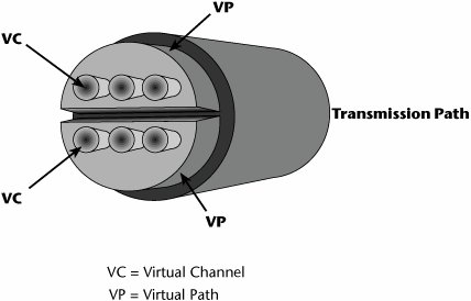
All similar virtual channelsthat is, all those that have the same QoS requestare bundled into a common virtual path. Virtual path 1 might be all real-time voice that has a very low tolerance for delay and loss; virtual path 2 might be for streaming media, which requires continuous bandwidth, minimum delay, and no loss; and virtual path 3 might be for non-mission-critical data, so best-effort service is fine. ATM is very elastic in terms of its tolerance of any losses and delays and allocation of bandwidth. It provides an easy means for the network operator to administrate QoS. Instead of having to manage each channel individually in order to guarantee the service class requested, the manager can do it on a path basis, thereby easing the network management process.
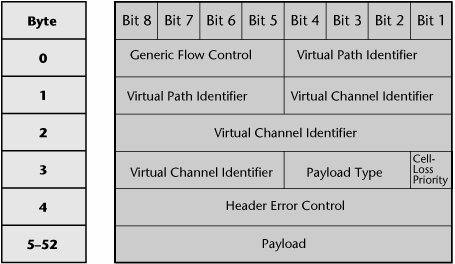
To illustrate how to identify what paths and channels need to be taken within the cell, Figure 7.20 shows the structure of an ATM cell. The header information includes information on the virtual path between switch A and switch B. It also shows the channel assignment, the type of payload, and the loss tolerance. In essence, the header provides the QoS metric, and the payload makes up the other 48 bytes of that cell. QoS is one of the great strengths of ATM, and ATM defines a series of specific QoS parameters that tailor cells to fit the video, data, voice, and mixed-media traffic.
Figure 7.20. ATM cell structure
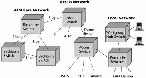
Where ATM Fits in the Network
As technologies evolve, they seem to find their first placement in the core network, where there are high traffic volumes, to justify the investments required for the new technologies. Therefore, much of today's ATM equipment is in core networksthose of ISPs, telcos, or other network operators. ATM then filters into the access network and into the metropolitan area network. Typically, you find it first where there are concentrations of early adoptertype customers. Ultimately, a new technology makes its way into the LAN, and it is then necessary to reengineer the local enterprise to provide QoS, not just high bandwidth (see Figure 7.21).
Figure 7.21. The ATM infrastructure
Advantages and Disadvantages of ATM
ATM's benefits can be summarized as follows:
- Provides hardware switching, which results in high performance
- Allows dynamic bandwidth for bursty data
- Provides CoS and QoS support for multimedia
- Scales in speed and network size
- Provides a common LAN/WAN architecture
- Provides opportunities for simplification via its virtual circuit architecture
- Has strong traffic-engineering and network management capabilities
The following are disadvantages of ATM:
- Has small cell size
- Has high overhead
- Has high service costs
- Requires new equipment
- Requires new technical expertise
Another disadvantage of ATM is that confusion arises when some of the capabilities of ATM begin to be offered by other approaches, such as Multiprotocol Label Switching (MPLS), as discussed in Chapter 10.
Current ATM Status
With the growing popularity of networks based on IP, ATM has a declining future. Nonetheless, the majority of telcos have implemented ATM in their WANs over the years, and most ADSL implementations use ATM. ATM is therefore not going away anytime soon. After all, significant investments were made, and still today, ATM offers the best way to ensure QoS and traffic management. The problem is that most vendors have dropped out of the ATM marketplace in favor of MPLS and other native IP solutions. ATM will continue to be used where it is deployed, in higher-speed interconnects, unifying PDH/SDH traffic and packet-switched traffic under a single infrastructure; in multiplexing services in support of DSL networks; and in carrying the majority of IP traffic. Interestingly, MPLS, the latest IP enhancement, borrows many of its technically sound ideas from ATM, enabling similar QoS capabilities without the cost and complexity of ATM. (MPLS is discussed in Chapter 10.)
Where ATM failed to gain widespread use was in the LAN environment, largely due to the emergence of Gigabit Ethernet, which provides high speeds at a much lower cost than ATM and without the complexity associated with ATM. Therefore, ATM did not realize its intended goal of being the single integrating network technology. As a result, most telcos are now planning to integrate voice and video traffic onto their IP networks, using MPLS to address the growing need for QoS to manage real-time traffic flows such as voice, video, and multimedia. Based on current trends, it is also likely that 10 Gigabit Ethernet will begin to replace ATM in many locations, enabling the convergence of voice, data, and video on one network, with one control plane. (The term control plane refers to infrastructure and distributed intelligence that sets up and releases connections and may restore a connection in case of a failure. It also includes protocols and mechanisms required to disseminate this information, as well as algorithms for engineering optimal paths between endpoints.)
IP and ATM
As discussed earlier in this section, ATM is used to support a great deal of Internet backbones. IP is also used in next-generation networks. (IP is discussed in detail in Chapter 8.) Approximately 85% of all IP backbones currently use ATM in the core, although MPLS is gradually being introduced in place of ATM.
Features of IP
IP was designed to work in the LAN world. It is a connectionless environment, which means it provides the capability of having information moved between network elements without a preconceived path between the source and destination. In a LAN environment, bandwidth is relatively inexpensive, and the deployment, by definition, is over a small geographic area. Because of the small coverage area, transit delay is typically not an issue in a LAN.
In the event of congestion, IP discards packets. TCP retransmits the lost packets quickly and transparently to the users, and because of the short transit delay, discarded packets are quickly detected, so users don't perceive delays in downloads. But WANs, by definition, are typically deployed over longer distances than LANs, and in WANs, transit delays become a major issue in two ways: in controlling the QoS and in identifying the loss of packets that may have occurred because of congestion. Also, bandwidth is more expensive in a WAN than in a LAN; you pay for every bit sent over a WAN link, so packet discards that create retransmissions can make the expense of retransmission alone significant.
Problems with IP Networks
Traditional IP routers were not intended to handle the large-scale type of networking that we are now demanding from IP. In IP router-based networks, the core, like the core in the PSTN, is responsible for providing interconnectivity. But in the IP router network, the core also provides server access and network management to the edge devices on the network periphery.
Because of the increased traffic that networks are seeing today, the core network is becoming loaded, and that is resulting in increased latency and unacceptable delays. At the edge of the LAN, a shortage of network capacity, coupled with proliferation of broadcasts and multicasts, can create significant network problems. However, those problems go away if the network is properly designed with VLANs that limit broadcast domains. When the edge demand exceeds the capacity of the core, queue overruns create capacity overload and lost packets, thereby reducing the availability and reliability of the network. As a result, users are suffering from congestion, inadequate server access, and slow response times.
Traditional IP routers cannot deliver the service quality that is increasingly demanded. The shortcomings of traditional routers include poor path calculation and slow rerouting. Routers usually use the shortest-path metric to calculate their routes, so IP routers send traffic over a shorter path, even if it's congested, instead of over a more desirable, longer, or uncongested path. But this depends on the routing protocol used. RIP uses the shortest-path metric, whereas OSPF, EIGRP, and BGP allow for load balancing and do not always take the shortest path but instead take the "best" path, as defined by the administrator. This is one of the reasons that there is increased use of ATM or MPLS in the core for backbone traffic-engineering purposes. Also, in the event of a backbone circuit or router failure, IP routers can take a long timeup to a minuteto calculate the new paths around the failure. This has led to more reliance on the resilient SDH/SONET backbone infrastructure, where there is a backup patha protect fiberwhich can ensure that the data is diverted to the protect fiber within a 50-millisecond time frame. SDH/SONET is now being replaced with WDM-based networks, but while early WDM systems did not provide for network restoration, the new generation of products do address this critical feature. (See Chapter 11 for discussion of optical networking technologies and trends.)
Recent introductions of VoIP services and streaming media have exposed two other limitations of IP networks: latency and jitter. IP doesn't provide a way to control latency and jitter. For a packet-based IP network to successfully support voice services, minimum transit delay must be achieved, and so must minimum packet loss. High-quality voice demands less than 100 milliseconds for total one-way latency, including all processing at both ends, which implies digitization, compression, decompression, queuing, playback, and so onand that must also include the network delay. Voice compression and decompression alone normally take about 30 to 50 milliseconds. Network latency must be tightly controlled to support these services properly.
One immediate solution to the problems of latency and jitter is to increase the amount of available bandwidth. If there's no congestion, there's no problem. And technologies such as DWDM provide relief initially, but history has taught us that the amount of data continues to increase significantly and rapidly, and while throwing bandwidth at the problem provides a quick fix, it does not address the growing need for detailed traffic and network management. Increasing bandwidth also does not provide the control mechanisms necessary for providing, tracking, and accounting for multiple and granular levels of service that the service provider can offer and guarantee for the customer. Therefore, simply providing more bandwidth is a short-term relief measure but not a long-term solution that addresses the need to differentiate traffic and its requirements on a very granular level. Hence the key to success for large-scale IP networking lies in delivering the flexibility of IP routing with a switched packet-forwarding mechanism that offers the highest possible performance and maximum control: IP switching.
IP Switching
IP switching was designed to speed up increasingly choked networks by replacing slower, more processing-intensive routers with switches. IP routers that provide connection-oriented services at the IP layer are referred to as IP switches. Routers are slower than switches because they must examine multiple packet fields, make substitutions in the packet headers, and compute routes on a packet-by-packet basis, which introduces latency and congestion.
The idea with IP switching is to make a connectionless data technology behave similar to a circuit-switched network. An IP switch routes the first packet, and then it switches all subsequent packets. The goal is to make intranet and Internet access faster and to enable the deployment of new voice, video, and graphics applications and services. Therefore, IP switching has two objectives: to provide a way for internetworks to scale economically and to provide effective QoS support for IP. In essence, IP switching replaces Layer 3 hops with Layer 2 switching, which leads to good hardware-based forwarding performance.
Even with the advantages of IP switching, IP still doesn't allow us to properly administer all the QoS parameters that are part of traffic definitions, and this is where ATM comes in.
Features of ATM
As discussed earlier in this chapter, ATM was created in the WAN environment. It came out of the carrier community as a means by which to reengineer the PSTN for multimedia and real-time streaming applications. Because ATM comes from the carrier environment, where traffic engineering is essential, it is a connection-oriented technique. It provides a means to establish a predefined path between the source and the destination, which enables greater control of network resources. Overallocation of bandwidth becomes an engineered decision; it offers a deterministic way to respond to changes, on a dynamic basis, to network status. A great benefit of ATM is that it provides for real-time traffic management. It enables policing and traffic shaping: It can monitor (i.e., police) the cells and determine, based on congestion, which cell should be dropped (i.e., perform traffic shaping).
ATM allows networkwide resource allocation for CoS and QoS provisioning. Again, because it is connection oriented, it looks ahead to the destination point to ensure that each link along the way can deliver on the requested QoS. If it can't, the session is denied. Therefore, ATM also makes possible deterministic transit delay because you can specify and calculate the end-to-end delays, as well as the variations in delays (jitter). This is all administered through multiple QoS levels.
Remember that a lot of IP takes place over ATM. Because it is connection oriented, ATM gives service providers the traffic-engineering tools they need to manage both QoS and utilization. ATM's virtual circuits control bandwidth allocation on busy backbone routes. In provisioning a network, the service provider can assign each virtual circuit a specific amount of bandwidth and a set of QoS parameters. The provider can then dictate what path each virtual circuit takes. Basing these decisions on overall traffic trends reduces the likelihood of network hot spots and wasted bandwidth, and this is why so many service providers turn to ATM to transport IP traffic. However, the service provider has to deal with two control planesmanaging both IP routers and ATM switches. Using ATM virtual circuits to interconnect IP routers leads to scaling problems because every router needs a separate virtual circuit to every other router. As the network grows, the number of routes and virtual circuits can increase exponentially, eventually exceeding the capacity of both switches and routers. Network operators can work around this in one of two ways: either they can forgo a full-mesh architecture or they can move to MPLS, which is discussed in Chapter 10.
IP Versus ATM
Table 7.1 is a simple overview comparison of IP and ATM.
|
Transport |
Benefit |
Drawback |
Services Supported |
Packet Size |
Header |
|---|---|---|---|---|---|
|
IP |
Pervasive at the desktop |
No QoS |
Data, voice |
Variable, 4064,000 bytes |
40 bytes |
|
ATM |
Multiple service classes |
Small cell size that is inefficient for data transport |
Data, voice, IP, Frame Relay, X.25, leased lines |
Fixed cells, 53 bytes |
5 bytes |
An upside of IP is that it is pervasive at the desktop. The downside is that it has no QoS built in. It supports data, voice, and fax. IP packet size is variable. It can be up to 64,000 bytes, but packets are segmented into 1,500-byte frames for transport, and 40 bytes of each packet is for the header information.
The upside of ATM is that it is an architected QoS approach that defines key service classes (as described in Chapter 10). The downside is that it uses a small cell size (only 53 bytes, 5 bytes of which is the header information), which means it has a lot of overhead (i.e., cell tax), which could be construed as inefficientfor data transport, for voice transport, or for other traffic typesand this is an issue when bandwidth is constrained and expensive. Remember that ATM was built based on the assumption of Gbps trunks and generous bandwidth, so the cell tax is less relevant if the prevailing condition is abundant bandwidth. ATM supports a wide variety of services, including voice, IP, Frame Relay, X.25, and leased lines.
We don't really have to choose between IP and ATM. At least for the time being, we can use them together quite effectively. IP has become the universal language of computer networking, especially in the desktop environment. IP-based servicesincluding VPNs, e-commerce, outsourced remote access, application hosting, multicasting, and VoIP, along with fax and video over IPare used in a number of areas. A benefit of IP is that there is a much larger pool of knowledgeable applications developers for IP than there is for ATM. However, all these wonderful applications that the programmers are developing for IP tend to require a lot of CoS and QoS, as well as controlled access. IP standards for QoS are not yet as effective as ATM's, and ATM therefore continues to be used to switch IP traffic because of its network management, restoration, and reliability capabilities.
Part I: Communications Fundamentals
Telecommunications Technology Fundamentals
- Telecommunications Technology Fundamentals
- Transmission Lines
- Types of Network Connections
- The Electromagnetic Spectrum and Bandwidth
- Analog and Digital Transmission
- Multiplexing
- Political and Regulatory Forces in Telecommunications
Traditional Transmission Media
Establishing Communications Channels
- Establishing Communications Channels
- Establishing Connections: Networking Modes and Switching Modes
- The PSTN Versus the Internet
The PSTN
- The PSTN
- The PSTN Infrastructure
- The Transport Network Infrastructure
- Signaling Systems
- Intelligent Networks
- SS7 and Next-Generation Networks
Part II: Data Networking and the Internet
Data Communications Basics
- Data Communications Basics
- The Evolution of Data Communications
- Data Flow
- The OSI Reference Model and the TCP/IP Reference Model
Local Area Networking
Wide Area Networking
- Wide Area Networking
- Circuit-Switched Networks
- Packet-Switched Networks
The Internet and IP Infrastructures
- The Internet and IP Infrastructures
- Internet Basics
- Internet Addressing and Address Resolution
- The Organization of the Internet
- IP QoS
- Whats Next on the Internet
Part III: The New Generation of Networks
IP Services
Next-Generation Networks
- Next-Generation Networks
- The Broadband Evolution
- Multimedia Networking Requirements
- The Broadband Infrastructure
- Next-Generation Networks and Convergence
- The Next-Generation Network Infrastructure
Optical Networking
- Optical Networking
- Optical Networking Today and Tomorrow
- End-to-End Optical Networking
- The Optical Edge
- The Optical Core: Overlay Versus Peer-to-Peer Networking Models
- The IP+Optical Control Plane
- The Migration to Optical Networking
Broadband Access Alternatives
- Broadband Access Alternatives
- Drivers of Broadband Access
- DSL Technology
- Cable TV Networks
- Fiber Solutions
- Wireless Broadband
- Broadband PLT
- HANs
Part IV: Wireless Communications
Wireless Communications Basics
- Wireless Communications Basics
- A Brief History of Wireless Telecommunications
- Wireless Communications Regulations Issues
- Wireless Impairments
- Antennas
- Wireless Bandwidth
- Wireless Signal Modulation
- Spectrum Utilization
Wireless WANs
- Wireless WANs
- 1G: Analog Transmission
- 2G: Digital Cellular Radio
- 5G: Enhanced Data Services
- 3G: Moving Toward Broadband Wireless
- Beyond 3G
- 4G: Wireless Broadband
- 5G: Intelligent Technologies
WMANs, WLANs, and WPANs
Emerging Wireless Applications
- Emerging Wireless Applications
- The Handset Revolution
- Mobile IP
- The IP Multimedia Subsystem
- Mobile Gaming
- Mobile Video
- Mobile TV
- Mobile Content
Glossary
EAN: 2147483647
Pages: 160
