OUTPUT REGISTERS-THE MULTI-ELEMENT TEXTURE (MET) AND THE MULTIPLE RENDER TARGET (MRT)
|
|
OUTPUT REGISTERS—THE MULTI-ELEMENT TEXTURE (MET) AND THE MULTIPLE RENDER TARGET (MRT)
| In DirectX 8 pixel shaders, only the r0 register was used to hold the output color. In DirectX 9 there is better support for specifying a texture as a render target: the Multiple Render Target (MRT) or a subset called the Multi-Element Texture (MET). This allows one to specify up to a four-dimensional texture (with an optional depth value) as output from a pixel shader. |
If you're not using a MRT/MET, the syntax is to use the oC0 register as the output color register. If your device supports multiple render targets, the output colors are sent to the appropriate render target. To use MRT/MET you'd use the four output color registers and output depth register. These registers are oC0 though oC3. The output registers must be written to in ascending order, and all elements of each register must be written to. Each register can only be written to once in a shader. If there's a depth buffer attached to the MRT surface, you can specify a depth value for the pixel in the oDepth register. This is a scalar register.
The restrictions on using an MRT as a destination are
-
The color elements can only be written with an .rgba mask.
-
You can write to an oCn or oDepth register only once per shader.
-
You must write to the oC0 register.
-
No_sat or source modifiers.
-
You cannot use an output mask when writing to oCn.
-
The range of oCn registers have to be updated sequentially. You're not allowed to skip outputs (i.e., you can't write oC0 and oC2, and not oC1).
The restrictions on using a MET as a destination are
-
All surfaces are allocated atomically.
-
Only 32-bit formats are supported.
-
MET surfaces have to be off-screen.
-
No fragment processing instructions.
-
MET surfaces can't be filtered when sampled from.
The restrictions on using oDepth are
-
You cannot specify a write mask when writing to oDepth.
-
You must specify a replicate swizzle when writing to oDepth.
| abs(macro) | ps 2.0 |
This macro computes the absolute value of the input register on an element-by-element basis.
One arithmetic instruction slot.
_______________________________________________________________________________ abs Dest0, Source0 _______________________________________________________________________________
| LEGAL REGISTER ARGUMENTS | |||||||||
|---|---|---|---|---|---|---|---|---|---|
| | |||||||||
| DESTINATION | SOURCE | ||||||||
| PS version | v | c | t | r | v | c | t | r | s |
| | |||||||||
| 1.0 | |||||||||
| 1.1 | |||||||||
| 1.2 | |||||||||
| 1.3 | |||||||||
| 1.4 phase 1 | |||||||||
| 1.2 phase 2 | |||||||||
| 2.0 | x | x | x | x | x | ||||
Computes the absolute value of each element of Source0 and places the result in Dest0.
abs r4, r4
This macro is equivalent to the following code:
_______________________________________________________________________________ cmp Dest0, Source0, Source0, -Source0 _______________________________________________________________________________
| add | ps 1.0–2.0 |
Adds two source colors and places the sum into a third register.
One arithmetic instruction slot.
_______________________________________________________________________________ add Dest0, Source0, Source1 _______________________________________________________________________________
| LEGAL REGISTER ARGUMENTS | ||||||||
|---|---|---|---|---|---|---|---|---|
| | ||||||||
| DESTINATION | SOURCE | |||||||
| PS version | v | c | t | r | v | c | t | r |
| | ||||||||
| 1.0 | x | x | x | x | x | |||
| 1.1 | x | x | x | x | x | x | ||
| 1.2 | x | x | x | x | x | x | ||
| 1.3 | x | x | x | x | x | x | ||
| 1.4 phase 1 | x | x | x | x | ||||
| 1.4 phase 2 | x | x | x | x | ||||
| 2.0 | x | x | x | x | x | |||
Adds the Source0 and Source1 registers and places the result in the Dest0 register.
add r0, r0, c2 add r0, r0, 1-r1 add r0, r0, t0_bias
| bem | ps 1.4 |
Bump-Environment-Map. Apply a fake bump environment map transform.
Two arithmetic instruction slots.
_______________________________________________________________________________ bem Dest0.rg, Source0, Source1 _______________________________________________________________________________
This instruction takes two source registers, applies the 2 2 bump map matrix to Source1, adds in Source0, and places the result in the destination register. This instruction operates only on the .rg components. The matrix values are set prior to the pixel shader through a SetTextureStage call setting the four D3DTSS_BUMPENVMATnn matrix elements. The destination register number determines the texture stage number. There are no restrictions on modifiers on the source registers. There are several restrictions on using the bem instruction.
-
Only one bem instruction can appear in a shader.
-
The bem instruction must be in phase one.
-
The source registers can be temporary or constant registers.
-
The destination must be a temporary register.
-
The destination mask must be .rg (or .xy).
-
The instruction cannot be co-issued.
| Note | This instruction works only in PS 1.4. In PS 2.0 you can use two dp2add instructions to emulate the bem instruction. |
bem r3.rg, r0, r0 // bump texture 3 * c2, add in r0 bem r4.xy c2, r0 // bump texture 4 * r0, add in c2
| LEGAL REGISTER ARGUMENTS | ||||||||||||
|---|---|---|---|---|---|---|---|---|---|---|---|---|
| | ||||||||||||
| DESTINATION | SOURCE | SOURCE1 | ||||||||||
| PS version | v | c | t | r | v | c | t | r | v | c | t | r |
| | ||||||||||||
| 1.0 | ||||||||||||
| 1.1 | ||||||||||||
| 1.2 | ||||||||||||
| 1.3 | ||||||||||||
| 1.4 phase 1 | x | x | x | x | ||||||||
| 1.4 phase 2 | ||||||||||||
| cmp | ps 1.2–1.4 |
Compare. Performs a conditional assignment based on a comparison of the values in the source registers.
Two arithmetic slots for PS 1.2 and 1.3; one for PS 1.4.
_______________________________________________________________________________ cmp Dest0, Source0, Source1, Source2 _______________________________________________________________________________
If the value in Source 0 is greater than or equal to zero, then Source1 is placed in the destination; otherwise, Source2 is placed in the destination. This comparison is performed on an element-by-element basis. Dest0 must be a different register from any of the source registers.
| Note | For PS 1.2 through 1.3, the source register can be any register, while the destination can be either a texture or a temporary register. There can be a maximum of three cmp instructions in a pixel shader. |
| Bug | For PS 1.2 and 1.3, the destination register cannot be the same as a source register, but validation fails to catch this. The cmp instruction takes up two slots, but validation counts this as only one slot. |
| For PS 1.4, the source register can be temporary registers, constant registers, or vertex color registers for phase two, whereas the source register can be temporary registers or constant registers for phase one. The destination register must be a temporary register. |
cmp r0, r1, c1, c2
| LEGAL REGISTER ARGUMENTS | ||||||||
|---|---|---|---|---|---|---|---|---|
| | ||||||||
| DESTINATION | SOURCE | |||||||
| PS version | v | c | t | r | v | c | t | r |
| | ||||||||
| 1.0 | ||||||||
| 1.1 | ||||||||
| 1.2 | x | x | x | x | x | x | ||
| 1.3 | x | x | x | x | x | x | ||
| 1.4 phase 1 | x | x | x | |||||
| 1.4 phase 2 | x | x | x | x | ||||
| cnd | ps 1.1–1.4 |
Conditional. Performs a conditional assignment based on a comparison of the value in r0.a (PS 1.1–1.3) or another register (PS1.4) with 0.5.
One arithmetic instruction slot.
_______________________________________________________________________________ cnd Dest0, Source0, Source1, Source2 _______________________________________________________________________________
Compares the value in r0.a to 0.5. Source0 must be r0.a for PS 1.1–1.3. If Source0 is greater than 0.5, then Dest0 is set to the value in Source1. If not, then Dest0 is set to the value in Source3.
| For PS 1.4, the cnd instruction operates on an element-by-element basis. |
| LEGAL REGISTER ARGUMENTS | ||||||||||||
|---|---|---|---|---|---|---|---|---|---|---|---|---|
| | ||||||||||||
| DESTINATION | SOURCE | SOURCE1/2 | ||||||||||
| PS version | v | c | t | r | v | c | t | r | v | c | t | r |
| | ||||||||||||
| 1.0 | ||||||||||||
| 1.1 | x | x | r0.a | x | x | x | x | |||||
| 1.2 | x | x | x | x | x | x | ||||||
| 1.3 | x | x | r0.a | x | x | x | x | |||||
| 1.4 phase 1 | x | x | x | x | x | |||||||
| 1.4 phase 2 | x | x | x | x | x | x | x | |||||
You can also use this command to compare two values with an added step as shown.
cnd r0, r0.a, c1, c2 // PS 1.1-PS 1.3 // to compare two values v0 and v1 sub r0, v0, v1_bias; r0 = v0 - (v1 - 0.5) = v0 - v1 + 0.5 cnd r0, r0.a, c0, c1; if r0.a > 0.5 use c0, else c1 ; thus v0-v1+0.5 > 0.5 = v0-v1 > 0 = v0 > v1
| crs (macro) | ps 2.0 |
The three component cross product.
Two arithmetic instruction slots.
_______________________________________________________________________________ crs Dest0, Source0, Source1 _______________________________________________________________________________
Computes the three component cross product using the right-hand rule. There cannot be ands swizzles on the source registers. Dest0 must have a write mask that is one of the following: .x, .y, .z, .xy, .xz, .yz, or .xyz. The destination register should be different from the source registers.
crs r1, v0, r0
This macro is equivalent to the following code sans write mask on Dest0.
_______________________________________________________________________________ mul Dest0, Source0.zxyw, Source1.yzxw mad Dest0, Source0.yzxw, Source1.zxyw, -Dest0 _______________________________________________________________________________
| LEGAL REGISTER ARGUMENTS | |||||||||
|---|---|---|---|---|---|---|---|---|---|
| | |||||||||
| DESTINATION | SOURCE | ||||||||
| PS version | v | c | t | r | v | c | t | r | s |
| | |||||||||
| 1.0 | |||||||||
| 1.1 | |||||||||
| 1.2 | |||||||||
| 1.3 | |||||||||
| 1.4 phase 1 | |||||||||
| 1.4 phase 2 | |||||||||
| 2.0 | x | x | x | x | x | ||||
| dcl | ps 2.0 |
Declare how a texture sampler register is to be used.
Takes no slots.
_______________________________________________________________________________ dc1_<type> Dest0 _______________________________________________________________________________
In order to make it easier to optimize and verify shaders, PS 2.0 now requires a declaration statement on all sampler, color input, and texture coordinate registers. All sampler registers must be declared before use in the shader. Dest0 will be a specific input register. The <type> tag is a texture register indicator of the type of texture this register is to be used with. The allowable types are; 2d, cube, and volume.
Color input and texture coordinate register must specify a mask of which components are used. Texture coordinate register may specify the partial precision (_pp) modifier.
Must appear before any arithmetic or texture instructions.
// sampler registers dcl_2d s1 // s1 will be using a 2D texture dcl_cube s2 // s2 will be using a cubemap dcl_volume s3 // s3 will be using a 3D texture // color and texture coordinate registers dcl t1.rg dcl_pp t2.rg dcl v0.rgba
| def | ps 1.0–2.0 |
Defines the constants to be used in the shader.
Takes no slot or time.
_______________________________________________________________________________ def Const1, float1, float2, float3, float4 _______________________________________________________________________________
The first argument is the name of the constant—c0, c1, etc. The remaining arguments are the four floating point values to be placed in the constant register in a, r, g, b order. The constants are available once the shader is loaded, but a subsequent call to SetPixelShaderConstant() will overwrite any constant values previously set except on PS 2.0, where the constants defined in the shader take precedence.
def c0, 0.Of, 0.0f, 0.0f, 0.0f def c1, 1.0, 0.5, 0.25, 0.125
| dp2add | ps 2.0 |
Two-component dot product plus a scalar add. Can be used to emulate the bem instruction.
One arithmetic instruction slot.
_______________________________________________________________________________ dp2add Dest0, Source0, Source1, Source2 _______________________________________________________________________________
Computes the two component dot product of the Source0 and Source1 (elements .r and .g) and add in a scalar value from Source2 (which must have a replicate swizzle). The results are replicated to all elements of the destination.
| LEGAL REGISTER ARGUMENTS | ||||||||
|---|---|---|---|---|---|---|---|---|
| | ||||||||
| DESTINATION | SOURCE | |||||||
| PS version | v | c | t | r | v | c | t | r |
| | ||||||||
| 1.0 | ||||||||
| 1.1 | ||||||||
| 1.2 | ||||||||
| 1.3 | ||||||||
| 1.4 phase 1 | ||||||||
| 1.4 phase 2 | ||||||||
| 2.0 | x | x | x | x | x | |||
dp2add r0, v0, r1, c4.z
| dp3 | ps 1.0–2.0 |
Three-component dot product (dot product three) of the color arguments, replicated to all channels of the output register.
One arithmetic instruction slot.
_______________________________________________________________________________ dp3 Dest0, Source0, Source1 _______________________________________________________________________________
Computes the dot product of the Source0 and Source1 color registers and places the result in all channels of the Dest0 register. Only the .r, .g, and .b values are used to compute the dot product; the alpha component is ignored. The dp3 instruction does not clamp the results to the range [0,1]. If you want to clamp the results, use the _sat modifier. If a write mask is used, only the selected channels are written.
| Note | Since the dp3 instruction is a vector operation, it is always scheduled for the vector pipeline. Thus when used with instruction pairing, it's always got to be the vector operation. It can be co-issued if the dp3 is writing color channels while the other instruction is writing the alpha channel. |
dp3 r0, r3, r4 ; rgba is set dp3 r0.rgb, r3, r4 ; only rgb is set dp3 r0.a, r3, r4 ; only a is set
| LEGAL REGISTER ARGUMENTS | ||||||||
|---|---|---|---|---|---|---|---|---|
| | ||||||||
| DESTINATION | SOURCE | |||||||
| PS version | v | c | t | r | v | c | t | r |
| | ||||||||
| 1.0 | x | x | x | x | x | |||
| 1.1 | x | x | x | x | x | x | ||
| 1.2 | x | x | x | x | x | x | ||
| 1.3 | x | x | x | x | x | x | ||
| 1.4 phase 1 | x | x | x | |||||
| 1.4 phase 2 | x | x | x | x | ||||
| 2.0 | x | x | x | x | x | |||
| dp4 | ps 1.2–2.0 |
Four-component dot product (a.k.a. Dot-product four) of the color arguments, replicated to all channels of the output register.
Two arithmetic instruction slots in PS 1.2 and 1.3; one slot in PS 1.4 and 2.0.
_______________________________________________________________________________ dp4 Dest0, Source0, Source1 _______________________________________________________________________________
Computes the dot product of the Source0 and Source1 color registers and places the result in all channels of the Dest0 register. The .r, .g, .b, and a values are used to compute the dot product. The dp4 instruction does not clamp the results to the range [0,1]. If you want to clamp the results, use the _sat modifier. If a write mask is used, only the selected channels are written.
| Note | This instruction cannot be co-issued with another instruction. |
For PS 1.2 and 1.3: A maximum of four dp4s are allowed in a single pixel shader.
| LEGAL REGISTER ARGUMENTS | ||||||||
|---|---|---|---|---|---|---|---|---|
| | ||||||||
| DESTINATION | SOURCE | |||||||
| PS version | v | c | t | r | v | c | t | r |
| | ||||||||
| 1.0 | ||||||||
| 1.1 | ||||||||
| 1.2 | x | x | x | x | x | |||
| 1.3 | x | x | x | x | x | |||
| 1.4 phase 1 | x | x | x | |||||
| 1.4 phase 2 | x | x | x | x | ||||
| 2.0 | x | x | x | x | x | |||
Bugs PS 1.2 and 1.3 The destination register should not be the same as the source registers, and validation does not catch this. Though this instruction takes two slots, it's actually counted as taking one so that it's possible to overflow the instruction buffer.
dp4 r0, r3, r4; rgba is set dp4 r0.rgb, r3, r4; only rgb is set dp4 r0.a, r3, r4; only a is set
| exp | ps 2.0 |
Computes the base two exponent of a scalar value.
One arithmetic instruction slot.
_______________________________________________________________________________ exp Dest0, Source0 _______________________________________________________________________________
Computes 2Source0, where Source0 must have a replicate swizzle.
Setup Store the value you want the exponent of in an element of Source0. Use the replicate swizzle to select this element.
Results All elements of Dest0 will contain the exponential value.
exp r1, r2.y // replicate exp(r2.y) in r1
| LEGAL REGISTER ARGUMENTS | ||||||||
|---|---|---|---|---|---|---|---|---|
| | ||||||||
| DESTINATION | SOURCE | |||||||
| PS version | v | c | t | r | v | c | t | r |
| | ||||||||
| 1.0 | ||||||||
| 1.1 | ||||||||
| 1.2 | ||||||||
| 1.3 | ||||||||
| 1.4 phase 1 | ||||||||
| 1.4 phase 2 | ||||||||
| 2.0 | x | x | x | x | x | |||
| frc | ps 2.0 |
This instruction removes the integer part of the input register on an element-by-element basis.
One arithmetic instruction slot.
_______________________________________________________________________________ frc Dest0, Source0 _______________________________________________________________________________
Takes the fractional parts of Source0's elements and places them in Dest0's elements on a per-element basis. The truncation used is Source0-floor(Source0), so the results are always positive; that is, any negative values in Source0 will result in the fraction necessary to subtract to reach the next integer < Source0. For example, if Source0.x = −5.4, Dest0.x will equal 0.6. Shouldn't use with _sat modifier.
| LEGAL REGISTER ARGUMENTS | ||||||||
|---|---|---|---|---|---|---|---|---|
| | ||||||||
| DESTINATION | SOURCE | |||||||
| PS version | v | c | t | r | v | c | t | r |
| | ||||||||
| 1.0 | ||||||||
| 1.1 | ||||||||
| 1.2 | ||||||||
| 1.3 | ||||||||
| 1.4 phase 1 | ||||||||
| 1.4 phase 2 | ||||||||
| 2.0 | x | x | x | x | x | |||
Setup Store the value you want the fractional part of in Source0.
Results Dest0 will contain the fractional values of Source0.
frc r6, r2
| log | ps 2.0 |
Compute the base two logarithm of a scalar.
One arithmetic instruction slot.
_______________________________________________________________________________ log Dest0, Source0 _______________________________________________________________________________
| LEGAL REGISTER ARGUMENTS | ||||||||
|---|---|---|---|---|---|---|---|---|
| | ||||||||
| DESTINATION | SOURCE | |||||||
| PS version | v | c | t | r | v | c | t | r |
| | ||||||||
| 1.0 | ||||||||
| 1.1 | ||||||||
| 1.2 | ||||||||
| 1.3 | ||||||||
| 1.4 phase 1 | ||||||||
| 1.4 phase 2 | ||||||||
| 2.0 | x | x | x | x | x | |||
Computes the base two log of a Source0 element. You must use a replicate swizzle to select the element of Soruce0. Dest0 will be filled with the result. If the source value is zero, then the destination result will be MINUS_INFINITY (or at least a really big negative number).
log r0, r5.w // place log2(r5.w) in r0
| lrp (macro 2.0) | ps 1.0–2.0 |
Linear interpolation between two registers (lerp) using a fraction specified in a third register. It's a macro in PS 2.0.
One arithmetic instruction slot in PS 1.0–1.4; two slots in PS 2.0.
_______________________________________________________________________________ add Dest0, Source0, Source1, Source2 _______________________________________________________________________________
Source0 contains the fractional interpolant value. When Source0 is zero, Source2 is placed in the destination. When Source0 is one, Source1 is placed in the destination. Values in the [0,1] range interpolate between Source1 and Source2. If the value is outside the range [0,1], the result is indeterminate.
| Note | You need to be careful that the value of the interpolant doesn't exceed the [0, 1] range. When computing the interpolant, use the _sat modifier to clamp the value. In PS 2.0 the destination should be different from all source registers. |
lrp r0, s0, s1, s2
This PS 2.0 macro is equivalent to the following code:
_______________________________________________________________________________ add Dest0, Source1, -Source2 mad Dest0, Dest0, Source0, Source2 _______________________________________________________________________________
| LEGAL REGISTER ARGUMENTS | ||||||||
|---|---|---|---|---|---|---|---|---|
| | ||||||||
| DESTINATION | SOURCE | |||||||
| PS version | v | c | t | r | v | c | t | r |
| | ||||||||
| 1.0 | x | x | x | x | x | |||
| 1.1 | x | x | x | x | x | x | ||
| 1.2 | x | x | x | x | x | x | ||
| 1.3 | x | x | x | x | x | x | ||
| 1.4 phase 1 | x | x | x | |||||
| 1.4 phase 2 | x | x | x | x | ||||
| 2.0 | x | x | x | x | x | |||
| M3 2(macro) | ps 2.0 |
Perform a 3 2 matrix multiply on a 3 element vector.
Two arithmetic instruction slots.
_______________________________________________________________________________ m3x2 Dest0, Source0, Source1 _______________________________________________________________________________
Multiplies a 3 element vector by a 2 3 matrix. The result is stored in Dest0.xy. The next register from Source1 is implicitly used. Dest0 must not be the same as any source registers, both explicit and implicit.
You cannot use swizzle or negate modifiers on Source1.
m3x2 r1, r3, c4 // c5 use implicit
This macro is equivalent to the following code:
_______________________________________________________________________________ dp3 Dest0.x, Source0, Source1 dp3 Dest0.y, Source0, Source1+1 _______________________________________________________________________________
| m3 3 (macro) | ps 2.0 |
Perform a 3 3 matrix multiply on a 3 element vector.
Three arithmetic instruction slots.
_______________________________________________________________________________ m3x3 Dest0, Source0, Source1 _______________________________________________________________________________
Multiplies a 3 element vector by a 3 3 matrix. The result is stored in Dest0.xyz. The next two registers from Source1 are implicitly used. Dest0 must not be the same as any source registers, both explicit and implicit.
| LEGAL REGISTER ARGUMENTS | |||||||||
|---|---|---|---|---|---|---|---|---|---|
| | |||||||||
| DESTINATION | SOURCE | ||||||||
| PS version | v | c | t | r | v | c | t | r | s |
| | |||||||||
| 1.0 | |||||||||
| 1.1 | |||||||||
| 1.2 | |||||||||
| 1.3 | |||||||||
| 1.4 phase 1 | |||||||||
| 1.4 phase 2 | |||||||||
| 2.0 | x | x | x | x | x | ||||
You cannot use swizzle or negate modifiers on Source1.
m3x3 r1, r3, c4 // c5 and c6 use implicit
| LEGAL REGISTER ARGUMENTS | |||||||||
|---|---|---|---|---|---|---|---|---|---|
| | |||||||||
| DESTINATION | SOURCE | ||||||||
| PS version | v | c | t | r | v | c | t | r | s |
| | |||||||||
| 1.0 | |||||||||
| 1.1 | |||||||||
| 1.2 | |||||||||
| 1.3 | |||||||||
| 1.4 phase 1 | |||||||||
| 1.4 phase 2 | |||||||||
| 2.0 | x | x | x | x | x | ||||
This macro is equivalent to the following code:
_______________________________________________________________________________ dp3 Dest0.x, Source0, Source1 dp3 Dest0.y, Source0, Source1+1 dp3 Dest0.z, Source0, Source1+2 _______________________________________________________________________________
| m3 4 (macro) | ps 2.0 |
Perform a 3 4 matrix multiply on a 3 element vector.
Four arithmetic instruction slots.
_______________________________________________________________________________ m3x4 Dest0, Source0, Source1 _______________________________________________________________________________
Multiplies a 3 element vector by a 4 3 matrix. The result is stored in Dest().xyzw. The next three registers from Source1 are implicitly used. Dest0 must not be the same as any source registers, both explicit and implicit.
You cannot use swizzle or negate modifiers on Source1.
m3x3 r1, r3, c4 // c5, c6, and c7 use implicit
This macro is equivalent to the following code:
_______________________________________________________________________________ dp3 Dest0.x, Source0, Source1 dp3 Dest0.y, Source0, Source1+1 dp3 Dest0.z, Source0, Source1+2 dp3 Dest0.w, Source0, Source1+3 _______________________________________________________________________________
| LEGAL REGISTER ARGUMENTS | |||||||||
|---|---|---|---|---|---|---|---|---|---|
| | |||||||||
| DESTINATION | SOURCE | ||||||||
| PS version | v | c | t | r | v | c | t | r | s |
| | |||||||||
| 1.0 | |||||||||
| 1.1 | |||||||||
| 1.2 | |||||||||
| 1.3 | |||||||||
| 1.4 phase 1 | |||||||||
| 1.4 phase 2 | |||||||||
| 2.0 | x | x | x | x | x | ||||
| m4 3 (macro) | ps 2.0 |
Perform a 3 4 matrix multiply on a 4 element vector.
Three arithmetic instruction slots.
_______________________________________________________________________________ m4x3 Dest0, Source0, Source1 _______________________________________________________________________________
Multiplies a 4 element vector by a 3 4 matrix. The result is stored in Dest0.xyz. The next two registers from Source1 are implicitly used. Dest0 must not be the same as any source registers, both explicit and implicit.
You cannot use swizzle or negate modifiers on Source1.
m4x3 r1, r3, c4 // c5 and c6 use implicit
| LEGAL REGISTER ARGUMENTS | |||||||||
|---|---|---|---|---|---|---|---|---|---|
| | |||||||||
| DESTINATION | SOURCE | ||||||||
| PS version | v | c | t | r | v | c | t | r | s |
| | |||||||||
| 1.0 | |||||||||
| 1.1 | |||||||||
| 1.2 | |||||||||
| 1.3 | |||||||||
| 1.4 phase 1 | |||||||||
| 1.4 phase 2 | |||||||||
| 2.0 | x | x | x | x | x | ||||
This macro is equivalent to the following code:
dp4 Dest0.x, Source0, Source1 dp4 Dest0.y, Source0, Source1+1 dp4 Dest0.z, Source0, Source1+2
| m4x4(macro) | ps 2.0 |
Perform a 4 4 matrix multiply on a 4 element vector.
Four arithmetic instruction slots.
_______________________________________________________________________________ m4x4 Dest0, Source0, Source1 _______________________________________________________________________________
Multiplies a 4 element vector by a 4 4 matrix. The result is stored in Dest0.xyzw. The next three registers from Source1 are implicitly used. Dest0 must not be the same as any source registers, both explicit and implicit.
You cannot use swizzle or negate modifiers on Source1.
m4x3 r1, r3, c4 // c5, c6 and c7 use implicit
This macro is equivalent to the following code:
_______________________________________________________________________________ dp4 Dest0.x, Source0, Source1 dp4 Dest0.y, Source0, Source1+1 dp4 Dest0.z, Source0, Source1+2 dp4 Dest0.w, Source0, Source1+3 _______________________________________________________________________________
| LEGAL REGISTER ARGUMENTS | |||||||||
|---|---|---|---|---|---|---|---|---|---|
| | |||||||||
| DESTINATION | SOURCE | ||||||||
| PS version | v | c | t | r | v | c | t | r | s |
| | |||||||||
| 1.0 | |||||||||
| 1.1 | |||||||||
| 1.2 | |||||||||
| 1.3 | |||||||||
| 1.4 phase 1 | |||||||||
| 1.4 phase 2 | |||||||||
| 2.0 | x | x | x | x | x | ||||
| mad | ps 1.0–2.0 |
Multiply and add. Multiplies two registers, adds a third to the result, and then stores the result in the destination.
One arithmetic instruction slot.
_______________________________________________________________________________ mad Dest0, Source0, Source1, Source2 _______________________________________________________________________________
Multiplies Source0 by Source1, then adds Source2 to the result. The result is then stored in Dest0.
mad r0, r0, r1, r2
| max(macro) | ps 2.0 |
Stores the maximum value from comparing two source registers into the destination register on an element-by-element basis.
Two arithmetic instruction slots.
_______________________________________________________________________________ max Dest0, Source0, Source1 _______________________________________________________________________________
Places the maximum element from each source register in the corresponding element of the destination register.
Dest0 should not be the same as the source registers.
max r1, r2, c0
| LEGAL REGISTER ARGUMENTS | ||||||||
|---|---|---|---|---|---|---|---|---|
| | ||||||||
| DESTINATION | SOURCE | |||||||
| PS version | v | c | t | r | v | c | t | r |
| | ||||||||
| 1.0 | x | x | x | x | x | |||
| 1.1 | x | x | x | x | x | x | ||
| 1.2 | x | x | x | x | x | x | ||
| 1.3 | x | x | x | x | x | x | ||
| 1.4 phase 1 | x | x | x | |||||
| 1.4 phase 2 | x | x | x | x | ||||
| 2.0 | x | x | x | x | x | |||
| LEGAL REGISTER ARGUMENTS | |||||||||
|---|---|---|---|---|---|---|---|---|---|
| | |||||||||
| DESTINATION | SOURCE | ||||||||
| PS version | v | c | t | r | v | c | t | r | s |
| | |||||||||
| 1.0 | |||||||||
| 1.1 | |||||||||
| 1.2 | |||||||||
| 1.3 | |||||||||
| 1.4 phase 1 | |||||||||
| 1.4 phase 2 | |||||||||
| 2.0 | x | x | x | x | x | ||||
This macro is equivalent to the following code:
_______________________________________________________________________________ add Dest0, Source0, -Source1 cmp Dest0, Dest0, Source0, Source1 _______________________________________________________________________________
| min(macro) | ps 2.0 |
Stores the minimum value from comparing two source registers into the destination register on an element-by-element basis.
Two arithmetic instruction slots.
_______________________________________________________________________________ min Dest0, Source0, Source1 _______________________________________________________________________________
Places the minimum element from each source register in the corresponding element of the destination register.
Dest0 should not be the same as the source registers.
min r1, r2, c0
| LEGAL REGISTER ARGUMENTS | |||||||||
|---|---|---|---|---|---|---|---|---|---|
| | |||||||||
| DESTINATION | SOURCE | ||||||||
| PS version | v | c | t | r | v | c | t | r | s |
| | |||||||||
| 1.0 | |||||||||
| 1.1 | |||||||||
| 1.2 | |||||||||
| 1.3 | |||||||||
| 1.4 phase 1 | |||||||||
| 1.4 phase 2 | |||||||||
| 2.0 | x | x | x | x | x | ||||
This macro is equivalent to the following code:
_______________________________________________________________________________ add Dest0, Source0, -Source1 cmp Dest0, Dest0, Source1, Source0 _______________________________________________________________________________
| mov | ps 1.0–2.0 |
Stores the source register into the destination register. The source and destination registers can be the same but then it might be considered nop.
| In PS 2.0 the mov instruction is the only instruction that can be used to set the MRT or MET color elements or the oDepth register. The restrictions on using the MRT or MET elements as a destination are
|
One arithmetic instruction slot.
_______________________________________________________________________________ mov Dest0, Source0 _______________________________________________________________________________
Moves Source0 into Dest0.
mov r0, r1
| LEGAL REGISTER ARGUMENTS | ||||||||
|---|---|---|---|---|---|---|---|---|
| | ||||||||
| DESTINATION | SOURCE | |||||||
| PS version | v | c | t | r | v | c | t | r |
| | ||||||||
| 1.0 | x | x | x | x | x | |||
| 1.1 | x | x | x | x | x | x | ||
| 1.2 | x | x | x | x | x | x | ||
| 1.3 | x | x | x | x | x | x | ||
| 1.4 phase 1 | x | x | x | |||||
| 1.4 phase 2 | x | x | x | x | ||||
| 2.0 | x | x | x | x | x | |||
| mul | ps 1.0–2.0 |
Multiplies the two source registers and stores them in the destination register.
One arithmetic instruction slot.
_______________________________________________________________________________ mul Dest0, Source0, Source1 _______________________________________________________________________________
Multiplies Source0 by Source1 component by component and stores the result in Dest0.
mul r0, r1, r2
| LEGAL REGISTER ARGUMENTS | ||||||||
|---|---|---|---|---|---|---|---|---|
| | ||||||||
| DESTINATION | SOURCE | |||||||
| PS version | v | c | t | r | v | c | t | r |
| | ||||||||
| 1.0 | x | x | x | x | x | |||
| 1.1 | x | x | x | x | x | x | ||
| 1.2 | x | x | x | x | x | x | ||
| 1.3 | x | x | x | x | x | x | ||
| 1.4 phase 1 | x | x | x | |||||
| 1.4 phase 2 | x | x | x | x | ||||
| 2.0 | x | x | x | x | x | |||
| nop | ps 1.0–2.0 |
No operation. Just takes up a slot.
Takes no space or time.
_______________________________________________________________________________ nop _______________________________________________________________________________
The nop instruction performs no operation. It's possible that it may get optimized to nothing.
nop
| nrm(macro) | ps 2.0 |
This macro will normalize all elements of a register.
Three arithmetic instruction slots.
_______________________________________________________________________________ nrm Dest0, Source0 _______________________________________________________________________________
This macro will take the .xyz elements of Source0 and normalize them so that the square root of the sum of squares of all elements in Dest0 is one. Dest0 must have a .xyz or .xyzw write mask. If the full write mask is used Source0.w is scaled as well.
Dest0 should not be the same register as Source0.
nrm r1, r2
| LEGAL REGISTER ARGUMENTS | |||||||||
|---|---|---|---|---|---|---|---|---|---|
| | |||||||||
| DESTINATION | SOURCE | ||||||||
| PS version | v | c | t | r | v | c | t | r | s |
| | |||||||||
| 1.0 | |||||||||
| 1.1 | |||||||||
| 1.2 | |||||||||
| 1.3 | |||||||||
| 1.4 phase 1 | |||||||||
| 1.4 phase 2 | |||||||||
| 2.0 | x | x | x | x | x | ||||
This macro is equivalent to the following code sans Dest0 write mask.
_______________________________________________________________________________ dp3 Dest0.x, Source0, Source0 rsq Dest0.x, Dest0.x mul Dest0, Source0, Dest0.x _______________________________________________________________________________
| phase | ps 1.4 |
A PS 1.4 pixel shader breaks a pixel shader up into two sections. This allows the pixel shader to increase the number of instructions.
Takes no space or time.
_______________________________________________________________________________ phase _______________________________________________________________________________
There are no arguments for the phase instruction. Instructions that come in the shader before the phase instruction are considered phase one instructions. Any instructions that come after the phase instruction are considered phase two instructions. There can be only one phase instruction in a shader. Each phase can use up to six texture operations followed by up to eight arithmetic operations. The shader must still place the ps and def instructions at the top of the shader.
The phase instruction is a marker used to indicate the intention to perform a dependent texture read, more texture fetches, or more arithmetic instructions.
| Note | The alpha component of the temporary registers must be reinitialized after the phase command. |
ps.1.4 def c1, 0.0, 0.5, 1.0, 2.0 // phase 1 instructions will be here // texture then arithmetic phase // phase 2 instructions will be here // texture then arithmetic
| pow(macro) | ps 2.0 |
Computes the power function for a scalar value.
Three arithmetic instruction slots.
_______________________________________________________________________________ pow Dest0, Source0, Source1 _______________________________________________________________________________
Computes a scalar values raised to a power. Both source registers require a replicate swizzle to specify the element of each register to use. The Source0 element will be raised to the power of the Source1 element. The result is copied to all element of Dest0 unless a write mask is specified.
pow r1.x, r1.x, c1.y // r1.x = r1.x ^^ c1.y
This macro is equivalent to the following code sans Dest0 write mask.
| mad | ps 1.0–2.0 |
_______________________________________________________________________________ log Dest0, Source0 mul Dest0, Dest0, Source1 exp Dest0, Dest0 _______________________________________________________________________________
The math used is bx = 2(x*log2(b)).
| ps | ps 1.0–2.0 |
Defines the version of the pixel shader code you are using.
Takes no space or time.
_______________________________________________________________________________ ps. integer1. integer2 // DirectX 8 ps_integer1_integer2 // DirectX 9 _______________________________________________________________________________
The argument is of the form ps.X.Y (for DirectX 8) or ps_X_Y (for DirectX 9), where is the main version number, and Y is the minor version number. Both values are integers.
ps.1.4 // DirectX 8 ps_2_0 // DirectX 9
| rcp | ps 2.0 |
Computes the reciprocal of an element of the source register and stores it in the destination register.
One arithmetic instruction slot.
_______________________________________________________________________________ rcp Dest0, Source0 _______________________________________________________________________________
Computes the reciprocal of a single element of the source register and stores it in all elements of the destination register. Only one element of the source is used. A replicate swizzle must be used to select the element. A value of exactly 1 on input returns 1 on output (no round-off error) while a value of 0 on input returns INFINITY (or a really big positive number). Dest0 must be a temporary register.
Setup Source0 contains the element to take the reciprocal of, specified by a replicate swizzle.
Results All elements of Dest0 will contain the reciprocal of the specified element.
rcp r0, r5.x // r0 = 1/(r5.x)
| LEGAL REGISTER ARGUMENTS | |||||||||
|---|---|---|---|---|---|---|---|---|---|
| | |||||||||
| DESTINATION | SOURCE | ||||||||
| PS version | v | c | t | r | v | c | t | r | s |
| | |||||||||
| 1.0 | |||||||||
| 1.1 | |||||||||
| 1.2 | |||||||||
| 1.3 | |||||||||
| 1.4 phase 1 | |||||||||
| 1.4 phase 2 | |||||||||
| 2.0 | x | x | x | x | x | ||||
| rsq | ps 2.0 |
Computes the reciprocal square root of an element of the source register and stores it in the destination register.
One arithmetic instruction slot.
_______________________________________________________________________________ rsq Dest0, Source0 _______________________________________________________________________________
Computes the reciprocal square root of a single element of the source register and stores it in all elements of the destination register. Only one element of the source is used. A replicate swizzle must be used to select the element. The absolute value of the source is used. A value of exactly 1 on input returns 1 on output (no roundoff error) while a value of 0 on input returns INFINITY (or a really big positive number). Dest0 must be a temporary register.
Setup Source0 contains the element to take the reciprocal square root of, specified by a replicate swizzle.
| LEGAL REGISTER ARGUMENTS | |||||||||
|---|---|---|---|---|---|---|---|---|---|
| | |||||||||
| DESTINATION | SOURCE | ||||||||
| PS version | v | c | t | r | v | c | t | r | s |
| | |||||||||
| 1.0 | |||||||||
| 1.1 | |||||||||
| 1.2 | |||||||||
| 1.3 | |||||||||
| 1.4 phase 1 | |||||||||
| 1.4 phase 2 | |||||||||
| 2.0 | x | x | x | x | x | ||||
Results All elements of Dest0 will contain the reciprocal square root of the specified element.
rsq r0, r5.x // r0 = 1/sqrt (r5.x)
Computes the sine and cosine for a scalar value.
Eight arithmetic instruction slots.
_______________________________________________________________________________ sincos Dest0, Source0, Source1, Source2 _______________________________________________________________________________
Estimates the sine and cosine value inside a shader with a maximum error of 0.002 through the use of a Taylor series expansion. Source0 must have a replicate swizzle to indicate which element to use. This should be a value in radians between π. The sine and cosine values will be stored in Dest0.xy respectively. The destination must have .x, .y or .xy as a write mask. The destination shouldn't be the same as any source. You cannot use the _sat modifier. The Source1 and Source2 registers must be constant registers.
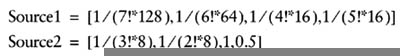
Setup One element of Source0 has to have the value in radians. Source1 and Source2 have to be set up with the following values to perform the expansion.
sincos r0.xy, r1.x, c4, c5
| LEGAL REGISTER ARGUMENTS | |||||||||
|---|---|---|---|---|---|---|---|---|---|
| | |||||||||
| DESTINATION | SOURCE | ||||||||
| PS version | v | c | t | r | v | c | t | r | s |
| | |||||||||
| 1.0 | |||||||||
| 1.1 | |||||||||
| 1.2 | |||||||||
| 1.3 | |||||||||
| 1.4 phase 1 | |||||||||
| 1.4 phase 2 | |||||||||
| 2.0 | x | x | x | x | x | ||||
| sub | ps 1.0–1.4 |
Subtracts the two source registers and stores them in the destination register.
One-arithmetic instruction slot.
_______________________________________________________________________________ sub Dest0, Source0, Source1 _______________________________________________________________________________
Subtracts Source1 from Source0 component by component and stores the result in Dest0.
sub r0, c0, v2
| tex | ps 1.0–1.3 |
Sample the color from the current texture stage and place it in the designation register.
No texture slots for PS 1.0; one for PS 1.1–1.3.
_______________________________________________________________________________ tex Dest0 _______________________________________________________________________________
Take the color from the current texture stage and place it in the destination register. The texture used is the one that's assigned to the current texture stage using SetTexture(). The texture coordinates are the output of the vertex shader oTn registers or the FFP.
The destination register must be a texture register. The texture sampled is associated with the number of the texture register used as the destination. For FFP, you can select the texture with the D3DTSS_TEXCOORDINDEX texture stage state flag.
| LEGAL REGISTER ARGUMENTS | ||||||||
|---|---|---|---|---|---|---|---|---|
| | ||||||||
| DESTINATION | SOURCE | |||||||
| PS version | v | c | t | r | v | c | t | r |
| | ||||||||
| 1.0 | x | x | x | x | x | |||
| 1.1 | x | x | x | x | x | x | ||
| 1.2 | x | x | x | x | x | x | ||
| 1.3 | x | x | x | x | x | x | ||
| 1.4 phase 1 | x | x | x | |||||
| 1.4 phase 2 | x | x | x | x | ||||
| 2.0 | x | x | x | x | x | |||
| LEGAL REGISTER ARGUMENTS | ||||
|---|---|---|---|---|
| | ||||
| DESTINATION | ||||
| PS version | v | c | t | r |
| | ||||
| 1.0 | x | |||
| 1.1 | x | |||
| 1.2 | x | |||
| 1.3 | x | |||
| 1.4 phase 1 | ||||
| 1.4 phase 2 | ||||
| 2.0 | ||||
| Note | This instruction cannot be used in PS 1.4 or 2.0 shaders. |
tex r0
| texbem | ps 1.0–1.3 |
2D Bump/Environment mapping.
One texture instruction slot.
_______________________________________________________________________________ texbem Dest0, Source0 _______________________________________________________________________________
The texbem instruction uses the .r and .g channels of the source texture as for du and dv perturbation values. The perturbation data is transformed by the 2 2 bump environment-mapping matrix, and then added to the current stage's texture coordinates. Then the current stage's texture is sampled and the results put into the destination register. Note that du and dv are treated as signed values.
The destination register must be a texture register. The texture sampled is associated with the number of the texture register used as the destination. The destination register number must be greater than the source register number.
For PS 1.0 and 1.1 The _bx2 input modifier cannot be used.
| Note | This instruction cannot be used in PS 1.4 or 2.0 shaders. |
| LEGAL REGISTER ARGUMENTS | ||||||||
|---|---|---|---|---|---|---|---|---|
| | ||||||||
| DESTINATION | SOURCE | |||||||
| PS version | v | c | t | r | v | c | t | r |
| | ||||||||
| 1.0 | x | x | ||||||
| 1.1 | x | x | ||||||
| 1.2 | x | x | ||||||
| 1.3 | x | x | ||||||
| 1.4 phase 1 | ||||||||
| 1.4 phase 2 | ||||||||
| 2.0 | ||||||||
Bug After using texbem or texbeml, the source register should be assumed to be corrupted and should not be read again without being reinitialized. Validation does not catch this.
texbem t1, t0
| texbeml | ps 1.0–1.3 |
2D Bump/Environment mapping with luminance correction.
One texture instruction slot.
_______________________________________________________________________________ texbeml Dest0, Source0 _______________________________________________________________________________
The texbem instruction uses the .r and .g channels of the source texture as for du and dv perturbation values. The perturbation data is transformed by the 2 2 bump environment-mapping matrix, and then added to the current stage's texture coordinates. Then the current stage's texture is sampled, a luminance correction is added, and the results put into the destination register. Note that du and dv are treated as signed values.
| LEGAL REGISTER ARGUMENTS | ||||||||
|---|---|---|---|---|---|---|---|---|
| | ||||||||
| DESTINATION | SOURCE | |||||||
| PS version | v | c | t | r | v | c | t | r |
| | ||||||||
| 1.0 | x | x | ||||||
| 1.1 | x | x | ||||||
| 1.2 | x | x | ||||||
| 1.3 | x | x | ||||||
| 1.4 phase 1 | ||||||||
| 1.4 phase 2 | ||||||||
| 2.0 | ||||||||
The luminance value and the bias texture stage are used to apply a luminance correction, and then these corrected values are used to sample the current stage's texture.
The destination register must be a texture register. The texture sampled is associated with the number of the texture register used as the destination. The destination register number must be greater than the source register number.
For PS 1.0 and 1.1 The _bx2 input modifier cannot be used.
| Note | This instruction cannot be used in PS 1.4 or 2.0 shaders. |
Bug After using texbem or texbeml, the source register should be assumed to be corrupted and should not be read again without being reinitialized. The validator does not catch this.
texbeml t0, t1
| texcoord | ps 1.0–1.3 |
Pass the texture coordinate values (u, v, w, 1) as color (r, g, b, 1).
One texture instruction slot.
_______________________________________________________________________________ texcoord Dest0 _______________________________________________________________________________
The texcoord instruction allows the programmer to pass texture coordinates into the shader as color values. No texture is sampled by this instruction. This means that, for example, if the vertex shader passed color values (or normals, etc.) in the texture coordinates registers (instead of texture coordinates), the values the texcoord instruction will pass in are the interpolated and perspective corrected values, just as if the values were texture coordinates. You might want to do this if you need higher precision values than the color registers provide. This allows any type of value (colors, normals, positions, texture coordinates) to get passed through the texture pipeline and be transformed by the same calculations that one would expect of texture coordinates.
If you are using the FFP, you'll need to use the D3DTSS_TEXCOORDINDEX texture stage state flag.
The values in the texture register contain xyzw values, but only the xyz values will be used. (Any missing texture coordinates will be set to 0. The w component will be set to 1.) The texture coordinate data is copied. The values are clamped to the range [0,1].
| Note | This instruction cannot be used in PS 1.4 or 2.0 shaders. |
texcoord t0
| LEGAL REGISTER ARGUMENTS | ||||
|---|---|---|---|---|
| | ||||
| DESTINATION | ||||
| PS version | v | c | t | r |
| | ||||
| 1.0 | x | |||
| 1.1 | x | |||
| 1.2 | x | |||
| 1.3 | x | |||
| 1.4 phase 1 | ||||
| 1.4 phase 2 | ||||
| 2.0 | ||||
| Texcrd | ps 1.4 |
Passes the texture coordinate data from the source into the destination register as color data. Similar to the texcoord instruction.
One texture instruction slot.
_______________________________________________________________________________ texcrd Dest0, Source0 _______________________________________________________________________________
Dest0 must be a temporary register, and Source0 must be a texture register. Only texture coordinates are passed by this instruction; no texture is sampled. The texture coordinate data is interpreted as color data. Unlike the texcoord instruction, the values are not clamped to the [0,1] range. The source register can hold data in the MaxTextureRepeat range, while the destination register can hold data in the MaxPixelShaderValue range (which is probably smaller), so you should be careful about the size of the source data.
| LEGAL REGISTER ARGUMENTS | ||||||||
|---|---|---|---|---|---|---|---|---|
| | ||||||||
| DESTINATION | SOURCE | |||||||
| PS version | v | c | t | r | v | c | t | r |
| | ||||||||
| 1.0 | ||||||||
| 1.1 | ||||||||
| 1.2 | ||||||||
| 1.3 | ||||||||
| 1.4 phase 1 | x | x | ||||||
| 1.4 phase 2 | x | x | ||||||
| 2.0 | ||||||||
| Note | You can pass only three coordinates with this instruction, as defined by the modifier, either .xyz or .xyw. If no mask is specified, the .xyz mask is assumed. The unused fourth channel (either z or w) will be undefined. |
You can perform a perspective divide using the _dw modifier on the fetched texture coordinates, in which case only .xy will be valid.
| Note | The D3DTTFF_PROJECTED flag is ignored. |
texcrd r2, t2.xyz texcrd r2, t2.xyw texcrd r2, t2_dw.xyw
| texdepth | ps 1.4 |
Calculates the depth value to be used in the depth test for this pixel. Uses r5 register.
One texture instruction slot.
_______________________________________________________________________________ texdepth Dest0 _______________________________________________________________________________
The Dest0 register can only be the r5 register, and this instruction can be used only in phase two. The instruction uses the value of (r5. r or r5. g) and uses that value as the pixel's depth value. The .r element is used as the z value, and the .g element as the w value. If r5.g is zero, the value of 1.0 will be used. Compare to the texm3x2depth instruction.
| LEGAL REGISTER ARGUMENTS | ||||
|---|---|---|---|---|
| | ||||
| DESTINATION | ||||
| PS version | v | c | t | r |
| | ||||
| 1.0 | ||||
| 1.1 | ||||
| 1.2 | ||||
| 1.3 | ||||
| 1.4 phase 1 | x | |||
| 1.4 phase 2 | ||||
| 2.0 | ||||
| Note | After using this instruction, you can't use the r5 register in the remainder of the pixel shader. |
texdepth r5
| texdp3 | ps 1.0, 1.3 |
Calculates a dot product using the (r, g, b) texture data in the source and destination texture coordinate data (u, v, w), and then stores the scalar result in the destination register.
One texture instruction slot.
_______________________________________________________________________________ texdp3 Dest0, Source0 _______________________________________________________________________________
The texdp3 takes the color data found in the texture specified by Source0's texture and performs a dot product on the texture coordinate data specified by the texture associated with Dest0's register number. The result is stored in all elements of Dest0. The register number of the Dest0 register must be greater than the Source0 texture register number. Assumes that a texture has already been loaded into Source0. The output is clamped to the range [0,1].
This instruction could be used to get a higher precision dp3 since it's performed by a texture-addressing instruction, then a color instruction.
| Note | This instruction cannot be used in PS 1.0, 1.1, 1.4, or 2.0 shaders. |
texdp3 t1, tO
| LEGAL REGISTER ARGUMENTS | ||||||||
|---|---|---|---|---|---|---|---|---|
| | ||||||||
| DESTINATION | SOURCE | |||||||
| PS version | v | c | t | r | v | c | t | r |
| | ||||||||
| 1.0 | ||||||||
| 1.1 | ||||||||
| 1.2 | x | x | ||||||
| 1.3 | x | x | ||||||
| 1.4 phase 1 | ||||||||
| 1.4 phase 2 | ||||||||
| 2.0 | ||||||||
| texdp3tex | ps 1.2, 1.3 |
Calculates a dot product using the (r, g, b) texture data in the source and destination texture coordinate data (u, v, w),and then uses the scalar result to sample the texture associated with the destination register. Useful as a texture lookup instruction when you store nontexture data in a texture.
One texture instruction slot.
_______________________________________________________________________________ texdp3tex Dest0, Source0 _______________________________________________________________________________
The texdp3tex takes the color data found in the texture specified by Source0's texture and performs a dot product on the texture coordinate data specified by the texture associated with Dest0's register number. The scalar result is then used to sample the texture data in the texture associated with Dest0. The result is stored in Dest0. The register number of the Dest0 register must be greater than the Source0 texture register number. Assumes that a texture has already been loaded into Source0.
| LEGAL REGISTER ARGUMENTS | ||||||||
|---|---|---|---|---|---|---|---|---|
| | ||||||||
| DESTINATION | SOURCE | |||||||
| PS version | v | c | t | r | v | c | t | r |
| | ||||||||
| 1.0 | ||||||||
| 1.1 | ||||||||
| 1.2 | x | x | ||||||
| 1.3 | x | x | ||||||
| 1.4 phase 1 | ||||||||
| 1.4 phase 2 | ||||||||
| 2.0 | ||||||||
You can use this instruction so that you can use a 1D texture as a lookup table. If you are using texm3x3*, you might consider using this instruction instead since it consumes fewer clocks.
| Note | This instruction cannot be used in PS 1.0, 1.1, 1.4, or 2.0 shaders. |
texdp3tex t1, t0
| texkill | ps 1.0–2.0 |
Terminates processing of the pixel if any of the values of the .xyz (for PS 1.0–1.4) or .xyzw (for PS 2.0) texture coordinates or registers are less than 0. Used to simulate clip planes, cheesy transparency, etc.
| LEGAL REGISTER ARGUMENTS | ||||
|---|---|---|---|---|
| | ||||
| DESTINATION | ||||
| PS version | v | c | t | r |
| | ||||
| 1.0 | x | |||
| 1.1 | x | |||
| 1.2 | x | |||
| 1.3 | x | |||
| 1.4 phase 1 | ||||
| 1.4 phase 2 | x | x | ||
| 2.0 | x | x | ||
One texture instruction slot.
texkill Source0
This instruction is used to instantly terminate processing of a pixel. No texture is sampled, but it uses the texture coordinates of the source register number (PS 1.0–1.3) or the data in the texture source register or the temporary register (PS 1.4). If in PS 1.4, it must be in phase two. If there are fewer than three texture coordinates, only those provided are used in the test. The _sat and _pp modifiers are not allowed.
| Note | If multisampling is enabled, you won't get an antialiasing effect along any texkill-generated edge. |
texkill t0
| texld | ps 1.4–2.0 |
Sample the texture and load the destination register with color data using the texture coordinates provided.
One texture instruction slot.
_______________________________________________________________________________ texld Dest0, Source0 // PS 1.4 texld Dest0, Source0, Sourcel // PS 2.0 _______________________________________________________________________________
For the PS 1.4 version This instruction samples the texture associated with the destination register using texture coordinates provided in the source register. The destination register must be a temporary register. If used in phase one, the source register must be a texture register; if in phase two, it can be a texture or temporary register. Texture registers produce a nondependent read, whereas temporary registers produce a dependent read. If you use a temporary as a source register, the x, y, and z elements must have been initialized in phase one.
For the PS 2.0 version Removed dependency on destination register. The Source 1 register must be a sampling register, where the register number identifies the texture to sample. Source0 provides the texture coordinates. The number of texture coordinates required to sample depends upon the declaration of the sampling register. For example, a cube map will require three texture coordinates to be provided. Signed textures will provide values in the [−1, 1] range, while unsigned textures will provide them in the [0,1] range. Sampling a texture with lower dimensions than provided is allowed, but it's a run-time error to attempt to sample from a texture that requires more texture coordinates than are provided. Also see the texldb and texldp instructions. You can't use the _sat modifier or a write mask on Dest0. You can't use negate or swizzles on the source registers.
| Note | The D3DTTFF_PROJECTED flag is ignored. For PS 1.4 you can use .xyz or .zyw modifiers on the texture registers as long as the same modifier is used in both phases. You can mix the .xyw modifier with the _dw modifier. You can use the _dz modifier only on a temporary register, but not more than twice per shader. |
| LEGAL REGISTER ARGUMENTS | ||||||||||||||
|---|---|---|---|---|---|---|---|---|---|---|---|---|---|---|
| | ||||||||||||||
| DESTINATION | SOURCE0 | SOURCE1 | ||||||||||||
| PS version | v | c | t | r | v | c | t | r | s | v | c | t | r | s |
| | ||||||||||||||
| 1.0 | ||||||||||||||
| 1.1 | ||||||||||||||
| 1.2 | ||||||||||||||
| 1.3 | ||||||||||||||
| 1.4 phase 1 | x | x | x | |||||||||||
| 1.4 phase 2 | x | x | x | x | x | |||||||||
| 2.0 | x | x | x | x | ||||||||||
// PS 1.4 texld r4, tO texld r4, tO.xyw texld r4, tO_dw.xyw // PS 2.0 texld r4, tO.xy, s3
| texldb | ps 2.0 |
Sample the texture and load the destination register with color data using the texture coordinates provided, biasing the mipmap level before sampling the texture.
| LEGAL REGISTER ARGUMENTS | ||||||||||||||
|---|---|---|---|---|---|---|---|---|---|---|---|---|---|---|
| | ||||||||||||||
| DESTINATION | SOURCE0 | SOURCE1 | ||||||||||||
| PS version | v | c | t | r | v | c | t | r | s | v | c | t | r | s |
| | ||||||||||||||
| 1.0 | ||||||||||||||
| 1.1 | ||||||||||||||
| 1.2 | ||||||||||||||
| 1.3 | ||||||||||||||
| 1.4 phase 1 | ||||||||||||||
| 1.4 phase 2 | ||||||||||||||
| 2.0 | x | x | x | x | ||||||||||
One texture instruction slot.
_______________________________________________________________________ texldb Dest0, Source0, Source1 _______________________________________________________________________
This instruction is a modification of the texld instruction, and all behavior and restrictions that apply to texld apply to this instruction as well. Also see the texld and texldp instructions.
In addition to sampling a texture as texld does, the texldb instruction uses the Source0.w element to bias the mipmap level. A positive value will bias towards smaller mipmaps, while a negative value will bias towards larger mipmaps. The acceptable range for the bias is [−3,+3]. Values outside this range will produce undefined results.
The D3DSAMP_MAXMIPLEVEL flag is valid and will be added to the bias specified here before sampling occurs.
texldb r4, tO, s2
| texldb | ps 2.0 |
Sample the texture and load the destination register with color data using the texture coordinates provided, performing a perspective projection on the texture coordinates before sampling the texture.
One texture instruction slot.
_______________________________________________________________________ texldp Dest0, Source0, Source1 _______________________________________________________________________
This instruction is a modification of the texld instruction, and all behavior and restrictions that apply to texld apply to this instruction as well. Also see the texld and texldb instructions.
| LEGAL REGISTER ARGUMENTS | ||||||||||||||
|---|---|---|---|---|---|---|---|---|---|---|---|---|---|---|
| | ||||||||||||||
| DESTINATION | SOURCE0 | SOURCE1 | ||||||||||||
| PS version | v | c | t | r | v | c | t | r | s | v | c | t | r | s |
| | ||||||||||||||
| 1.0 | ||||||||||||||
| 1.1 | ||||||||||||||
| 1.2 | ||||||||||||||
| 1.3 | ||||||||||||||
| 1.4 phase 1 | ||||||||||||||
| 1.4 phase 2 | ||||||||||||||
| 2.0 | x | x | x | x | ||||||||||
A perspective projection is performed on the texture coordinates prior to sampling. The texture coordinates are divided by Source0.w, then these projected coordinates are used for the sampling. Source0.w should never be zero.
The D3DTTFF_PROJECTED flag is not valid for PS 2.0
texldp r4, t0, s2
You can perform your own projection in the following code:
_______________________________________________________________________ // scale texture coordinates rcp Dest0.w, Source0.w mul Dest0, Source0, Dest0.w // you could warp coordinates here if desired // sample texture texld Dest0, Dest0, Source1 _______________________________________________________________________
| texm3x2depth | ps 1.3 |
Calculates the z and w depth values of the pixel. Used after setup by texm3x2pad. You might use this instruction for generating z value for sprites.
One texture instruction slot.
_______________________________________________________________________ texm3x2depth Dest0, Source0 _______________________________________________________________________
Assumes that texm3x2pad instruction was used to load a texture and set up a vector. This will be used as the depth z value. This instruction is used to calculate the depth w value. If the w value is zero, then the destination has a value of one stored in it. If the w value is not zero, then the destination has the value z/w stored in it. The result is not automatically clamped to the [0,1] range. The result is used as the depth value for the pixel, ignoring the existing pixel depth value.
| LEGAL REGISTER ARGUMENTS | ||||||||
|---|---|---|---|---|---|---|---|---|
| | ||||||||
| DESTINATION | SOURCE | |||||||
| PS version | v | c | t | r | v | c | t | r |
| | ||||||||
| 1.0 | ||||||||
| 1.1 | ||||||||
| 1.2 | ||||||||
| 1.3 | x | x | ||||||
| 1.4 phase 1 | ||||||||
| 1.4 phase 2 | ||||||||
| 2.0 | ||||||||
| Note | This instruction cannot be used in PS 1.0, 1.1, 1.2, 1.4, or 2.0 shaders. |
texm3x2depth t1, t0
| texm3x2pad | ps 1.0–1.3 |
Used with other pixel shader texture operations to perform 3 2 matrix multiplies.
One texture instruction slot.
_______________________________________________________________________ texm3x2pad Dest0, Source0 _______________________________________________________________________
This instruction is used to represent stages where only the texture coordinate is used. This instruction cannot be used by itself but is the setup instruction for a variety of other texture coordinate manipulating instructions. These corresponding stages have no textures bound, and no sampling will occur. The input argument, Source0, should still be specified.
| Note | This instruction cannot be used in PS 1.4 or 2.0 shaders. |
texm3x2pad t1, t0
| LEGAL REGISTER ARGUMENTS | ||||||||
|---|---|---|---|---|---|---|---|---|
| | ||||||||
| DESTINATION | SOURCE | |||||||
| PS version | v | c | t | r | v | c | t | r |
| | ||||||||
| 1.0 | x | x | ||||||
| 1.1 | x | x | ||||||
| 1.2 | x | x | ||||||
| 1.3 | x | x | ||||||
| 1.4 phase 1 | ||||||||
| 1.4 phase 2 | ||||||||
| 2.0 | ||||||||
| texm3x2tex | ps 1.0–1.3 |
Used with other pixel shader texture operations to perform 3 2 matrix multiplies. And does a texture lookup.
One texture instruction slot.
_______________________________________________________________________ texm3x2tex Dest0, Source0 _______________________________________________________________________
The texm3x2tex instruction is used with the texm3x2pad instruction. It performs a second matrix multiply and then samples the texture associated with Dest0.
| Note | This instruction cannot be used in PS 1.4 or 2.0 shaders. |
texm3x2tex t1, t0
| LEGAL REGISTER ARGUMENTS | ||||||||
|---|---|---|---|---|---|---|---|---|
| | ||||||||
| DESTINATION | SOURCE | |||||||
| PS version | v | c | t | r | v | c | t | r |
| | ||||||||
| 1.0 | x | x | ||||||
| 1.1 | x | x | ||||||
| 1.2 | x | x | ||||||
| 1.3 | x | x | ||||||
| 1.4 phase 1 | ||||||||
| 1.4 phase 2 | ||||||||
| 2.0 | ||||||||
| texm3x3 | ps 1.2, 1.3 |
Used with other pixel shader instructions. Used to perform the final stage of a 3 3 matrix multiply.
One texture instruction slot.
_______________________________________________________________________ texm3x3 Dest0, Source0 _______________________________________________________________________
This instruction must be used with the texm3x3pad instruction, which is used to set the first and second row of a 3 3 matrix multiply. The texm3x3 instruction will perform the third row multiply of the matrix multiply and store the three-element result in Dest0. The .a value of the destination is set to 1. Any textures associated with the registers are ignored. The register number associated with Dest0 must by higher than the register number associated with Source0. It assumes the source register has been loaded in some way. You can use this as a higher precision per pixel matrix transform.
| LEGAL REGISTER ARGUMENTS | ||||||||
|---|---|---|---|---|---|---|---|---|
| | ||||||||
| DESTINATION | SOURCE | |||||||
| PS version | v | c | t | r | v | c | t | r |
| | ||||||||
| 1.0 | ||||||||
| 1.1 | ||||||||
| 1.2 | x | x | ||||||
| 1.3 | x | x | ||||||
| 1.4 phase 1 | ||||||||
| 1.4 phase 2 | ||||||||
| 2.0 | ||||||||
| Note | This instruction cannot be used in PS 1.0, 1.1, 1.4 or 2.0 shaders. |
texm3x3 t1, t0
| texm3x3pad | ps 1.0–1.3 |
Used with other pixel shader texture operations to perform 3 3 matrix multiplies. This instruction is used as a set-up for a 3 3 multiply.
One texture instruction slot.
_______________________________________________________________________ texm3x3pad Dest0, Source0 _______________________________________________________________________
This instruction is used as the first and second part of a 3 3 matrix multiply operation performed in a pixel shader's texture declaration stage. It's used to perform the first and second row multiplies (with two instructions). Texture coordinates corresponding to the declared texture are used as a row of the matrix. No texture should be bound at this stage.
| LEGAL REGISTER ARGUMENTS | ||||||||
|---|---|---|---|---|---|---|---|---|
| | ||||||||
| DESTINATION | SOURCE | |||||||
| PS version | v | c | t | r | v | c | t | r |
| | ||||||||
| 1.0 | x | x | ||||||
| 1.1 | x | x | ||||||
| 1.2 | x | x | ||||||
| 1.3 | x | x | ||||||
| 1.4 phase 1 | ||||||||
| 1.4 phase 2 | ||||||||
| 2.0 | ||||||||
This instruction is used as a setup for the texm3x3, texm3x3spec, texm3x3tex, or texm3x3vspec instruction.
| Note | This instruction cannot be used in PS 1.4 or 2.0 shaders. |
texm3x3pad t1, t0
| texm3x3spec | ps 1.0–1.3 |
Performs specular reflection and environment mapping assuming a constant view direction. Used after setup by texm3x3pad.
One texture instruction slot.
_______________________________________________________________________ texm3x3spec Dest0, Source0, Source1 _______________________________________________________________________
This operation performs the final row multiplication of a 3 3 matrix multiply. It then takes the resulting vector and uses it as a normal vector. The value in Source1 is assumed to be a vector representing the eye direction. This vector is used with the normal vector to create a reflection vector, which is then used as the index for a texture lookup from the texture associated with the destination register. The result is stored in the destination register.
Both Dest0 and Source0 must be texture registers, while Source1 must be a constant register. No texture colors are sampled from the preceding two stages—that is, from the texture associated with the register numbers used by the two preceding texm3x3pad instructions that are required as setup for this instruction. The register number associated with Dest0 must be higher than the register number associated with Source0. The register number associated with Source0 must be higher than the register number associated with Source1. Compare with the texm3x3vspec instruction.
| LEGAL REGISTER ARGUMENTS | ||||||||||||
|---|---|---|---|---|---|---|---|---|---|---|---|---|
| | ||||||||||||
| DESTINATION | SOURCE0 | SOURCE1 | ||||||||||
| PS version | v | c | t | r | v | c | t | r | v | c | t | r |
| | ||||||||||||
| 1.0 | x | x | x | |||||||||
| 1.1 | x | x | x | |||||||||
| 1.2 | x | x | x | |||||||||
| 1.3 | x | x | x | |||||||||
| 1.4 phase 1 | ||||||||||||
| 1.4 phase 2 | ||||||||||||
| 2.0 | ||||||||||||
| Note | This instruction cannot be used in PS 1.4 or 2.0 shaders. |
texm3x3spec t1, t0, c3
| texm3x3tex | ps 1.0–1.3 |
Used with other pixel shader texture operations to perform 3 3 matrix multiply followed by a texture lookup. Used after setup by texm3x3pad.
One texture instruction slot.
_______________________________________________________________________ texm3x3tex Dest0, Source0 _______________________________________________________________________
The texm3x3tex instruction is used as the final of three instructions representing a 3 3 matrix multiply operation performed in a pixel shader's texture declaration. After the matrix multiplication, the resulting values are used as the (u, v, w) in a texture lookup into the texture associated with Dest0.
Both Dest0 and Source0 must be texture registers. No texture colors are sampled from the preceding two stages, and any texture associated with them is not sampled. The register number associated with Dest0 must be higher than the register number associated with Source0.
This instruction is typically used for transforming a normal vector into the correct tangent space and using it for look up.
| Note | This instruction cannot be used in PS 1.4 or 2.0 shaders. |
tex3x3tex t1, t0
| LEGAL REGISTER ARGUMENTS | ||||||||
|---|---|---|---|---|---|---|---|---|
| | ||||||||
| DESTINATION | SOURCE | |||||||
| PS version | v | c | t | r | v | c | t | r |
| | ||||||||
| 1.0 | x | x | ||||||
| 1.1 | x | x | ||||||
| 1.2 | x | x | ||||||
| 1.3 | x | x | ||||||
| 1.4 phase 1 | ||||||||
| 1.4 phase 2 | ||||||||
| 2.0 | ||||||||
| texm3x3vspec | ps 1.0–1.3 |
Performs specular reflection and environment mapping assuming a nonconstant view direction (i.e., a local viewer). Used after setup by texm3x3pad.
One texture instruction slot.
_______________________________________________________________________ texm3x3vspec Dest0, Source0 _______________________________________________________________________
This operation performs the final row multiplication of a 3 3 matrix multiply. It then takes the resulting vector and uses it as a normal vector. The view direction is taken from the w components of the three sets of texture coordinates used as rows of the matrix. This vector is used with the normal vector to create a reflection vector, which is then used as the index for a texture lookup from the texture associated with the destination register. The result is stored in the destination register.
| LEGAL REGISTER ARGUMENTS | ||||||||
|---|---|---|---|---|---|---|---|---|
| | ||||||||
| DESTINATION | SOURCE | |||||||
| PS version | v | c | t | r | v | c | t | r |
| | ||||||||
| 1.0 | x | x | ||||||
| 1.1 | x | x | ||||||
| 1.2 | x | x | ||||||
| 1.3 | x | x | ||||||
| 1.4 phase 1 | ||||||||
| 1.4 phase 2 | ||||||||
| 2.0 | ||||||||
You would use this instruction for a surface where you need specular highlights to vary with the eye direction. Both Dest0 and Source0 must be texture registers. No texture colors are sampled from the preceding two stages, and any texture associated with them is not sampled. The register number associated with Dest0 must be higher than the register number associated with Source0. Compare to the texm3x3spec instruction.
| Note | This instruction cannot be used in PS 1.4 or 2.0 shaders. |
texm3x3vspec t1, t0
| texreg2ar | ps 1.0–1.3 |
Samples the texture using the (a, r) texture coordinates of the source register as texture address data (u, v) at the stage corresponding to the destination register number, with the result being stored in the destination register.
One texture instruction slot.
_______________________________________________________________________ texreg2ar Dest0, Source0 _______________________________________________________________________
This instruction is used when you want to remap texture coordinates. The input color vector's alpha value is used as a u, and the red value is used as a v; the selected texture is sampled at these coordinates, and the value placed in the destination register. Both Source0 and Dest0 must be texture registers, and the actual register number of the Dest0 register must be greater than the Source0 texture register number. This assumes that you have already loaded a texture into Source0 and that values in Source0 are positive data.
| Note | This instruction cannot be used in PS 1.4 or 2.0 shaders. |
texreg2ar t1, t0 texreg2ar t0, t1 // Error! Source0 > Dest0
| LEGAL REGISTER ARGUMENTS | ||||||||
|---|---|---|---|---|---|---|---|---|
| | ||||||||
| DESTINATION | SOURCE | |||||||
| PS version | v | c | t | r | v | c | t | r |
| | ||||||||
| 1.0 | x | x | ||||||
| 1.1 | x | x | ||||||
| 1.2 | x | x | ||||||
| 1.3 | x | x | ||||||
| 1.4 phase 1 | ||||||||
| 1.4 phase 2 | ||||||||
| 2.0 | ||||||||
| texreg2gb | ps 1.0–1.3 |
Samples the texture using the (g, b) texture coordinates of the source register as texture address data (u, v) at the stage corresponding to the destination register number, with the result being stored in the destination register.
One texture instruction slot.
_______________________________________________________________________ texreg2gb Dest0, Source0 _______________________________________________________________________
This instruction is used when you want to remap texture coordinates. The input color vector's green value is used as a u, and the blue value is used as a v; the selected texture is sampled at these coordinates, and the value placed in the destination register. Both Source0 and Dest0 must be texture registers, and the actual register number of the Dest0 register must be greater than the Source0 texture register number. This assumes that you have already loaded a texture into Source0 and that values in Source0 are positive data.
| LEGAL REGISTER ARGUMENTS | ||||||||
|---|---|---|---|---|---|---|---|---|
| | ||||||||
| DESTINATION | SOURCE | |||||||
| PS version | v | c | t | r | v | c | t | r |
| | ||||||||
| 1.0 | x | x | ||||||
| 1.1 | x | x | ||||||
| 1.2 | x | x | ||||||
| 1.3 | x | x | ||||||
| 1.4 phase 1 | ||||||||
| 1.4 phase 2 | ||||||||
| 2.0 | ||||||||
| Note | This instruction cannot be used in PS 1.4 or 2.0 shaders. |
texreg2gb t1, t0 texreg2gb t0, t1 // Error! Source0 > Dest0
| texreg2rgb | ps 1.2, 1.3 |
Samples the texture using the (r, g, b) texture coordinates of the source register as texture address data at the stage corresponding to the destination register number, with the result being stored in the destination register.
One texture instruction slot.
_______________________________________________________________________ texreg2rgb Dest0, Source0 _______________________________________________________________________
| LEGAL REGISTER ARGUMENTS | ||||||||
|---|---|---|---|---|---|---|---|---|
| | ||||||||
| DESTINATION | SOURCE | |||||||
| PS version | v | c | t | r | v | c | t | r |
| | ||||||||
| 1.0 | ||||||||
| 1.1 | ||||||||
| 1.2 | x | x | ||||||
| 1.3 | x | x | ||||||
| 1.4 phase 1 | ||||||||
| 1.4 phase 2 | ||||||||
| 2.0 | ||||||||
This instruction is used when you want to remap texture coordinates. It works the same as texreg2ar and texreg2gb but adds support for 3D volumetric textures. The texture can be a 3D volumetric texture or a cube map. Both Source0 and Dest0 must be texture registers, and the actual register number of the Dest0 register must be greater than the Source0 texture register number. This assumes that you have already loaded a texture into Source0 and that values in Source0 are positive data.
| Note | This instruction cannot be used in PS 1.0, 1.1, 1.4, or 2.0 shaders. |
texreg2rgb t1, t0
|
|
EAN: 2147483647
Pages: 104