Parity Redundancy in RAID
| The concept of parity and checksum data has been used for many years in computer science to verify that data that has been transmitted has been transmitted accurately, without corruption. The basic concept of the checksum involves a sending node calculating a checksum value based on the data values that it was transmitting. This checksum value would then be placed at the end of the transmission. A receiving node receives the transmission and calculates its own checksum value for the data. If the receiver's checksum matched the transmitter's checksum, the data was considered to be accurate. If not, the receiver would discard the data and the transmitter would have to resend it. RAID applies a similar concept, but instead of using the checksum value to verify whether or not data was transmitted correctly, RAID parity values are used to reconstruct data that might be unreadable on an array member due to device, subsystem, or some other I/O path failure. Understood in the context of the original RAID research project, the basic idea of RAID was to create virtual storage and make multiple inexpensive disk drives act as if they were a single, larger, more expensive disk drive. One of the problems with that approach is that multiple inexpensive disk drives are much more likely to have failures than a single, large disk drive. In other words, the mean time between failure (MTBF) calculations for the multiple-drive RAID array were far less than a single drive. So, the RAID research team employed the idea of parity to overcome the expected reliability deficiencies of disk arrays. In a RAID array, if a disk drive or I/O component fails, RAID parity algorithms are used to combine the remaining data values with the parity values to reconstruct the original data on the fly. Table 9-1 shows data that the RAID controller writes as three data values and a single parity value. The top cell in each column indicates the status of the written data. In column 1 the data can be read without needing RAID to reconstruct data. Columns 2 to 4 show missing data that can be reconstructed using parity data. A RAID I/O operation can use any combination of two data values and the single parity values to reconstruct the original, missing data.
Reliability of Parity RAID ArraysAs mentioned previously, one of the design problems with aggregating disk drives in RAID arrays is the associated decreased reliability. To illustrate, assume there are members on ten different disk drives in an array; the result is that the array is ten times more likely to have a disk drive failure than a single drive. In other words, the MTBF of an array without parity is 10% of the MTBF calculation for its member drives. Obviously, it was imperative for RAID technology to be more reliable than individual disk drives if they were to succeed. With parity RAID, there must first be an initial failure before data is at risk due to another failure. The mean time to data loss (MTDL) after the first failure is 1/(N1) the MTBF of the drives used in the array, where N is the number of drives in the array. In other words, the MTDL of a parity RAID array before experiencing any failures is
Obviously, the reliability is best when N (the number of members) is a relatively small number. The larger N is, the closer the array's reliability is to the MTBF of a single member. This shows a fundamental problem with parity RAID: it has limited scalability because of the diminishing redundancy protection as you increase the number of members in an array. NOTE I'm often amazed when people ask me if it's possible to use two partitions on a single disk drive in the same array. This question is a real mind-blower. Not only would this put the data on the array at risk for a failure of a single disk drive, but it also creates a performance bottleneck where one would expect independent, overlapped I/Os. XOR ParityThe parity logic used in RAID uses a basic Boolean exclusive OR (XOR) function. The XOR algorithm is shown in Table 9-2 using the binary Boolean values of TRUE and FALSE. The determination of the XOR result is simple: two similar values create a FALSE result, and two different values create a TRUE result.
Properties of XORThe XOR function is remarkable in many ways. First, it is commutative, which means the calculation can be done in reverse order and still achieve the same result. Second, it is associative, which means the data values can be grouped differently to achieve the same result. This means that the parity calculation can be done using any arbitrary grouping of data values in any order. As long as all the data values are included once in the process, you get the same result. Parity can be calculated any number of ways using a simple, fast algorithm in either hardware or software. Table 9-3 shows all the possible combinations of four data values as well as the resulting parity value. Notice that you can arrange the data values in these rows any way you like, and you still get the same resulting parity value.
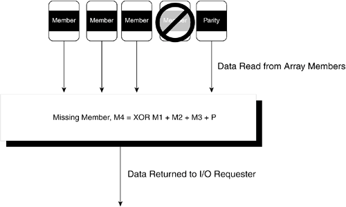
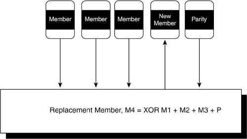
The other characteristic of XOR that makes it so useful for RAID is the fact that the XOR function is the inverse of itself. In other words, the exact same XOR function that creates parity from contributing members is also used to reconstruct missing data. For example, given a string of five data values, the XOR function is used to create a sixth parity value. Assume that in reading the data at a later time, the fifth data value is unreadable for some reason and needs to be reconstructed. Logically, it makes sense to apply an inverse process to the parity values to regenerate the missing data value. As it turns out, the inverse process happens to be the XOR function applied to the other four data values and the parity value. Referring to Table 9-3, you can try this out yourself and calculate any of the values in the rows by applying the XOR function to all the other values in the row. Degraded Mode OperationsWhen a member is unavailable and the XOR function in a RAID controller is being used to reconstruct data as it is being read, the RAID array controller is said to be operating in degraded mode. The term degraded refers not only to the fact that an element of the array is missing from operations, but the performance of the array controller also suffers from the added I/O and processing overhead. When the parity value is missing, as opposed to a data value, the array controller still operates in degraded mode, although the performance impact is minimal due to the fact that it is not necessary to reconstruct data. In RAID 5, which is by far the most common form of parity RAID, the parity data is spread across all members, which means a degraded mode operation always includes a minority of reads in which parity is the missing element. Figure 9-4 shows the basic functions of degraded mode operations for a five-member RAID 5 array. Figure 9-4. RAID Array Controller Operating in Degraded Mode Parity Rebuild OperationsThe basic principle of data reconstruction with parity allows array members to be removed and replaced in arrays and repopulated with data. When a member fails, the logic in the RAID controller removes the member from operations. Conversely, the controller can reinsert a new replacement member in the array. After the replacement member has been reinserted, a parity rebuild process can be run, which reads the remaining data values as well as the parity value and reconstructs the data for the failed member on the new member. Figure 9-5 shows the process of a parity rebuild. Figure 9-5. A RAID Parity Rebuild on a Replacement Member NOTE Parity rebuilds can have a significant performance impact on application I/O rates. Whereas mirroring can simply copy data from one member to another, the RAID parity rebuild has to read all data values and the parity value before calculating and writing the data to the replacement member. Obviously, the more members there are in an array, the more complicated this process is. It is clear that if an application process is generating heavy I/O traffic while the parity rebuild is running, there will be contention throughout the array for disk spindles and actuators. That's why parity rebuilds are often postponed until a time when system I/O activity is minimal. |
EAN: 2147483647
Pages: 184