Layer 2 Strategies
| < Day Day Up > |
| There are several Layer 2 availability design options. Layer 2 availability designs are desirable because any fault detection and recovery is transparent to the IP layer. Further, the fault detection and recovery can be relatively fast if the correct approach is taken. In this section, we explain the operation and recovery times for three approaches:
Trunking Approach to AvailabilityLink aggregation or trunking increases availability by distributing network traffic over multiple physical links. If one link breaks, the load on the broken link is transferred to the remaining links. IEEE 802.3ad is an industry standard created to allow the trunking solutions of various vendors to interoperate. Like most standards, there are many ways to implement the specifications. Link aggregation can be thought of as a layer of indirection between the MAC and PHY layers. Instead of having one fixed MAC address that is bound to a physical port, a logical MAC address is exposed to the IP layer and implements the Data Link Provider Interface (DLPI). This logical MAC address can be bound to many physical ports. The remote side must have the same capabilities and algorithm for distributing packets among the physical ports. FIGURE 6-2 shows a breakdown of the sublayers. Figure 6-2. Trunking Software Architecture
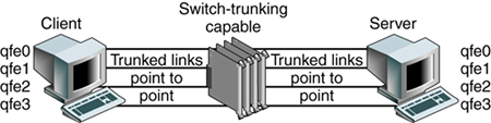
Theory of OperationThe Link Aggregation Control Protocol (LACP) allows both ends of the trunk to communicate trunking or link aggregation information. The first command sent is the Query command, where each link partner discovers the link aggregation capabilities of the other. If both partners are willing and capable, a Start Group command is sent. The Start Group command indicates that a link aggregation group is to be created followed by adding segments to this group that include link identifiers tied to the ports participating in the aggregation. The LACP can also delete a link, which might be due to the detection of a failed link. Instead of balancing the load across the remaining ports, the algorithm simply places the failed link's traffic onto one of the remaining links. The collector reassembles traffic coming from the different links. The distributor takes an input stream and spreads out the traffic across the ports belonging to a trunk group or link aggregation group. Availability IssuesTo understand suitability for network availability, Sun Trunking 1.2 software was installed on several quad fast Ethernet cards. The client has four trunks connected to the switch. The server also has four links connected to the switch. This setup allows the load to be distributed across the four links, as shown in FIGURE 6-3. Figure 6-3. Trunking Failover Test Setup
The highlighted line (in bold italic) in the CODE EXAMPLE 6-1 output shows the traffic from the client qfe0 moved to the server qfe1 under load balancing. Code example 6-1. Output Showing Traffic from Client qfe0 to Server qfe1Jan 10 14:22:05 2002 Name Ipkts Ierrs Opkts Oerrs Collis Crc %Ipkts %Opkts qfe0 210 0 130 0 0 0 100.00 25.00 qfe1 0 0 130 0 0 0 0.00 25.00 qfe2 0 0 130 0 0 0 0.00 25.00 qfe3 0 0 130 0 0 0 0.00 25.00 (Aggregate Throughput(Mb/sec): 5.73(New Peak) 31.51(Past Peak) 18.18%(New/Past)) Jan 10 14:22:06 2002 Name Ipkts Ierrs Opkts Oerrs Collis Crc %Ipkts %Opkts qfe0 0 0 0 0 0 0 0.00 0.00 qfe1 0 0 0 0 0 0 0.00 0.00 qfe2 0 0 0 0 0 0 0.00 0.00 qfe3 0 0 0 0 0 0 0.00 0.00 (Aggregate Throughput(Mb/sec): 0.00(New Peak) 31.51(Past Peak) 0.00%(New/Past)) Jan 10 14:22:07 2002 Name Ipkts Ierrs Opkts Oerrs Collis Crc %Ipkts %Opkts qfe0 0 0 0 0 0 0 0.00 0.00 qfe1 0 0 0 0 0 0 0.00 0.00 Jan 10 14:22:05 2002 qfe2 0 0 0 0 0 0 0.00 0.00 qfe3 0 0 0 0 0 0 0.00 0.00 (Aggregate Throughput(Mb/sec): 0.00(New Peak) 31.51(Past Peak) 0.00%(New/Past)) Jan 10 14:22:08 2002 Name Ipkts Ierrs Opkts Oerrs Collis Crc %Ipkts %Opkts qfe0 0 0 0 0 0 0 0.00 0.00 qfe1 1028 0 1105 0 0 0 100.00 51.52 qfe2 0 0 520 0 0 0 0.00 24.24 qfe3 0 0 520 0 0 0 0.00 24.24 (Aggregate Throughput(Mb/sec): 23.70(New Peak) 31.51(Past Peak) 75.21%(New/Past)) Several test transmission control protocol (TTCP) streams were pumped from one host to the other. When all links were up, the load was balanced evenly and each port experienced a 25 percent load. When one link was cut, the traffic of the failed link (qfe0) was transferred onto one of the remaining links (qfe1), which then showed a 51 percent load. The failover took three seconds. However, if all links were heavily loaded, the algorithm might force one link to be saturated with its original link load in addition to the failed link's traffic. For example, if all links were running at 55 percent capacity and one link failed, one link would be saturated at 55 percent + 55 percent = 110 percent traffic. Link aggregation is suitable for point-to-point links for increased availability, where nodes are on the same segment. However, there is a trade-off of port cost on the switch side as well as the host side. Load-Sharing PrinciplesThe Trunking Layer will break up packets on a frame boundary. This means as long as the server and switch know that a trunk is spanning certain physical ports, neither side needs to know about which algorithm is being used to distribute the load across the trunked ports. What is important is to understand the traffic characteristics in order to optimally distribute the load as evenly as possible across the trunked ports. The following diagrams describe how load sharing across trunks should be configured based on the nature of the traffic, which is often asymmetric. FIGURE 6-4 shows that a correct trunking policy on a switch with ingress traffic that has distributed Source IP address and Source MAC address can use a Trunking Policy based on round-robin, Source MAC/Destination MAC address, and Source IP/Destination IP address. Such a policy will distribute load evenly across physically trunked links. Figure 6-4. Correct Trunking Policy on Switch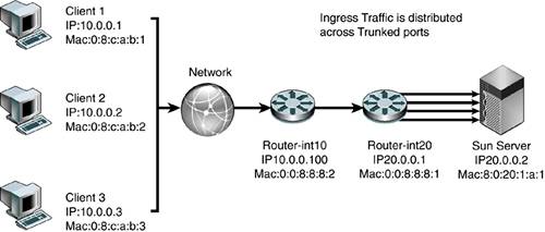 FIGURE 6-5 shows an incorrect trunking policy on a switch. In this case, the ingress traffic, which has single target IP address and target MAC, should not use a trunking policy based solely on the destination IP address or destination or source MAC. Figure 6-5. Incorrect Trunking Policy on Switch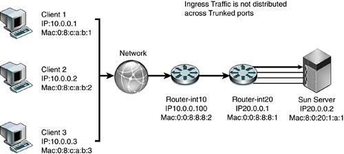 FIGURE 6-6 shows a correct trunking policy on a server with egress traffic that has distributed target IP address, but the target MAC of the default router should only use a trunking policy based on round-robin or destination IP address. A destination MAC will not work because the destination MAC will only point to the default router :0:0:8:8:1, not the actual client MAC. Figure 6-6. Correct Trunking Policy on Server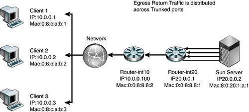 FIGURE 6-7 shows an incorrect trunking policy on the server. In this example, the egress traffic has a distributed target IP address, but the target MAC of the default router should not use a trunking policy based on the destination MAC because the destination MAC will only point to the default router :0:0:8:8:1, not the actual client MAC. Trunking policy should not use either the source IP address or the source MAC. The trunking policy should use the target IP addresses because that will spread the load across the physical interfaces evenly. Figure 6-7. Incorrect Trunking Policy on a Server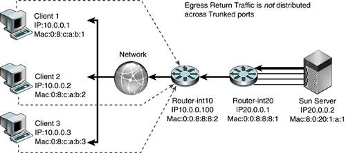 FIGURE 6-8 shows an incorrect trunking policy on a server. Even though the egress traffic is using round-robin, it is not distributing the load evenly because all the traffic belongs to the same session. In this case, trunking is not effective in distributing load across physical interfaces. Figure 6-8. Incorrect Trunking Policy on a Server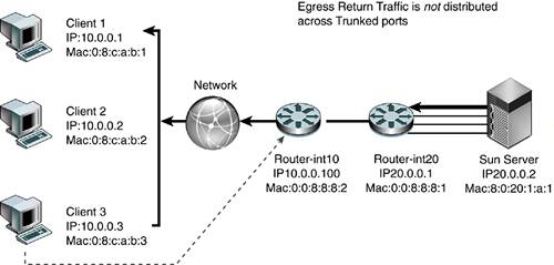 Availability Strategies Using SMLT and DMLTIn the past, server network resiliency leveraged IPMP and VRRP. Our deployments revealed that network switches with relatively low-powered CPUs had problems processing large numbers of ping requests due to ICMP health checks when combined with other control processing such as VRRP routing calculations. Network switches were not designed to process a steady stream of ping requests in a timely manner. Ping requests were traditionally used occasionally to troubleshoot network issues. Hence, processing of ping requests was a lower priority than processing routing updates and other control plane network tasks. As the number of IPMP nodes increases, the network switch soon runs out of CPU processing resources and drops ping requests. This results in IPMP nodes falsely detecting router failures, which often result in a ping-pong effect of failing over back and forth across interfaces. One recent advance, introduced in NortelNetworks switches, is called Split MultiLink Trunking (SMLT) and Distributed Multilink Trunking (DMLT). In this section, we describe several key tested configurations using NortelNetworks Passport 8600 Core switches and the smaller Layer 2 switches NortelNetworks Business Policy Switch 2000. These configurations illustrate how network high availability can be achieved without encountering the scalability issues that have plagued IPMP and VRRP deployments. SMLT is a Layer 2 trunking redundancy mechanism. It is similar to plain trunking except that it spans two physical devices. FIGURE 6-9 shows a typical SMLT deployment using two NortelNetworks Passport 8600 Switches and a Sun server with dual GigaSwift cards. The trunk spans both cards, but each card is connected to a separate switch. SMLT technology, in effect, exposes one logical trunk to the Sun server, when actually there are two physically separate devices. Figure 6-9. Layer 2 High-Availability Design Using SMLT
FIGURE 6-10 shows another integration point where workgroup servers connect to the corporate network at an edge point. In this case, instead of integrating directly into the enterprise core, the servers connect to a smaller Layer 2 switch, which runs DMLT, a scaled version of the SMLT, but similar in functionality. DMLT has fewer features and a smaller binary image than SMLT. This means that DMLT can run on smaller network devices. The switches are viewed as one logical trunking device even though packets are load shared across the links, with the switches ensuring packets arrive in order at the remote destination. FIGURE 6-10 illustrates a server-to-edge integration of a Layer 2 high-availability design using Sun Trunking 1.3 and NortelNetworks Business Policy 2000 Wiring Closet Edge Switches. Figure 6-10. Layer 2 High-Availability Design Using DMLT
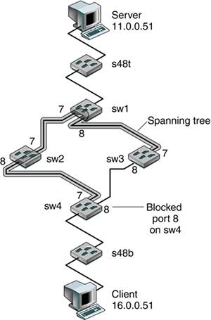
CODE EXAMPLE 6-2 shows a sample configuration of the Passport 8600. Code example 6-2. Sample Configuration of the Passport 8600# # MLT CONFIGURATION PASSPORT 8600 # # mlt 1 create mlt 1 add ports 1/1,1/8 mlt 1 name "IST Trunk" mlt 1 perform-tagging enable mlt 1 ist create ip 10.19.10.2 vlan-id 10 mlt 1 ist enable mlt 2 create mlt 2 add ports 1/6 mlt 2 name "SMLT-1" mlt 2 perform-tagging enable mlt 2 smlt create smlt-id 1 # Availability Using Spanning Tree ProtocolThe spanning tree algorithm was developed by Radia Perlman, currently with Sun Microsystems. The Spanning Tree Protocol (STP) is used on Layer 2 networks to eliminate loops. For added availability, redundant Layer 2 links can be added. However, these redundant links introduce loops, which cause bridges to forward frames indefinitely. By introducing STP, bridges communicate with each other by sending bridge protocol data units (BPDUs), which contain information that a bridge uses to determine which ports forward traffic and which ports don't based on the spanning tree algorithm. A typical BPDU contains information including a unique bridge identifier, the port identifier, and cost to the root bridge, which is the top of the spanning tree. From these BPDUs, each bridge can compute a spanning tree and decide which ports to direct all forwarding of traffic. If a link fails, this tree is recomputed, and redundant links are activated by turning on certain ports hence creating increased availability. A network needs to be designed to ensure that every possible link that could fail has some redundant link. In older networks, bridges are still used. However, with recent advances in network switch technology and smaller Layer 2 networks, bridges are not used as much. Availability IssuesTo better understand failure detection and recovery, a testbed was created, as shown in FIGURE 6-11. Figure 6-11. Spanning Tree Network Setup
The switches sw1, sw2, sw3, and sw4 were configured in a Layer 2 network with an obvious loop, which was controlled by running the STP among these switches. On the client, we ran the traceroute server command, resulting in the following output, which shows that the client sees only two Layer 3 networks: the 11.0.0.0 and the 16.0.0.0 network. client># traceroute server traceroute: Warning: Multiple interfaces found; using 16.0.0.51 @ hme0 traceroute to server (11.0.0.51), 30 hops max, 40 byte packets 1 16.0.0.1 (16.0.0.1) 1.177 ms 0.524 ms 0.512 ms 2 16.0.0.1 (16.0.0.1) 0.534 ms !N 0.535 ms !N 0.529 ms !N Similarly, the server sees only two Layer 3 networks. We ran the traceroute client command on the server and got the following output: server># traceroute client traceroute: Warning: Multiple interfaces found; using 11.0.0.51 @ hme0 traceroute to client (16.0.0.51), 30 hops max, 40 byte packets 1 11.0.0.1 (11.0.0.1) 0.756 ms 0.527 ms 0.514 ms 2 11.0.0.1 (11.0.0.1) 0.557 ms !N 0.546 ms !N 0.531 ms !N The following outputs show the STP configuration and port status of the participating switches, showing the port MAC address of the root switches. * sw1:17 # sh s0 ports 7-8 Stpd: s0 Port: 7 PortId: 4007 Stp: ENABLED Path Cost: 4 Port State: FORWARDING Topology Change Ack: FALSE Port Priority: 16 Designated Root: 80:00:00:01:30:92:3f:00 Designated Cost: 0 Designated Bridge: 80:00:00:01:30:92:3f:00 Designated Port Id: 4007 Stpd: s0 Port: 8 PortId: 4008 Stp: ENABLED Path Cost: 4 Port State: FORWARDING Topology Change Ack: FALSE Port Priority: 16 Designated Root: 80:00:00:01:30:92:3f:00 Designated Cost: 0 Designated Bridge: 80:00:00:01:30:92:3f:00 Designated Port Id: 4008 * sw2:12 # sh s0 ports 7-8 Port Mode State Cost Flags Priority Port ID Designated Bridge 7 802.1D FORWARDING 4 e-R-- 16 16391 80:00:00:01:30:92:3f:00 8 802.1D FORWARDING 4 e-D-- 16 16392 80:00:00:01:30:92:3f:00 Total Ports: 8 Flags: e=Enable, d=Disable, T=Topology Change Ack R=Root Port, D=Designated Port, A=Alternative Port * sw3:5 # sh s0 ports 7-8 Stpd: s0 Port: 7 PortId: 4007 Stp: ENABLED Path Cost: 4 Port State: FORWARDING Topology Change Ack: FALSE Port Priority: 16 Designated Root: 80:00:00:01:30:92:3f:00 Designated Cost: 0 Designated Bridge: 80:00:00:01:30:92:3f:00 Designated Port Id: 4001 Stpd: s0 Port: 8 PortId: 4008 Stp: ENABLED Path Cost: 4 Port State: FORWARDING Topology Change Ack: FALSE Port Priority: 16 Designated Root: 80:00:00:01:30:92:3f:00 Designated Cost: 4 Designated Bridge: 80:00:00:e0:2b:98:96:00 Designated Port Id: 4008 The following output shows that STP has blocked Port 8 on sw4. * sw4:10 # sh s0 ports 7-8 Stpd: s0 Port: 7 PortId: 4007 Stp: ENABLED Path Cost: 4 Port State: FORWARDING Topology Change Ack: FALSE Port Priority: 16 Designated Root: 80:00:00:01:30:92:3f:00 Designated Cost: 4 Designated Bridge: 80:00:00:01:30:f4:16:a0 Designated Port Id: 4008 Stpd: s0 Port: 8 PortId: 4008 Stp: ENABLED Path Cost: 4 Port State: BLOCKING Topology Change Ack: FALSE Port Priority: 16 Designated Root: 80:00:00:01:30:92:3f:00 Designated Cost: 4 Designated Bridge: 80:00:00:e0:2b:98:96:00 Designated Port Id: 4008 To get a better understanding of failure detection and fault recovery, we conducted a test where the client continually sent a ping to the server, and we pulled a cable on the spanning tree path. The following output shows that it took approximately 58 seconds for failure detection and recovery, which is not acceptable in most mission-critical environments. (Each ping takes about one second. The following output shows that from icmp_seq=16 to icmp_seq=74, the pings did not succeed.) on client --------- 4 bytes from server (11.0.0.51): icmp_seq=12. time=1. ms 64 bytes from server (11.0.0.51): icmp_seq=13. time=1. ms 64 bytes from server (11.0.0.51): icmp_seq=14. time=1. ms 64 bytes from server (11.0.0.51): icmp_seq=15. time=1. ms 64 bytes from server (11.0.0.51): icmp_seq=16. time=1. ms ICMP Net Unreachable from gateway 16.0.0.1 for icmp from client (16.0.0.51) to server (11.0.0.51) ... ... ICMP Net Unreachable from gateway 16.0.0.1 for icmp from client (16.0.0.51) to server (11.0.0.51) ICMP Net Unreachable from gateway 16.0.0.1 for icmp from client (16.0.0.51) to server (11.0.0.51) for icmp from client (16.0.0.51) to server (11.0.0.51) 64 bytes from server (11.0.0.51): icmp_seq=74. time=1. ms 64 bytes from server (11.0.0.51): icmp_seq=75. time=1. ms 64 bytes from server (11.0.0.51): icmp_seq=76. |

| < Day Day Up > |
EAN: 2147483647
Pages: 116