Layer 3 Strategies
| < Day Day Up > |
| There are several Layer 3 availability design options. Layer 3 availability designs are desirable because there could be a fault at the IP layer, but not at the lower layers. By implementing a Layer 3 availability strategy, we can infer the status of the network at all layers below, but not at the layers above. The fault detection and recovery can be relatively slower than Layer 2 strategies, depending on the strategy. In this section we explain the operation and recovery times for three approaches:
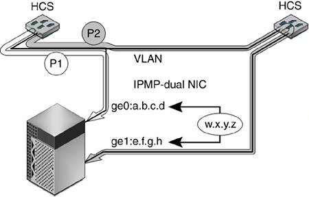
We describe how these network design strategies work and actually tested configurations. VRRP Router RedundancyThe Virtual Router Redundancy Protocol (VRRP) was designed to remove a single point of failure where hosts connected to the rest of the enterprise network or Internet through one default router. The VRRP is based on an election algorithm, where there are two routers: one master that owns both a MAC and an IP address and one that is a backup. Both routers reside on one LAN or VLAN segment. The hosts all point to one IP address that points to the master router. The master and backup constantly send multicast messages to each other. Depending on the vendor-specific implementation, the backup will assume the master role if the master is no longer functioning or has lowered in priority based on some criteria. The new master also assumes the same MAC address so that the clients do not need to update their Address Resolution Protocol (ARP) caches. The VRRP, by itself, has left open many aspects so that switch manufacturers can implement and add features to differentiate themselves. All vendors offer a variety of features that alter the priority, which can be tied to server health checks, number of active ports, and so on. Whichever router has the highest priority becomes the master. These configurations need to be closely monitored to prevent oscillations. Often, a switch is configured to be too sensitive, causing it to constantly change priority and hence fluctuate between master and backup. IPMP Host Network Interface RedundancyThe purpose of the server redundant network interface capability is to increase overall system availability. If one server NIC fails, the backup will take over within two seconds. This is IP Multipathing (IPMP) on the Solaris operating system. IPMP is a feature bundled with the Solaris operating system that is crucial in creating highly available network designs. IPMP has a daemon that constantly sends pings to the default router, which is intelligently pulled from the kernel routing tables. If that router is not reachable, another standby interface in the same IPMP group then assumes ownership of the floating IP address. The switch re-runs the ARP for the new MAC address and can contact the server again. A typical highly available configuration includes a Sun server with dual NIC cards, which increases the availability of these components by several orders of magnitude. For example, the GigabitEthernet card, part number 595-5414-01, by itself has an MTBF of 199156 hours, and assuming approximately two hours' mean time to recovery (MTTR), it has an availability of 0.999989958. With two cards, the MTBF becomes nine 9's at .9999999996 availability. This small incremental cost has a big impact on the overall availability computation. FIGURE 6-12 shows the Sun server redundant NIC model using IPMP. The server has two NICs, ge0 and ge1, with a fixed IP addresses of a.b.c.d and e.f.g.h. The virtual IP address of w.x.y.z is the IP address of the service. Client requests use this IP address as the destination. This IP address floats between the two interfaces ge0 or ge1. Only one interface can be associated with the virtual IP address at any one time. If the ge0 interface owns the virtual IP address, then data traffic will follow the P1 path. If the ge0 interface fails, then the ge1 interface will take over and associate the virtual IP address and data traffic will follow the P2 path. Failures can be detected within two seconds, depending on the configuration. Figure 6-12. High-Availability Network Interface Cards on Sun Servers
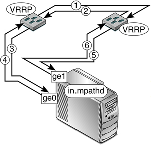
Integrated VRRP and IPMPBy combining the availability technologies of routers and server NICs, we can create a cell that can be reused in any deployment where servers are connected to routers. This reusable cell is highly available and scalable. FIGURE 6-13 shows how this is implemented. Lines 1 and 2 show the VRRP protocol used by the routers to monitor each other. If one router detects that the other has failed, the surviving router assumes the role of master and inherits the IP address and MAC address of the master. Figure 6-13. Design Pattern IPMP and VRRP Integrated Availability Solution
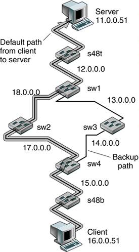
Lines 3 and 5 in FIGURE 6-13 show how a switch can verify that a particular connection is up and running. This verification can be port-based, link-based, or based on Layers 3, 4, and 7. The router can make synthetic requests to the server and verify that a particular service is up and running. If it detects that the service has failed, then the VRRP can be configured, on some switches, to take this into consideration to impact the election algorithm and tie this failure to the priority of the VRRP router. Simultaneously, the server also monitors links. Currently, IPMP consists of a daemon, in.mpathd, that constantly sends pings to the default router. As long as the default router can receive a ping, the master interface (ge0) assumes ownership of the IP address. If the in.mpathd daemon detects that the default router is not reachable, automatic failover will occur, which brings down the link and floats the IP address of the server to the surviving interface (ge1). In the lab, we can tune IPMP and Extreme Standby Routing Protocol (ESRP) to achieve failure detection and recovery within one second. Because the ESRP is a CPU-intensive task and the control packets are on the same network as the production network, the trade-off is that if the switches, networks, or servers become overloaded, false failures can occur because the device can take longer than the strict timeout to respond to the peer's heartbeat. OSPF Network Redundancy Rapid ConvergenceOpen Shortest Path First (OSPF) is an intra-domain, link-state routing protocol. The main idea of OSPF is that each OSPF router can determine the state of the link to all neighbor routers and the costs associated with sending data over that link. One property of this routing protocol is that each OSPF router has a view of the entire network, which allows it to find the best path to all participating routers. All OSPF routers in the domain flood each other with link state packets (LSPs), which contain the unique ID of the sending router; a list of directly connected neighbor routers and associated costs; a sequence number and a time to live, authentication, hierarchy, and load balancing; and checksum information. From this information, each node can reliably determine if this LSP is the most recent by comparing seq numbers and computing the shortest path to every node and then collecting all LSPs from all nodes and comparing costs using Dijstras' shortest path algorithm. To prevent continuous flooding, the sender never receives the same LSP packet that it sent out. To better understand OSPF for suitability from an availability perspective, the following lab network was set up, consisting of Extreme Network switches and Sun servers. FIGURE 6-14 describes the actual setup used to demonstrate availability characteristics of the interior routing protocol OSPF. Figure 6-14. Design Pattern OSPF Network
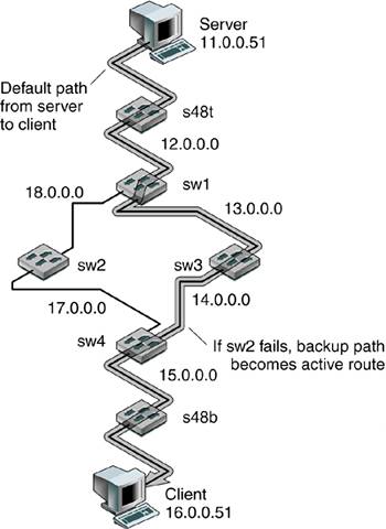
To confirm correct configuration, traceroute commands were issued from client to server. In the following output, the highlighted lines show the path through sw2: client># traceroute server traceroute: Warning: Multiple interfaces found; using 16.0.0.51 @ hme0 traceroute to server (11.0.0.51), 30 hops max, 40 byte packets 1 16.0.0.1 (16.0.0.1) 1.168 ms 0.661 ms 0.523 ms 2 15.0.0.1 (15.0.0.1) 1.619 ms 1.104 ms 1.041 ms 3 17.0.0.1 (17.0.0.1) 1.527 ms 1.197 ms 1.043 ms 4 18.0.0.1 (18.0.0.1) 1.444 ms 1.208 ms 1.106 ms 5 12.0.0.1 (12.0.0.1) 1.237 ms 1.274 ms 1.083 ms 6 server (11.0.0.51) 0.390 ms 0.349 ms 0.340 ms The following tables show the initial routing tables of the core routers. The first two highlighted lines in CODE EXAMPLE 6-3 show the route to the client through sw2. The second two highlighted lines show the sw2 path. Code example 6-3. Router sw1 Routing TableOR Destination Gateway Mtr Flags Use M-Use VLAN Acct-1 *s 10.100.0.0/24 12.0.0.1 1 UG---S-um 63 0 net12 0 *oa 11.0.0.0/8 12.0.0.1 5 UG-----um 98 0 net12 0 *d 12.0.0.0/8 12.0.0.2 1 U------u- 1057 0 net12 0 *d 13.0.0.0/8 13.0.0.1 1 U------u- 40 0 net13 0 *oa 14.0.0.0/8 13.0.0.2 8 UG-----um 4 0 net13 0 *oa 15.0.0.0/8 18.0.0.2 12 UG-----um 0 0 net18 0 *oa 15.0.0.0/8 13.0.0.2 12 UG-----um 0 0 net13 0 *oa 16.0.0.0/8 18.0.0.2 13 UG-----um 0 0 net18 0 *oa 16.0.0.0/8 13.0.0.2 13 UG-----um 0 0 net13 0 *oa 17.0.0.0/8 18.0.0.2 8 UG-----um 0 0 net18 0 *d 18.0.0.0/8 18.0.0.1 1 U------u- 495 0 net18 0 *d 127.0.0.1/8 127.0.0.1 0 U-H----um 0 0 Default 0 Origin(OR): b - BlackHole, bg - BGP, be - EBGP, bi - IBGP, bo - BOOTP, ct - CBT d - Direct, df - DownIF, dv - DVMRP, h - Hardcoded, i - ICMP mo - MOSPF, o - OSPF, oa - OSPFIntra, or - OSPFInter, oe - OSPFAsExt o1 - OSPFExt1, o2 - OSPFExt2, pd - PIM-DM, ps - PIM-SM, r - RIP ra - RtAdvrt, s - Static, sv - SLB_VIP, un - UnKnown. Flags: U - Up, G - Gateway, H - Host Route, D - Dynamic, R - Modified, S - Static, B - BlackHole, u - Unicast, m - Multicast. Total number of routes = 12. Mask distribution: 11 routes at length 8 1 routes at length 24 Code example 6-4. Router sw2 Routing Tablesw2:8 # sh ipr OR Destination Gateway Mtr Flags Use M-Use VLAN Acct-1 *s 10.100.0.0/24 18.0.0.1 1 UG---S-um 27 0 net18 0 *oa 11.0.0.0/8 18.0.0.1 9 UG-----um 98 0 net18 0 *oa 12.0.0.0/8 18.0.0.1 8 UG-----um 0 0 net18 0 *oa 13.0.0.0/8 18.0.0.1 8 UG-----um 0 0 net18 0 *oa 14.0.0.0/8 17.0.0.2 8 UG-----um 0 0 net17 0 *oa 15.0.0.0/8 17.0.0.2 8 UG-----um 9 0 net17 0 *oa 16.0.0.0/8 17.0.0.2 9 UG-----um 0 0 net17 0 *d 17.0.0.0/8 17.0.0.1 1 U------u- 10 0 net17 0 *d 18.0.0.0/8 18.0.0.2 1 U------u- 403 0 net18 0 *d 127.0.0.1/8 127.0.0.1 0 U-H----um 0 0 Default 0 # # Code example 6-5. Router sw3 Routing Tablesw3:5 # sh ipr OR Destination Gateway Mtr Flags Use M-Use VLAN Acct-1 *s 10.100.0.0/24 13.0.0.1 1 UG---S-um 26 0 net13 0 *oa 11.0.0.0/8 13.0.0.1 9 UG-----um 0 0 net13 0 *oa 12.0.0.0/8 13.0.0.1 8 UG-----um 121 0 net13 0 *d 13.0.0.0/8 13.0.0.2 1 U------u- 28 0 net13 0 *d 14.0.0.0/8 14.0.0.1 1 U------u- 20 0 net14 0 *oa 15.0.0.0/8 14.0.0.2 8 UG-----um 0 0 net14 0 *oa 16.0.0.0/8 14.0.0.2 9 UG-----um 0 0 net14 0 *oa 17.0.0.0/8 14.0.0.2 8 UG-----um 0 0 net14 0 *oa 18.0.0.0/8 13.0.0.1 8 UG-----um 0 0 net13 0 *d 127.0.0.1/8 127.0.0.1 0 U-H----um 0 0 Default 0 The first two highlighted lines in CODE EXAMPLE 6-6 show the route back to the server through sw4. The second two highlighted lines show the sw2 path. Code example 6-6. Switch sw4 Routing Tablesw4:8 # sh ipr OR Destination Gateway Mtr Flags Use M-Use VLAN Acct-1 *s 10.100.0.0/24 14.0.0.1 1 UG---S-um 29 0 net14 0 *oa 11.0.0.0/8 17.0.0.1 13 UG-----um 0 0 net17 0 *oa 11.0.0.0/8 14.0.0.1 13 UG-----um 0 0 net14 0 *oa 12.0.0.0/8 17.0.0.1 12 UG-----um 0 0 net17 0 *oa 12.0.0.0/8 14.0.0.1 12 UG-----um 0 0 net14 0 *oa 13.0.0.0/8 14.0.0.1 8 UG-----um 0 0 net14 0 *d 14.0.0.0/8 14.0.0.2 1 U------u- 12 0 net14 0 *d 15.0.0.0/8 15.0.0.1 1 U------u- 204 0 net15 0 *oa 16.0.0.0/8 15.0.0.2 5 UG-----um 0 0 net15 0 *d 17.0.0.0/8 17.0.0.2 1 U------u- 11 0 net17 0 *oa 18.0.0.0/8 17.0.0.1 8 UG-----um 0 0 net17 0 *d 127.0.0.1/8 127.0.0.1 0 U-H----um 0 0 Default 0 To check failover capabilities on the OSPF, the interface on the switch sw2 was damaged to create a failure and a constant ping command was run from the client to the server. The interface on the switch sw2 was removed, and the measurement of failover was performed as shown in the following output. The first highlighted line shows when the interface sw2 fails. The second highlighted line shows that the new switch interface sw3 route is established in two seconds. client reading: 64 bytes from server (11.0.0.51): icmp_seq=11. time=2. ms 64 bytes from server (11.0.0.51): icmp_seq=12. time=2. ms ICMP Net Unreachable from gateway 17.0.0.1 for icmp from client (16.0.0.51) to server (11.0.0.51) ICMP Net Unreachable from gateway 17.0.0.1 for icmp from client (16.0.0.51) to server (11.0.0.51) 64 bytes from server (11.0.0.51): icmp_seq=15. time=2. ms 64 bytes from server (11. OSPF took approximately two seconds to detect and recover from the failed node. The highlighted lines in the following output from the traceroute server command shows the new path from the client to the server through the switch interface sw3. client># traceroute server traceroute: Warning: Multiple interfaces found; using 16.0.0.51 @ hme0 traceroute to server (11.0.0.51), 30 hops max, 40 byte packets 1 16.0.0.1 (16.0.0.1) 0.699 ms 0.535 ms 0.581 ms 2 15.0.0.1 (15.0.0.1) 1.481 ms 0.990 ms 0.986 ms 3 14.0.0.1 (14.0.0.1) 1.214 ms 1.021 ms 1.002 ms 4 13.0.0.1 (13.0.0.1) 1.322 ms 1.088 ms 1.100 ms 5 12.0.0.1 (12.0.0.1) 1.245 ms 1.131 ms 1.220 ms 6 server (11.0.0.51) 1.631 ms 1.200 ms 1.314 ms The following code examples show the routing tables after the node failure. The first highlighted line in CODE EXAMPLE 6-7 shows the new route to the server through the switch sw3. The second highlighted line shows that the switch sw2 link is down. Code example 6-7. Switch sw1 Routing Table After Node Failuresw1:27 # sh ipr OR Destination Gateway Mtr Flags Use M-Use VLAN Acct-1 *s 10.100.0.0/24 12.0.0.1 1 UG---S-um 63 0 net12 0 *oa 11.0.0.0/8 12.0.0.1 5 UG-----um 168 0 net12 0 *d 12.0.0.0/8 12.0.0.2 1 U------u- 1083 0 net12 0 *d 13.0.0.0/8 13.0.0.1 1 U------u- 41 0 net13 0 *oa 14.0.0.0/8 13.0.0.2 8 UG-----um 4 0 net13 0 *oa 15.0.0.0/8 13.0.0.2 12 UG-----um 0 0 net13 0 *oa 16.0.0.0/8 13.0.0.2 13 UG-----um 22 0 net13 0 *oa 17.0.0.0/8 13.0.0.2 12 UG-----um 0 0 net13 0 d 18.0.0.0/8 18.0.0.1 1 --------- 515 0 -------- 0 *d 127.0.0.1/8 127.0.0.1 0 U-H----um 0 0 Default 0 Code example 6-8. Switch sw2 Routing Table After Node Failuresw1:4 # sh ipr OR Destination Gateway Mtr Flags Use M-Use VLAN Acct-1 *s 10.100.0.0/24 12.0.0.1 1 UG---S-um 63 0 net12 0 *oa 11.0.0.0/8 12.0.0.1 5 UG-----um 168 0 net12 0 *d 12.0.0.0/8 12.0.0.2 1 U------u- 1102 0 net12 0 *d 13.0.0.0/8 13.0.0.1 1 U------u- 41 0 net13 0 *oa 14.0.0.0/8 13.0.0.2 8 UG-----um 4 0 net13 0 *oa 15.0.0.0/8 13.0.0.2 12 UG-----um 0 0 net13 0 *oa 16.0.0.0/8 13.0.0.2 13 UG-----um 22 0 net13 0 *oa 17.0.0.0/8 13.0.0.2 12 UG-----um 0 0 net13 0 d 18.0.0.0/8 18.0.0.1 1 --------- 515 0 -------- 0 *d 127.0.0.1/8 127.0.0.1 0 U-H----um 0 0 Default 0 Code example 6-9. Switch sw3 Routing Table After Node Failuresw3:6 # sh ipr OR Destination Gateway Mtr Flags Use M-Use VLAN Acct-1 *s 10.100.0.0/24 13.0.0.1 1 UG---S-um 26 0 net13 0 *oa 11.0.0.0/8 13.0.0.1 9 UG-----um 24 0 net13 0 *oa 12.0.0.0/8 13.0.0.1 8 UG-----um 134 0 net13 0 *d 13.0.0.0/8 13.0.0.2 1 U------u- 29 0 net13 0 *d 14.0.0.0/8 14.0.0.1 1 U------u- 20 0 net14 0 *oa 15.0.0.0/8 14.0.0.2 8 UG-----um 0 0 net14 0 *oa 16.0.0.0/8 14.0.0.2 9 UG-----um 25 0 net14 0 *oa 17.0.0.0/8 14.0.0.2 8 UG-----um 0 0 net14 0 *d 127.0.0.1/8 127.0.0.1 0 U-H----um 0 0 Default 0 The highlighted line in CODE EXAMPLE 6-10 shows the new route back to the client through sw3. Code example 6-10. Switch sw4 Routing Table After Node Failure sw4:9 # sh ipr OR Destination Gateway Mtr Flags Use M-Use VLAN Acct-1 *s 10.100.0.0/24 14.0.0.1 1 UG---S-um 29 0 net14 0 *oa 11.0.0.0/8 14.0.0.1 13 UG-----um 21 0 net14 0 *oa 12.0.0.0/8 14.0.0.1 12 UG-----um 0 0 net14 0 *oa 13.0.0.0/8 14.0.0.1 8 UG-----um 0 0 net14 0 *d 14.0.0.0/8 14.0.0.2 1 U------u- 12 0 net14 0 *d 15.0.0.0/8 15.0.0.1 1 U------u- 216 0 net15 0 *oa 16.0.0.0/8 15.0.0.2 5 UG-----um 70 0 net15 0 *d 17.0.0.0/8 17.0.0.2 1 U------u- 12 0 net17 0 *d 127.0.0.1/8 127.0.0.1 0 U-H----um 0 0 Default 0 OSPF is a good routing protocol with enterprise networks. It has fast failure detection and recovery. RIP Network RedundancyThe Routing Information Protocol (RIP) is based on the Bellman-Ford distance vector algorithm. The idea behind the RIP is that each RIP router builds a one-dimensional array that contains a scalar notion of hops to reach all other hops. (In theory, OSPF was able to use the notion of cost with greater accuracy, which could capture information such as link speed. However, in actual practice, this might not be practical because of the increased burden of maintaining correct link costs in large changing environments.) RIP routers flood each other with their view of the network by first starting with directly connected neighbor routers and then modifying their vector if peer updates show that there is a shorter path. After a few updates, a complete routing table is constructed. When a router detects a failure, the distance is updated to infinity. Ideally, all routers would eventually receive the proper update and adjust their tables accordingly. However, if the network is designed with redundancy, there can be issues in properly updating the tables to reflect a failed link. There are problems such as count to infinity that have fixes such as "split horizon" and "poison reverse." The RIP was a first implementation of the distance vector algorithm. The RIPv2, the most common, addresses scalability and other limitations of the RIP. To better understand the failover capabilities of RIPv2, the test network shown in FIGURE 6-15 was set up. Figure 6-15. RIP Network Setup
The following output shows the server-to-client path before node failure. The highlighted lines show the path through the switch sw3. server># traceroute client traceroute: Warning: Multiple interfaces found; using 11.0.0.51 @ hme0 traceroute to client (16.0.0.51), 30 hops max, 40 byte packets 1 11.0.0.1 (11.0.0.1) 0.711 ms 0.524 ms 0.507 ms 2 12.0.0.2 (12.0.0.2) 1.448 ms 0.919 ms 0.875 ms 3 13.0.0.2 (13.0.0.2) 1.304 ms 0.977 ms 0.964 ms 4 14.0.0.2 (14.0.0.2) 1.963 ms 1.091 ms 1.151 ms 5 15.0.0.2 (15.0.0.2) 1.158 ms 1.059 ms 1.037 ms 6 client (16.0.0.51) 1.560 ms 1.170 ms 1.107 ms The following code examples show the initial routing tables. The highlighted line in CODE EXAMPLE 6-11 shows the path to the client through the switch sw3. Code example 6-11. Switch sw1 Initial Routing Table OR Destination Gateway Mtr Flags Use M-Use VLAN Acct-1 *s 10.100.0.0/24 12.0.0.1 1 UG---S-um 32 0 net12 0 *r 11.0.0.0/8 12.0.0.1 2 UG-----um 15 0 net12 0 *d 12.0.0.0/8 12.0.0.2 1 U------u- 184 0 net12 0 *d 13.0.0.0/8 13.0.0.1 1 U------u- 52 0 net13 0 *r 14.0.0.0/8 13.0.0.2 2 UG-----um 1 0 net13 0 *r 15.0.0.0/8 18.0.0.2 3 UG-----um 0 0 net18 0 *r 16.0.0.0/8 13.0.0.2 4 UG-----um 10 0 net13 0 *r 17.0.0.0/8 18.0.0.2 2 UG-----um 0 0 net18 0 *d 18.0.0.0/8 18.0.0.1 1 U------u- 12 0 net18 0 *d 127.0.0.1/8 127.0.0.1 0 U-H----um 0 0 Default 0 Code example 6-12. Switch sw2 Initial Routing Tablesw2:3 # sh ipr OR Destination Gateway Mtr Flags Use M-Use VLAN Acct-1 *s 10.100.0.0/24 18.0.0.1 1 UG---S-um 81 0 net18 0 *r 11.0.0.0/8 18.0.0.1 3 UG-----um 9 0 net18 0 *r 12.0.0.0/8 18.0.0.1 2 UG-----um 44 0 net18 0 *r 13.0.0.0/8 18.0.0.1 2 UG-----um 0 0 net18 0 *r 14.0.0.0/8 17.0.0.2 2 UG-----um 0 0 net17 0 *r 15.0.0.0/8 17.0.0.2 2 UG-----um 0 0 net17 0 *r 16.0.0.0/8 17.0.0.2 3 UG-----um 3 0 net17 0 *d 17.0.0.0/8 17.0.0.1 1 U------u- 17 0 net17 0 *d 18.0.0.0/8 18.0.0.2 1 U------u- 478 0 net18 0 *d 127.0.0.1/8 127.0.0.1 0 U-H----um 0 0 Default 0 # # Code example 6-13. Switch sw3 Initial Routing Tablesw3:3 # sh ipr OR Destination Gateway Mtr Flags Use M-Use VLAN Acct-1 *s 10.100.0.0/24 13.0.0.1 1 UG---S-um 79 0 net13 0 *r 11.0.0.0/8 13.0.0.1 3 UG-----um 3 0 net13 0 *r 12.0.0.0/8 13.0.0.1 2 UG-----um 44 0 net13 0 *d 13.0.0.0/8 13.0.0.2 1 U------u- 85 0 net13 0 *d 14.0.0.0/8 14.0.0.1 1 U------u- 33 0 net14 0 *r 15.0.0.0/8 14.0.0.2 2 UG-----um 0 0 net14 0 *r 16.0.0.0/8 14.0.0.2 3 UG-----um 10 0 net14 0 *r 17.0.0.0/8 14.0.0.2 2 UG-----um 0 0 net14 0 *r 18.0.0.0/8 13.0.0.1 2 UG-----um 0 0 net13 0 *d 127.0.0.1/8 127.0.0.1 0 U-H----um 0 0 Default 0 The highlighted line in CODE EXAMPLE 6-14 shows the path to the server through the switch sw3. Code example 6-14. Switch sw4 Initial Routing Table sw4:7 # sh ipr OR Destination Gateway Mtr Flags Use M-Use VLAN Acct-1 *s 10.100.0.0/24 14.0.0.1 1 UG---S-um 29 0 net14 0 *r 11.0.0.0/8 14.0.0.1 4 UG-----um 9 0 net14 *r 12.0.0.0/8 14.0.0.1 3 UG-----um 0 0 net14 0 *r 13.0.0.0/8 14.0.0.1 2 UG-----um 0 0 net14 0 *d 14.0.0.0/8 14.0.0.2 1 U------u- 13 0 net14 0 *d 15.0.0.0/8 15.0.0.1 1 U------u- 310 0 net15 0 *r 16.0.0.0/8 15.0.0.2 2 UG-----um 16 0 net15 0 *d 17.0.0.0/8 17.0.0.2 1 U------u- 3 0 net17 0 *r 18.0.0.0/8 17.0.0.1 2 UG-----um 0 0 net17 0 *d 127.0.0.1/8 127.0.0.1 0 U-H----um 0 0 Default 0 The highlighted lines in the following output from running the traceroute client command show the new path from the server to the client through the switch sw2 after the switch sw3 fails. server># traceroute client traceroute: Warning: Multiple interfaces found; using 11.0.0.51 @ hme0 traceroute to client (16.0.0.51), 30 hops max, 40 byte packets 1 11.0.0.1 (11.0.0.1) 0.678 ms 0.479 ms 0.465 ms 2 12.0.0.2 (12.0.0.2) 1.331 ms 0.899 ms 0.833 ms 3 18.0.0.2 (18.0.0.2) 1.183 ms 0.966 ms 0.953 ms 4 17.0.0.2 (17.0.0.2) 1.379 ms 1.082 ms 1.062 ms 5 15.0.0.2 (15.0.0.2) 1.101 ms 1.024 ms 0.993 ms 6 client (16.0.0.51) 1.209 ms 1.086 ms 1.074 ms The following output shows the result of the server ping commands 64 bytes from client (16.0.0.51): icmp_seq=18. time=2. ms 64 bytes from client (16.0.0.51): icmp_seq=19. time=2. ms 64 bytes from client (16.0.0.51): icmp_seq=20. time=2. ms ICMP Net Unreachable from gateway 12.0.0.2 for icmp from server (11.0.0.51) to client (16.0.0.51) ICMP Net Unreachable from gateway 12.0.0.2 .. .. for icmp from server (11.0.0.51) to client (16.0.0.51) ICMP Net Unreachable from gateway 12.0.0.2 for icmp from server (11.0.0.51) to client (16.0.0.51) ICMP Net Unreachable from gateway 12.0.0.2 for icmp from server (11.0.0.51) to client (16.0.0.51) 64 bytes from client (16.0.0.51): icmp_seq=41. time=2. ms 64 bytes from client (16.0.0.51): icmp_seq=42. time=2. ms 64 bytes from client (16.0.0.51): icmp_seq=43. time=2. ms The fault detection and recovery took in excess of 21 seconds. The RIPv2 is widely available. However, the failure detection and recovery is not optimal. |
| < Day Day Up > |
EAN: 2147483647
Pages: 116