| One of the first items to consider for network availability is the architecture itself. Network architectures fall into two basic categories: flat and multi-level. A flat architecture is composed of a multi-layer switch that performs multiple switching functions in one physical network device. This implies that a packet will traverse fewer network switching devices when communicating from the client to the server. This results in higher availability. A multi-level architecture is composed of multiple small switches where each switch performs one or two switching functions. This implies that a packet will traverse more network switching devices when communicating from the client to the server. This results in a lower availability.
Serial components reduce availability and parallel components increase availability. A serial design requires that every component is functioning at the same time. If any one component fails, the entire system fails. A parallel design offers multiple paths in case one path fails. In a parallel design, if any one component fails, the entire system still survives by using the backup path. Three network architecture aspects impact network availability: Component failure This aspect is the probability of the device failing. It is measured using statistics averaging the amount of time the device works divided by the average time the device works plus the failed time. This value is called the MTBF. In calculating the MTBF, components that are connected serially dramatically reduce the MTBF, while components that are in parallel increase the MTBF. System failure This aspect captures failures that are caused by external factors, such as a technician accidentally pulling out a cable. The number of components that are potential candidates for failure is directly proportional to the complexity of the system. Design B in FIGURE 6-1 has more components that can go wrong, which contributes to the increased probability of failure. Figure 6-1. Network Topologies and Impact on Availability 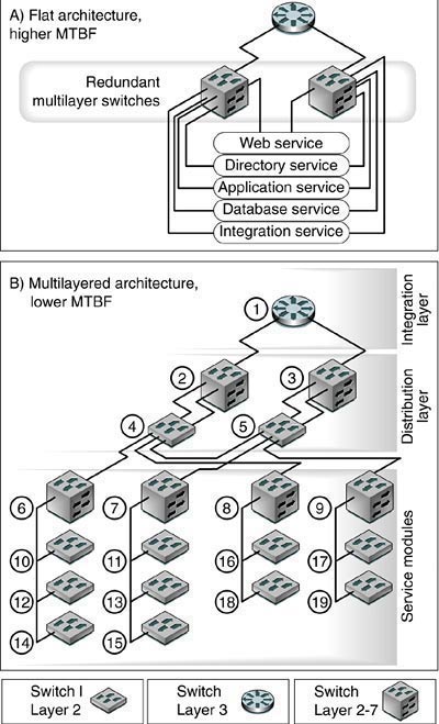
Single points of failure This aspect captures the number of devices that can fail and still have the system functioning. Neither Design A nor Design B shown in FIGURE 6-1 has a single point of failure (SPOF), so they are equal in this regard. However, Design B is somewhat more resilient because if a network interface card (NIC) fails, that failure is isolated by the Layer 2 switch and does not impact the rest of the architecture. This issue has a trade-off to consider, where availability is sacrificed for increased resiliency and isolation of failures. FIGURE 6-1 shows two network designs. In both designs, Layer 2 switches provide physical connectivity for one virtual local area network (VLAN) domain. Layer 2-7 switches are multilayer devices providing routing, load balancing, and other IP services in addition to physical connectivity. Design A shows a flat architecture, often seen with multilayer chassis-based switches using Extreme Networks Black Diamond, Foundry Networks BigIron, or Cisco switches. The switch can be partitioned into VLANs, isolating traffic from one segment to another, yet providing a much better overall solution. In this approach, the availability will be relatively high because there are two parallel paths from the ingress to each server and only two serial components that a packet must traverse to reach the target server. In Design B, the architecture provides the same functionality, but across many small switches. From an availability perspective, this solution will have a relatively lower mean time between failures (MTBF) because there are more serial components that a packet must traverse to reach a target server. Other disadvantages of this approach include manageability, scalability, and performance. However, one can argue that there might be increased security using this approach, which for some customers outweighs all other factors. In Design B, multiple switches must be hacked to control the network, whereas in Design A, only one switch needs to be hacked to bring down the entire network.
|