Foundation Topics
VLAN Trunking ProtocolAs the previous chapter demonstrated, VLAN configuration and trunking on a switch or a small group of switches is fairly intuitive. Campus network environments, however, usually consist of many interconnected switches. Configuring and managing a large number of switches, VLANs, and VLAN trunks quickly can get out of control. Cisco has developed a method to manage VLANs across the campus network. The VLAN Trunking Protocol (VTP) uses Layer 2 trunk frames to communicate VLAN information among a group of switches. VTP manages the addition, deletion, and renaming of VLANs across the network from a central point of control. Any switch participating in a VTP exchange is aware of and can use any VLAN that VTP manages. VTP DomainsVTP is organized into management domains, or areas with common VLAN requirements. A switch can belong to only one VTP domain, in addition to sharing VLAN information with other switches in the domain. Switches in different VTP domains, however, do not share VTP information. Switches in a VTP domain advertise several attributes to their domain neighbors. Each advertisement contains information about the VTP management domain, VTP revision number, known VLANs, and specific VLAN parameters. When a VLAN is added to a switch in a management domain, other switches are notified of the new VLAN through VTP advertisements. In this way, all switches in a domain can prepare to receive traffic on their trunk ports using the new VLAN. VTP ModesTo participate in a VTP management domain, each switch must be configured to operate in one of several modes. The VTP mode determines how the switch processes and advertises VTP information. You can use the following modes:
Tip While a switch is in VTP transparent mode, it can create and delete VLANs that are local only to itself. These VLAN changes, however, are not propagated to any other switch. VTP AdvertisementsEach Cisco switch participating in VTP advertises VLANs (only VLANs 1 to 1005), revision numbers, and VLAN parameters on its trunk ports to notify other switches in the management domain. VTP advertisements are sent as multicast frames. The switch intercepts frames sent to the VTP multicast address and processes them with its supervisory processor. VTP frames are forwarded out trunk links as a special case. Because all switches in a management domain learn of new VLAN configuration changes, a VLAN must be created and configured only on one VTP server switch in the domain. By default, management domains are set to use nonsecure advertisements without a password. You can add a password to set the domain to secure mode. The same password must be configured on every switch in the domain so that all switches exchanging VTP information use identical encryption methods. The VTP advertisement process starts with configuration revision number 0 (zero). When subsequent changes are made, the revision number is incremented before advertisements are sent. When listening switches (configured as members of the same VTP domain as the advertising switch) receive an advertisement with a greater revision number than is stored locally, the advertisement overwrites any stored VLAN information. Because of this, it is very important to always force any newly added network switches to have revision number 0 before being attached to the network. The VTP revision number is stored in NVRAM and is not altered by a power cycle of the switch. Therefore, the revision number can be initialized only to 0 using one of the following methods:
If the VTP revision number is not reset to 0, the switch might enter the network as a VTP server and have a pre-existing revision number (from a previous life) that is higher than in previous legitimate advertisements. The new switch's VTP information would be seen as more recent, so all other switches in the VTP domain gladly would accept its database of VLANs and overwrite their good VLAN database entries with null or deleted VLAN status information. In other words, a new server switch inadvertently might cause every other working switch to flush all records of every VLAN in production. This is referred to as a VTP synchronization problem. Advertisements can originate as requests from client-mode switches that want to learn about the VTP database at bootup. Advertisements also cam originate from server-mode switches as VLAN configuration changes occur. VTP advertisements can occur in three forms:
Catalyst switches in server mode store VTP information separately from the switch configuration in NVRAM. VLAN and VTP data are saved in the vlan.dat file on the switch's Flash memory file system. All VTP information, including the VTP configuration revision number, is retained even when the switch power is off. In this manner, a switch can recover the last known VLAN configuration from its VTP database after it reboots. VTP ConfigurationBy default, every switch operates in VTP server mode for the management domain NULL (a blank string), with no password or secure mode. If the switch hears a VTP summary advertisement on a trunk port from any other switch, it automatically learns the VTP domain name, VLANs, and the configuration revision number it hears. This makes it easy to bring up a new switch in an existing VTP domain. However, be aware that the new switch stays in VTP server mode, something that might not be desirable. Tip You should get into the habit of double-checking the VTP configuration of any switch before you add it into your network. Make sure the VTP configuration revision number is set to zero. You can do this by isolating the switch from the network, powering it up, and using the show vtp status command, as demonstrated in the following output: Switch# show vtp status VTP Version : 2 Configuration Revision : 0 Maximum VLANs supported locally : 1005 Number of existing VLANs : 5 VTP Operating Mode : Server VTP Domain Name : VTP Pruning Mode : Disabled VTP V2 Mode : Disabled VTP Traps Generation : Disabled MD5 digest : 0x57 0xCD 0x40 0x65 0x63 0x59 0x47 0xBD Configuration last modified by 0.0.0.0 at 0-0-00 00:00:00 Local updater ID is 0.0.0.0 (no valid interface found) Switch#The following sections discuss the commands and considerations that you should use to configure a switch for VTP operation. You should be aware that there are two supported ways to configure VLAN and VTP information in Catalyst IOS switches:
The vlan database EXEC command still is supported in Catalyst IOS Software only for backward-compatibility, but this is not covered in the BCMSN course or the exam. Configuring a VTP Management DomainBefore a switch is added into a network, the VTP management domain should be identified. If this switch is the first one on the network, the management domain must be created. Otherwise, the switch might have to join an existing management domain with other existing switches. You can use the following global configuration command to assign a switch to a management domain, where the domain-name is a text string up to 32 characters long: Switch(config)# vtp domain domain-name Configuring the VTP ModeNext, you need to choose the VTP mode for the new switch. The three VTP modes of operation and their guidelines for use are as follows:
Keeping switches in transparent mode can eliminate the chance for duplicate, overlapping VLANs in a large network with many network administrators. For example, two administrators might configure VLANs on switches in their respective areas but use the same VLAN identification or VLAN number. Even though the two VLANs have different meanings and purposes, they could overlap if both administrators advertised them using VTP servers. You can configure the VTP mode with the following sequence of global configuration commands: Switch(config)# vtp mode {server | client | transparent} Switch(config)# vtp password password If the domain is operating in secure mode, a password also can be defined. The password can be configured only on VTP servers and clients. It builds an MD5 digest that is sent in VTP advertisements (servers) and is used to validate received advertisements (clients). The password is a string of 1 to 32 characters (case-sensitive). If secure VTP is implemented using passwords, begin by configuring a password on the VTP servers. The client switches retain the last-known VTP information but cannot process received advertisements until the same password is configured on them, too. Configuring the VTP VersionTwo versions of VTP are available for use in a management domain. Catalyst switches are capable of running either VTP version 1 or VTP version 2. Within a management domain, the two versions are not interoperable. Therefore, the same VTP version must be configured on every switch in a domain. VTP version 1 is the default protocol on a switch. If a switch is capable of running VTP version 2, however, a switch can coexist with other version 1 switches, as long as its VTP version 2 is not enabled. This situation becomes important if you want to use version 2 in a domain. Then only one server mode switch needs to have VTP version 2 enabled. The new version number is propagated to all other version 2capable switches in the domain, causing them all to automatically enable version 2 for use. Tip A third version of VTP addresses some of the traditional shortcomings. For example, VTP version 3 supports extended VLAN numbers (1 to 4095) that are compatible with the IEEE 802.1Q trunking standard. At press time, VTPv3 is available only on Cisco Catalyst platforms running the CatOS (non-IOS) operating system. Therefore, only VTP versions 1 and 2 are covered on the BCMSN exam and in this text. The two versions of VTP differ in the features they support. VTP version 2 offers the following additional features over version 1:
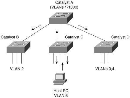
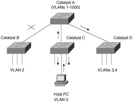
The VTP version number is configured using the following global configuration command: Switch(config)# vtp version {1 | 2} By default, a switch uses VTP version 1. VTP Configuration ExampleAs an example, a switch is configured as the VTP server in a domain named MyCompany. The domain will use secure VTP with the password bigsecret. You can use the following configuration commands to accomplish this: Switch(config)# vtp domain MyCompany Switch(config)# vtp mode server Switch(config)# vtp password bigsecret VTP StatusThe current VTP parameters for a management domain can be displayed using the show vtp status command. Example 7-1 demonstrates some sample output of this command from a switch acting as a VTP client in the VTP domain called CampusDomain. Example 7-1. show vtp status Reveals VTP Parameters for a Management DomainSwitch# show vtp status VTP Version : 2 Configuration Revision : 89 Maximum VLANs supported locally : 1005 Number of existing VLANs : 74 VTP Operating Mode : Client VTP Domain Name : CampusDomain VTP Pruning Mode : Enabled VTP V2 Mode : Disabled VTP Traps Generation : Disabled MD5 digest : 0x4B 0x07 0x75 0xEC 0xB1 0x3D 0x6F 0x1F Configuration last modified by 192.168.199.1 at 11-19-02 09:29:56 Switch#VTP message and error counters also can be displayed with the show vtp counters command. You can use this command for basic VTP troubleshooting to see if the switch is interacting with other VTP nodes in the domain. Example 7-2 demonstrates some sample output from the show vtp counters command. Example 7-2. show vtp counters Reveals VTP Message and Error CountersSwitch# show vtp counters VTP statistics: Summary advertisements received : 1 Subset advertisements received : 2 Request advertisements received : 1 Summary advertisements transmitted : 1630 Subset advertisements transmitted : 0 Request advertisements transmitted : 4 Number of config revision errors : 0 Number of config digest errors : 0 Number of V1 summary errors : 0 VTP pruning statistics: Trunk Join Transmitted Join Received Summary advts received from non-pruning-capable device ---------------- ---------------- ---------------- --------------------------- Gi0/1 82352 82931 0 Switch#VTP PruningRecall that, by definition, a switch must forward broadcast frames out all available ports in the broadcast domain because broadcasts are destined everywhere there is a listener. Unless forwarded by more intelligent means, multicast frames follow the same pattern. In addition, frames destined for an address that the switch has not yet learned or has forgotten (the MAC address has aged out of the address table) must be forwarded out all ports in an attempt to find the destination. These frames are referred to as unknown unicast. When forwarding frames out all ports in a broadcast domain or VLAN, trunk ports are included if they transport that VLAN. By default, a trunk link transports traffic from all VLANs, unless specific VLANs are removed from the trunk. Generally, in a network with several switches, trunk links are enabled between switches, and VTP is used to manage the propagation of VLAN information. This scenario causes the trunk links between switches to carry traffic from all VLANs, not just from the specific VLANs created. Consider the network shown in Figure 7-4. When end user HostPC in VLAN 3 sends a broadcast, Catalyst switch C forwards the frame out all VLAN 3 ports, including the trunk link to Catalyst A. Catalyst A, in turn, forwards the broadcast on to Catalysts B and D over those trunk links. Catalysts B and D forward the broadcast out only their access links that have been configured for VLAN 3. If Catalysts B and D do not have any active users in VLAN 3, forwarding that broadcast frame to them would consume bandwidth on the trunk links and processor resources in both switches, only to have switches B and D discard the frames. Figure 7-4. Flooding in a Catalyst Switch Network VTP pruning makes more efficient use of trunk bandwidth by reducing unnecessary flooded traffic. Broadcast and unknown unicast frames on a VLAN are forwarded over a trunk link only if the switch on the receiving end of the trunk has ports in that VLAN. VTP pruning occurs as an extension to VTP version 1, using an additional VTP message type. When a Catalyst switch has a port associated with a VLAN, the switch sends an advertisement to its neighbor switches that it has active ports on that VLAN. The neighbors keep this information, enabling them to decide whether flooded traffic from a VLAN should use a trunk port. Figure 7-5 shows the network from Figure 7-4 with VTP pruning enabled. Because Catalyst B has not advertised its use of VLAN 3, Catalyst A will prune VLAN 3 from the trunk to B and will choose not to flood VLAN 3 traffic to B over the trunk link. Catalyst D has advertised the need for VLAN 3, so traffic will be flooded to it. Figure 7-5. Flooding in a Catalyst Switch Network Using VTP Pruning Note Even when VTP pruning has determined that a VLAN is not needed on a trunk, an instance of the Spanning Tree Protocol (STP) will run for every VLAN that is allowed on the trunk link. To reduce the number of STP instances, you manually should "prune" unneeded VLANs from the trunk and allow only the needed ones. Use the switchport trunk allowed vlan command to identify the VLANs that should be added or removed from a trunk. Enabling VTP PruningBy default, VTP pruning is disabled on IOS-based switches. To enable pruning, use the following global configuration command: Switch(config)# vtp pruningIf you use this command on a VTP server, it also advertises that pruning needs to be enabled for the entire management domain. All other switches listening to that advertisement also will enable pruning. When pruning is enabled, all general-purpose VLANs become eligible for pruning on all trunk links, if needed. However, you can modify the default list of pruning eligibility with the following interface-configuration command: Switch(config)# interface type mod/num Switch(config-if)# switchport trunk pruning vlan {add | except | none | remove} vlan-list By default, VLANs 2 through 1001 are eligible, or "enabled," for potential pruning on every trunk. Use the following keywords with the command to tailor the list:
Tip Be aware that VTP pruning has no effect on switches in the VTP transparent mode. Instead, those switches must be configured manually to "prune" VLANs from trunk links. In this case, pruning always is configured on the upstream side of a trunk. (The downstream side switch doesn't have any ports that belong to the pruned VLAN, so there is no need to prune from that end.) By default, VLANs 2 to 1001 are eligible for pruning. VLAN 1 has a special meaning because it sometimes is used for control traffic and is the default access VLAN on switch ports. Because of these historical reasons, VLAN 1 is never eligible for pruning. In addition, VLANs 1002 through 1005 are reserved for Token Ring and FDDI VLANs and are never eligible for pruning. Troubleshooting VTPIf a switch does not seem to be receiving updated information from a VTP server, consider these possible causes:
Tip Above all else, verify a switch's VTP configuration before connecting it to a production network. If the switch has been configured previously or used elsewhere, it might already be in VTP server mode with a VTP configuration revision number that is higher than that of other switches in the production VTP domain. In that case, other switches will listen and learn from the new switch because it has a higher revision number and must know more recent information. This could cause the new switch to introduce bogus VLANs into the domain or, worse yet, to cause all other switches in the domain to delete all their active VLANs. To prevent this from happening, reset the configuration revision number of every new switch that is added to a production network. Table 7-2 lists and describes the commands that are useful for verifying or troubleshooting VTP configuration.
| ||||||||||||||||||||||||||||||||||||||||||||||||||||||||||||||||||||||||||||||||||||||||||||||||||||||||
EAN: 2147483647
Pages: 177