Understanding Distributed Processing
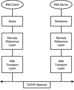
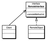
| Enterprise applications are, by definition, logically distributed. The term distributed processing refers to an application that is made up of multiple processes working together. The processes may be running on separate hosts on a network or on the same host. In a pure Java implementation, Distributed Processing refers to classes running in different Java Virtual Machines (JVMs) working in cooperation. This is where Remote Method Invocation (RMI) comes into play. RMI provides the mechanism for a Java class to call methods on an object running in a separate Java Virtual Machine. This is actually the underlying core technology for Enterprise Java Beans (EJBs). At the heart of a J2EE application is an EJB that implements the business logic for the application. Enterprise Java Beans provide a remote interface that acts as their thin client to the bean. Typically, a servlet uses the remote interface to communicate with the EJB. The details of the RMI structure and how it is used with J2EE are covered in this chapter. It is important for J2EE developers to understand these details to be able to build reliable, high-performance J2EE applications. The Java 2 Standard Edition comes with all the classes, interfaces, and tools necessary to create distributed applications that use RMI. By using them, you can learn the technology and develop working prototypes or applications with moderate performance requirements. The performance and reliability requirements of J2EE applications go beyond the basic capabilities of the standard edition RMI. The WebLogic RMI provides enhanced capabilities that address your needs as a J2EE developer. This chapter covers the standard edition RMI, as well as the enhancements offered by the WebLogic RMI. From this background knowledge of the underlying architecture, you will have a much better understanding of the roles played by each component in a distributed application that uses RMI. The communication between the processes is ultimately a data stream over a TCP/IP socket. The socket provides the communication path for the client/server protocol. The server listens to a specific TCP/IP port and accepts connections on that port. The client connects to the server by specifying the hostname and port number of the socket server. When the socket is connected, it acts as a bidirectional pipe. Any data written by the client is read by the server, and vice versa. Following these requirements, RMI provides a server, client, and data stream that is passed across the socket. Figure 12.1 shows a graphical representation of the RMI architecture. The server is the RMI remote object, and the client is the application that uses the remote interface. The data stream is automatically generated for you through the process of "marshalling" the arguments and return values of the remote method calls. The process of converting the parameters and return values of a remote method call into a data stream is referred to as marshalling . This process will be described in detail in the "RMI Design Model" section later in this chapter. Figure 12.1. The RMI client and server communicate through a layered architecture over a TCP/IP network connection. The RMI Design ModelThe structure of a distributed application that uses RMI follows a common design pattern. RMI provides the technology to create a thin client that communicates with the more complex remote object. This is identical to the "Proxy" structural design pattern which is a placeholder class for a more complex class. Please refer to Chapter 6, "Transitioning from Software Design to J2EE Technology Components and Services" for a complete description of the "Gang-of-Four" Design Patterns. A remote interface defines the API, a remote object implements the interface, and a client uses the interface, as shown in Figure 12.2. Figure 12.2. The RMI design model consists of a client that uses a remote interface and a RMI server that implements the interface. These three components are written by the application programmer. This leaves two questions: How does the client find the remote object, and how is the remote method actually "called" across the network? As you may have suspected, to discover the location of the remote object, you use a naming servicein this case, the RMI registry. The RMI registry is a server process that performs the naming service. RMI servers register their remote object and the clients retrieve the remote object through the RMI registry. The registry process is started by running the command rmiregistry . The API for the RMI registry is nearly identical to the naming context for JNDI. Chapter 14, "Locating Named Services Through JNDI," is devoted to the Java Naming and Directory Interface (JNDI). There, you will find a comparison between the RMI registry and JNDI. In a J2EE application, JNDI can be used to completely replace the RMI registry. The remote method call is performed through two generated classes called the stub and the skeleton . These classes marshal the parameters and return value across the network connection. Again, the term marshal means to serialize the parameters so they can be written to the remote object that, in turn , deserializes them back into objects. The stub and skeleton were shown in Figure 12.1 as the layer in the RMI architecture which the client and server directly communicate. The return value is also processed by marshalling in the same manner. This concept is built into the Java language through the Serializable interface. Therefore, the only restriction with remote methods is that all the parameters and the return value must be serializable. The client and remote object do not need to know anything about the stub or skeleton. As far as the client knows , it is calling the method directly. The descriptions of the remote interface, remote object, and RMI client application in the following sections show that they are implemented as normal Java interfaces and classes. The standard rules for Java packages and access modifiers apply. By following these rules, you can implement the remote object with public or package scope. You need to pay particular attention to the Java RMI interfaces and classes that are extended and used by your implementation. RMI Package NamesThe classes and interfaces that compose the API for RMI, shown in Table 12.1, are released in packages that organize common functionality. All packages from the JavaSoft implementation begin with java.rmi . The corresponding package for the WebLogic implementation begins with weblogic.rmi . WebLogic offers features and enhancements that are discussed in this chapter. However, for the most part, only the import statements need to be changed when a JavaSoft RMI implementation is being migrated to a WebLogic implementation. Table 12.1. The Classes and Interfaces for RMI Are Organized into Five Java Packages
Creating an RMI ApplicationReferring to Figure 12.2, the basic structure of an RMI application consists of a remote interface, a remote object, and a client. The remote interface exposes the public API of the remote object. The remote object implements the remote interface and the client uses the remote interface. Therefore, the steps to create an RMI application are:
|
EAN: 2147483647
Pages: 360
- Structures, Processes and Relational Mechanisms for IT Governance
- Linking the IT Balanced Scorecard to the Business Objectives at a Major Canadian Financial Group
- Measuring ROI in E-Commerce Applications: Analysis to Action
- Governance in IT Outsourcing Partnerships
- Governance Structures for IT in the Health Care Industry
- Chapter IV How Consumers Think About Interactive Aspects of Web Advertising
- Chapter V Consumer Complaint Behavior in the Online Environment
- Chapter VI Web Site Quality and Usability in E-Commerce
- Chapter IX Extrinsic Plus Intrinsic Human Factors Influencing the Web Usage
- Chapter XV Customer Trust in Online Commerce

