Designing Your Application
| Typically, the first step in designing an application is for the application architect to define the components that make up the application, the communication between those components, and their settings and constraints. The application diagram directly supports this activity. Doing this step first in the process allows the application architect to lay out the components of the system and have those elements verified for deployment by a logical datacenter diagram. Once verified, these components can then generate stub projects and code for the solution. This will give the development team a head start. The following lists the logical order of using the diagrams in Visual Studio 2005 to build a new application:
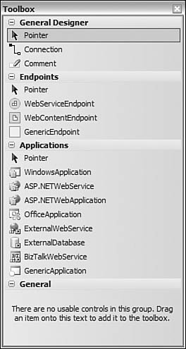
We will walk through each of these steps throughout the rest of this chapter. Our examples will follow the design of the application begun in Chapter 20, "Work Item Tracking." Recall that this application represents a customer management system for an existing e-commerce application. Tip Visual Studio will generate the model of your application if you add an application diagram to the existing application. This can be a great way to understand the relationship between components of an application. It is also a great place to start when you're working with an existing application to extend its functionality. In fact, all application models are synchronized with the solution that contains them. This ensures the models stay in step with the code base. Working with the Application DiagramYou've seen how to add an application diagram to a solution. Now you're ready to look at the application diagram in greater detail. Figure 21.3 shows an open application diagram in the IDE using the Application Designer toolset. Figure 21.3. The Application Designer.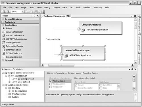 The four main parts of the Application Designer are the diagram itself, the Toolbox items, the Settings and Constraints window, and the Diagram menu. These four items allow you to design the details of your application. Now let's look at each of these items in more detail. The Diagram MenuThe Diagram menu is active only when you have an architectural diagram loaded in the active window. The contents of the menu change depending on what type of diagram you have loaded. In fact, even the application Diagram menu changes depending on what is selected in the actual diagram. Figure 21.4 shows an example of this menu for an application diagram with a web service application selected. Figure 21.4. The Diagram menu.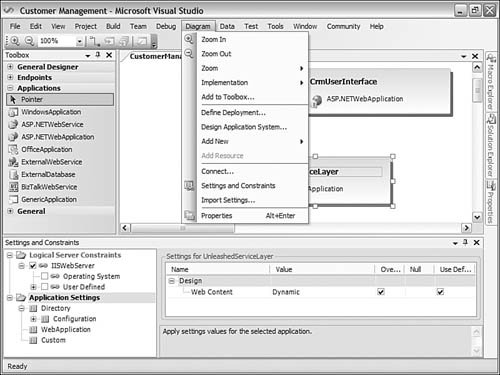 Some key features worth discussing are that the menu provides access to include Define Deployment, Design Application System, and Add to Toolbox. The Define Deployment menu item enables you to select the deployment details of the application. We will cover this item later when we discuss the deployment diagram. The Design Application System menu item allows you to create a system from components of your application. We'll cover this item in the next section. Finally, the Add to Toolbox menu item allows you to take an existing application, endpoint, or group of applications and create a reusable Toolbox item from it. This capability can be useful if you are consistently reusing an element across diagrams. Application Designer ToolboxThe Application Designer Toolbox provides access to the items that can be added to the application diagram. These items are grouped into three sections: General Designer, Endpoints, and Applications. The General Designer section contains elements that are common to many of the architect designers. The Endpoints section groups the endpoint connections that define the communication between applications. Finally, the Applications section groups the various applications that can be defined on the diagram. Figure 21.5 shows a visual representation of this Toolbox. Figure 21.5. The Application Designer Toolbox. For the most part, these Toolbox items are aptly named, and you should have no problem using them. We will cover adding applications and using the endpoints in the coming section. Note The applications in the Toolbox are either clients, web services, or databases. There is no support for adding frameworks or class libraries to the Application Designer. These items are not part of the Application Designer by design. The Application DiagramThe application diagram represents the canvas for the application architect. It is here that you drag applications from the Toolbox and connect them together to form a solution. Figure 21.6 shows an application diagram in progress. Figure 21.6. The application diagram.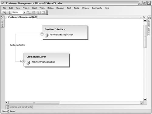 There are two ASP.NET web application items on the diagram. The top one, CrmUserInterface, represents the web-based user interface screens for the customer management sample application. The one below that, CrmServiceLayer, is a web service for the CustomerProfile service. Notice that once they are placed on the diagram it is difficult to distinguish between a web application and web service; this is by design because either application could contain both .aspx and .asmx files. There is also an arrow that connects the two applications. This arrow is a Connection item; it is used to connect endpoints of an application. Notice that each application has an associated endpoint. Each endpoint is a web service endpoint. The CrmUserInterface endpoint has a hollow or white background, indicating it is the client endpoint. The CrmServiceLayer endpoint is solid to indicate it represents the server. The arrow also indicates the direction of caller (client) to server. Finally, the arrow contains a decorator or label. This label indicates the web service that connects the two applications (CustomerProfile). This relationship will become a web reference upon implementation. Now let's look at adding a couple of new applications to the diagram and connecting them. Adding ApplicationsYou add applications to the diagram through drag-and-drop. For the example, you will add an external database to which the service layer can connect. This external database belongs to the existing e-commerce application that the CRM application extends. You will also add a Windows user interface to allow the sales and marketing team to do their data analysis work. Figure 21.7 shows the results of this work. Figure 21.7. Additional applications added to the model.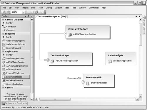 Connecting ApplicationsNow you're ready to add endpoints to the applications and connect them. The Toolbox shows three endpoints, but there is actually a fourth one: DatabaseServerEndpoint. This endpoint exists on database applications by default. It can also be dragged to connecting applications. The following list describes the possible endpoints for connecting applications in the diagram:
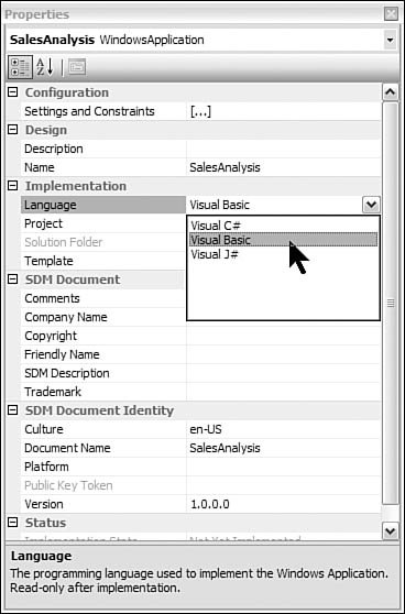
You will use these endpoints to connect applications. First, the SalesAnalysis Windows client application will need to connect to the CrmServiceLayer through a web service endpoint. Next, the CrmServiceLayer will require a connection to the EcommerceDB database. First, you add all the endpoints to the various applications. Next, to connect the endpoints, you can use the Connection item from the Toolbox. Alternatively, you can hold down the Alt key and select and drag the endpoint from one application to another. When you connect an application to a database application, Visual Studio presents you with the Connection Properties dialog box for establishing a connection to an actual database. You can cancel this step or define the actual connection details if they are set up. Figure 21.8 shows the applications connected. Notice the addition of a new web service layer: SalesAnalysisServices. The SalesAnalysis client application will connect to both the CRM layer and this newly defined layer. Also, notice the endpoint names. You can turn these labels off for each endpoint, show for each, or show for only one endpoint. The labels connecting to a web service represent the actual web service's name that is defined by the endpoint. Figure 21.8. The connected applications.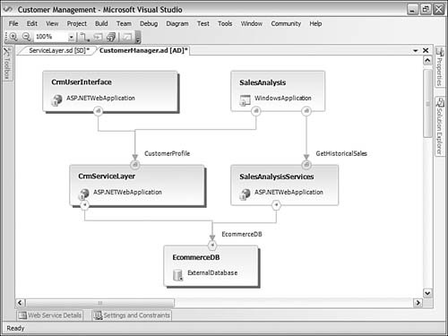 Application Settings and ConstraintsEach application on the diagram has a set of properties, settings, and constraints. This metadata helps further define how this application will be built and deployed. For example, suppose the web user interface must be deployed on a Windows 2003 Enterprise server that is running the .NET Framework version 2.0. To indicate this setting, you would select the CrmUserInterface application from the diagram, right-click, and choose Settings and Constraints. Visual Studio will present the related window in the IDE. Figure 21.9 shows this window and related setting. Figure 21.9. The Settings and Constraints window.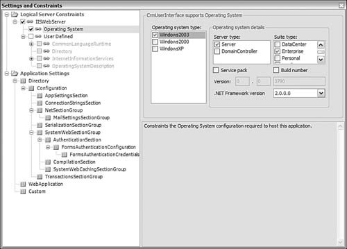 Notice that the Settings and Constraints window is split between Logical Server Constraints and Application Settings. The former represents the server on which the application will be deployed. Constraints entered here will be enforced when you try to deploy against a logical datacenter diagram. The Application Settings section is essentially the configuration file for the application. You can set all related settings here. These settings will be emitted when you implement the application diagram. On the right side of the screen, you modify the settings. Notice in the example the operating system, server type, suite type, and .NET Framework version have been selected. Application PropertiesYou can define additional implementation details about the application using the Properties window. Again, select an application from the diagram, right-click, and choose Properties. This will open the Properties window for the given application. Of course, the settings in this window are dependent on the type of application selected. As an example, assume that the development team for the SalesAnalysis Windows client application intends to work in Visual Basic. You can add this implementation detail in the Properties window. This setting will affect how Visual Studio emits the project when implementing the diagram. Figure 21.10 shows this process in action. Figure 21.10. The Application Properties window. Web Service SettingsRecall that each endpoint on a web service application represents an actual web service that will be implemented. The Application Designer allows you to indicate the implementation details of each of these web services. To add these details, you select a web service endpoint, right-click, and choose Define Operations from the context menu. Selecting this menu item will open the Web Service Details window. Figure 21.11 shows an example of this window along with the web service's Properties window. Figure 21.11. The Web Service Details window.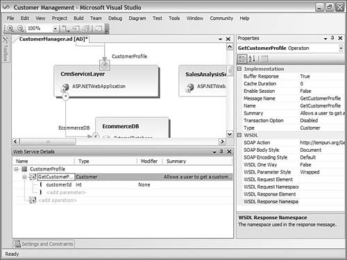 When defining web service details, you can add operations, set their return types, and indicate parameters. You can also define summary information that will be used for the XML documentation of the web service. |
EAN: 2147483647
Pages: 195