6.2 Availability within the Data Center
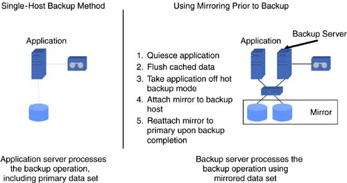
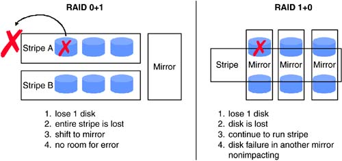
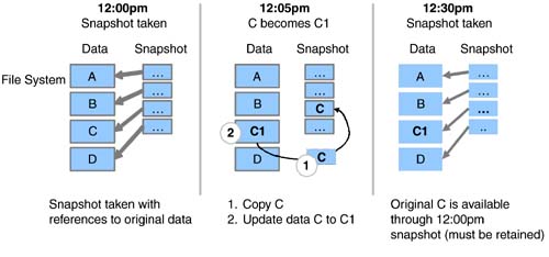
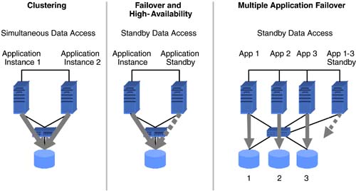
| In the beginning of this chapter, we touched briefly on various availability levels, ranging from simple backup and recovery to automated wide-area failover. These levels can be split into two categories. The first category outlined in this section addresses business continuity for applications and data within a data center. The second category, discussed in Section 6.3, addresses business continuity across geographically separate data centers. 6.2.1 Backup and RestoreRegularly scheduled data backup ensures a fundamental level of availability for applications. Backups can be used to retrieve an individual file or to rebuild entire servers and restore all the associated data. However, in most cases, restoring data from backups entails a certain amount of data loss. The amount of data lost depends on when the last successful backup was performed and the amount of data change since that backup. The time to restore depends on several factors, including, but not limited to, the amount of data to be restored, the data-backup policies employed, and the backup storage technology and methods used. Two basic backup types ”full and incremental ”determine how much data is backed up for a given operation. During a full backup, the entire data set is backed up, whereas an incremental backup stores only data that has changed since the last backup. Full backups obviously involve more time and media than incremental backups. However, restores , especially in the case of an entire system, will be faster with more frequent full backups. Backup policies, driven by availability requirements, dictate the schedules and the types of backup to be performed. Beyond the availability needs, some backup policies may also be determined based on legal requirements. For example, the legal department of a given company may determine that year-end financial data needs to be available for 10 years . This requirement, in turn , could translate to a backup policy that dictates full backups at the end of every year to be retained for a minimum of 10 years. Despite the emergence of several new data storage and retrieval technologies like CD-RW and DVD, tape still dominates as a backup storage medium. Tape drive speeds and tape storage capacities continue to increase. Tape-based technologies like Super DLT from Quantum; AIT-3 from Sony; and LTO from Hewlett-Packard, IBM, and Seagate enable between 100 to 110 GB of uncompressed data to be stored on a single tape while providing uncompressed transfer rates between 11 MBps and 15 MBps. A fair amount of business-critical data resides in databases, which in general yield good compression ratios. In these cases, it is not uncommon to see the tape storage capacity and drive transfer rates doubled . The increased tape-drive speeds raise backup performance, which puts more load on the IP and primary disk storage networks and also place increased loads on the processing resources of application and data servers. These factors, coupled with shrinking backup windows , have driven backup vendors to develop new backup methods. In the traditional backup method, data residing on an application host is backed up through that host. The host reads data from the attached storage into its memory. It then writes the data out to a locally attached tape drive or to another backup host over a network, which in turn writes it to an attached tape drive. In either case, the application host has to perform the reads and writes required for backup. Other methods of backup have been developed to offload the burden of backup processing from the application host. One such method, which has been around for a few years, starts with a mirrored copy of the data on the storage system. At the scheduled time for backup, the application is placed in backup mode, all outstanding writes in memory are flushed to disk, and a copy of the mirrored storage is detached. The application is then taken out of backup mode. The detached piece of the mirror represents a consistent point-in-time copy of the data. This mirror copy is mounted and backed up to a separate backup server. Once the backup is complete, the mirror copy is unmounted from the backup server, reattached, and resynchronized with its original copy on the application server. Placing the application in backup mode involves different operations for different applications. In some cases it is done by issuing application commands, while in other cases it could mean shutting down the application. The operation of detaching the mirror copy typically takes a very short amount of time. Examples of traditional backup, including mirroring examples, are shown in Figure 6-3. Figure 6-3. Single-host backup method and using mirroring prior to backup. The recent proliferation of SANs has led to the development of server-free backup technology. Using this method, backup data is moved from the application host's disk storage to a target tape device over the SAN. This data transfer does not have to go through the application host. At the time of backup, the application is placed in backup mode, and all outstanding writes are flushed to disk. Then, a point-in-time frozen-image copy of the data is made. Frozen images can be accomplished with storage array-based mirror copies, volume management “based mirror copies, or file system-based snapshots. Once a frozen-image copy is complete, the application leaves backup mode and then resumes normal operation. The next step performs a logical-to-physical mapping of the data on disk. Based on this map, a hardware device that can execute extended SCSI copy commands transfers the data to the target tape device. These hardware devices, sometimes referred to as third-party copy devices, include SCSI-to-FC bridges and tape libraries from various vendors. Regardless of the methods, media, and device technologies used, backup lays the foundation for the business continuance of applications. 6.2.2 Disk Redundancy: RAIDWhile backups provide an offline method for ensuring a fundamental level of availability, disk redundancy ensures a basic level of online availability. Redundant Array of Inexpensive Disks (RAID) concepts are typically used to achieve disk redundancy. The famous Berkeley paper entitled "A Case for Redundant Arrays of Inexpensive Disks," written by Patterson, Gibson, and Katz in 1987, proposed various levels of RAID for achieving tolerance to disk failures. Although several levels of RAID have been proposed beyond the levels 1 through 5 discussed in the original paper, the most common implementations include levels 0, 1, 3, 5, 0+1, and 1+0. Level 0, where data is striped across a number of disks, does not address redundancy but provides superior performance. Under RAID level 1, data on a particular disk is simply mirrored to one or more disks. In other words, the same data is written to multiple disks in parallel. If a disk becomes unavailable, data can be read from and written to the surviving mirrored disks. RAID levels 3 and 5 stripe data across a set of disks and also store parity information that can be used to rebuild data in case of a single disk failure in that set. Levels 3 and 5, however, cannot provide resiliency if more than one disk in a given set becomes unavailable. In terms of performance, write performance of RAID 1 is limited to the speed of the slowest mirrored disk. In most cases, disks with similar performance are used for mirroring, and hence RAID 1 does not typically impose any performance penalties. The parity calculation and, more importantly, the read-modify-write cycle involved with RAID levels 3 and 5 impose performance penalties for writes. However, since data is also striped in these levels, read performance will be better than that of a single disk. RAID levels 0+1 and 1+0 combine striping and mirroring to achieve levels of redundancy higher than provided by RAID 1, while also benefiting from the performance gains provided by striping. Under RAID 0+1, multiple disks are striped together to form a stripe set, and data is mirrored among two or more stripe sets. If a single disk in a stripe set fails, the entire stripe becomes unavailable. In the case of a RAID 0+1 configuration with two stripe sets A and B, failure of a single disk in stripe set A makes the entire stripe set unavailable, leaving stripe set B unprotected . A consequent disk failure in stripe set B would result in complete loss of access to all the associated data. In RAID 1+0, sets of two or more disks are mirrored to form mirror sets. These mirrored sets are then striped together. As long as each mirror set has at least a single disk available, multiple disk outages will not result in loss of access to the associated data. Hence, RAID 1+0 is considered to be more resilient than RAID 0+1. These distinctions are outlined in Figure 6-4. Figure 6-4. Comparing RAID 0+1 and 1+0. RAID is implemented either in storage array hardware using RAID controllers or through host-based volume management software. RAID controllers usually include NVRAM caches in addition to hardware required to implement the RAID logic, while host-based volume managers use host CPU and memory resources. From a performance perspective, RAID levels 3 and 5 implemented in array hardware are generally faster for write operations than is the software implementation. RAID levels 0, 1, 0+1, and 1+0 also benefit from the NVRAM write and read cache provided by arrays. Since we focus on business continuance in this chapter, we examine the availability implications of hardware and software RAID. Hardware RAID arrays available in various configurations fit a wide range of target markets. While the high-end arrays design out single points of failure, the low-end arrays could be designed with nonredundant components, such as a mirrored NVRAM write cache, or with single power connectors. Most of the high-end array vendors also offer "phone-home" support to proactively monitor and replace failed or failing components before a consequent failure causes a storage disruption. For applications where the cost associated with high-end RAID arrays cannot be justified, host-based volume managers, using relatively inexpensive low-end arrays or even JBODs (just a bunch of disks), can fulfill availability requirements. Even though high-end arrays include fully redundant components, certain system architectures require that for a given host, data be mirrored for additional redundancy or striped for performance across two high-end arrays. In order to accommodate such architectures, host-based volume managers operate on top of the arrays. Even in cases where a single, fully redundant, high-end array will suffice, a host-based volume manager is also commonly deployed. Reasons for this include administration of logical volumes and volume groups instead of disparate devices with cryptic device names , and migration of data from a given storage array to another for upgrade or other purposes. A more important reason from an availability standpoint is that certain volume managers enable nondisruptive growth of file systems containing application data. Volume managers accomplish this by increasing the size of underlying volumes online using available LUNs provided by the storage array. Just as backup provides fundamental offline availability, disk redundancy, achieved by deploying RAID storage implemented in hardware, software, or both, provides basic online availability. 6.2.3 Quick Recovery File SystemsA majority of business-critical applications today run on multiple-CPU servers. In the event of CPU failure, most operating systems crash the server and reboot around the failed CPU. In other words, the reboot process fences off the failed CPU. Obviously, during the reboot process, the application running on this server is unavailable. A portion of the reboot process involves checking the file system for consistency. Hence, the time interval for which the application remains unavailable directly depends on the amount of time taken to complete checking all the necessary file systems. Certain file systems, such as the traditional UNIX file system (UFS), have to perform a complete file system structure check and fix any discovered inconsistencies to recover from a file system failure. For applications with large amounts of data, this could take a significant amount of time. Several file systems available today address this issue by providing journaled or logging file systems. These file systems record structural changes to the file system in a log or journal. During recovery, the file system consistency-check utility does not have to scan the entire file system, but instead scans only the log and invalidates or completes file system transactions that were active at the time of file system failure. This feature greatly reduces the amount of time required for an application to recover from a system crash and reboot. Bear in mind that even with journaled file systems, certain crash situations could still require a full file system check. Another related feature, available in some products, is the ability to perform checks for multiple file systems in parallel. Applications with a large number of file systems benefit from this time-saving feature. Journaled file systems, preferably with a parallel file system check feature, reduce application downtime by enabling quick recovery after a crash. 6.2.4 Point-in-Time CopiesLogical data corruption, especially in the case of databases, is one of the more common causes of application downtime. Corruption results from application data being lost or altered by sources other than the application, without the application's knowledge. Some causes for data corruption include faulty hardware, bugs in software, and sometimes user or administrator error. Disk mirroring does not help in this scenario, since logical corruption typically is propagated to all the mirror copies. One way to recover applications from logical data corruption is to restore data from backup tapes. However, this can be a time- intensive method, depending on the amount of data that needs to be restored and the available hardware. In most cases the entire application may have to be taken offline during the restore process. For database administrators, data corruption resulting from partial data block writes, out-of-order transaction commits, accidentally deleted rows, and dropped tables cause major concern. Maintaining a standby database on a separate database server, periodically refreshed by applying transaction logs shipped from the primary database, helps database administrators recover quickly from logical corruption. The standby database represents a point-in-time copy of the primary database. If logical corruption occurs on the primary and is detected in the period between log updates to the standby database, the standby database is quickly promoted to assume the primary role. This dramatically reduces database downtime. Apart from serving recovery purposes, standby databases offload backup and reporting functions from the primary. Several file systems on the market today provide a snapshot feature allowing an administrator to maintain point-in-time copies. A snapshot represents a frozen image of the file system at a particular point in time. Applications can recover from logical data corruption in a relatively quick manner by restoring data from earlier snapshots or even rolling back all the changes made to a file system since the last consistent snapshot. Most file system snapshot implementations use a copy-on-write mechanism, which does not require twice the allocation of storage space per snapshot. This technique keeps copies of changed file system blocks only since the snapshot was taken. However, maintaining copies of updated and deleted blocks does introduce additional I/O overhead for write operations on the system. It is also possible to keep multiple snapshots for a given file system. The amount of additional storage space required depends on the amount of data change in the file system since the earliest snapshot. Figure 6-5 shows a sample snapshot method. Figure 6-5. An example point-in-time snapshot copy method. Yet another method of recovering from logical data corruption is made possible by disk mirrors. Disk mirroring enables point-in-time copies of data at the logical data volume and disk device level. Most high-end storage arrays and certain volume management products provide tools that enable detaching a copy from the mirror set. This copy represents a point-in-time image of block data on storage devices. Unlike file system snapshots, a na ve implementation of disk mirrors can require twice the amount of storage for each mirror copy. Hence, in most cases, it is impractical from a cost perspective to keep more than two copies. Since data updates to the primary mirror are not reflected in the detached copies, they have to be periodically synchronized to keep the point-in-time images from lagging too far behind the primary. Data corruption occurring and detected during the synchronization process corrupts all copies being synchronized. Synchronizing two copies with the primary mirror at separate times provides protection against this possibility. Recovery from data corruption involves shutting down the application, unmounting file systems from the corrupt device set, mounting file systems on point-in-time mirror copies, and restarting the applications. The mounting and unmounting of file systems is skipped for certain applications, such as databases, running on raw volumes or devices. In a SAN and in other shared storage environments, the mirror copies can be dissociated from the primary application host and made available to a secondary host for backups and other off-host processing functions. Point-in-time data images provided through database copies, file system snapshots, volume manager mirror copies, and disk device mirror copies enable quick application recovery from logical data corruption. 6.2.5 High Availability and ClusteringApplication and data unavailability resulting from host failure can be addressed with database servers (in case of database host failure) and point-in-time mirror copies attached to secondary hosts. However, detecting server failure, activating secondary systems, and pointing users or applications to these secondary hosts requires manual intervention. In most cases these tasks can be performed by a few skilled individuals who may not be accessible at all times. High-availability and clustering solutions automate the detection of application service disruption due to host-related failures and their resumption on a designated secondary host. This failover process occurs transparently to the end user. Neither clustering nor high availability provide protection from logical data corruption. Very often, the term clustering is used when referring to high-availability solutions. However, an important distinction between the two exists, especially from an applications and data perspective. High-performance clusters are used by applications that run on many independent servers with little or no sharing of data. In storage, clustering implies that instances of an application running on multiple hosts have simultaneous read and write access to the same data set. If a host fails, users or other applications connected to that host switch to a different cluster host, and application service resumes. Oracle Parallel Sever and its successor Real Application Clusters (RAC) are examples of clustered databases. With high availability, only one instance of an application accesses the data at any given time. When a host fails, another designated host takes control of the data resources and performs the necessary volume, file system, and application startup functions. As a result, a noticeable amount of time can elapse when the application service will be unavailable. Application downtime depends, to a large extent, on the amount of time required for application recovery. Applications such as Network File System (NFS) can be failed over in a relatively short period of time with minimal or no disruption to end users. However, recovery times of over 15 minutes are not uncommon for fairly active OLTP databases. Clustering solutions generally provide faster failover than do their high-availability counterparts, but they are usually more complex to implement and administer. Figure 6-6 shows examples of clustering and high-availability solutions. Figure 6-6. Examples of clustering and high-availability storage networking solutions. Both high-availability and clustering solutions share similar hardware configuration requirements. Both have no single point of hardware failure. A typical hardware configuration for a given application consists of two host machines, mirrored data storage accessible to both hosts, a minimum of two redundant private heartbeat networks to monitor the health of application and hardware components, and at least one public network interface for user access per host. In the case of clustering, both hosts generally have active instances of an application, while under a high-availability scenario, the application could be active on one host while the other host "stands by," monitoring the active host and ready to take over in case of a failure. In an "active-active"high-availability configuration, individual hosts run different applications and each host acts as a failover machine for the other's application. If a host fails, its application and data are taken over and services are resumed on the surviving host, and the application already running on that host continues without interruption. Hence, when implementing an active-active high-availability solution, adequate resources should be allocated on each machine to handle the additional load, or the expectation of degraded performance in case of a failover should be set. Clustering and failover mechanisms can also be used for offensive storage strategies, such as scheduling hardware and software upgrades. During regularly scheduled maintenance, high-availability configurations and software facilitate simpler upgrades. While one host is acting as a standby, the other undergoes the upgrade, and vice versa. SANs make it possible for multiple host systems and pools of storage to be interconnected . It is thus possible for a host to have access to the storage being used by other hosts in the SAN. In this environment, economies of scale can be leveraged when implementing high-availability solutions for multiple application hosts. A single, appropriately configured host could act as a standby machine for multiple application hosts, thus avoiding the need for a dedicated standby machine for each application host. Of course, the implicit assumptions are that not more than one host will fail at any given time, and if more than one host does fail, the standby host has adequate resources to handle the load. Clustering and high-availability solutions reduce application downtime by providing automated and transparent application service resumption in the event of an outage of the underlying host machine. These solutions also enable offensive strategies such as reducing the cost of maintenance and upgrades. |
EAN: 2147483647
Pages: 108
- Key #1: Delight Your Customers with Speed and Quality
- Key #2: Improve Your Processes
- Key #4: Base Decisions on Data and Facts
- Making Improvements That Last: An Illustrated Guide to DMAIC and the Lean Six Sigma Toolkit
- The Experience of Making Improvements: What Its Like to Work on Lean Six Sigma Projects