Creating a Dimension Style
Dimension styles are similar to text styles. They determine the look of your dimensions as well as the size of dimensioning features, such as the dimension text and arrows. You might set up a dimension style to have special types of arrows, for instance, or to position the dimension text above or in line with the dimension line. Dimension styles also make your work easier by enabling you to store and duplicate your most common dimension settings.
AutoCAD gives you one of two default dimension styles, ISO-25 or Standard, depending on whether you use the metric or Imperial (also called English) measurement system. You will probably add many other styles to suit the type of drawings you are creating. You can also create variations of a general style for those situations that call for only minor changes in the dimension's appearance.
In this first section you'll learn how to set up your own dimension style based on the Standard dimension style (see Figure 9.2). For metric users, the settings will be different, but the overall methods will be the same.
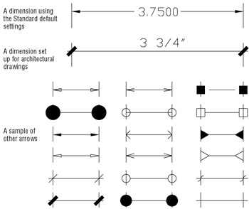
Figure 9.2: AutoCAD's Standard dimension style compared with an architectural-style dimension
Follow these steps to create a dimension style:
-
On the CD Open the Unit file you edited in the preceding chapter. If you didn't create one, use the 09a-unit.dwg file on the companion CD and rename it Unit.dwg . Metric users should open 09a-unit-metric.dwg and rename it Unit-metric.dwg .
-
Issue Zoom All to display the entire floor plan.
-
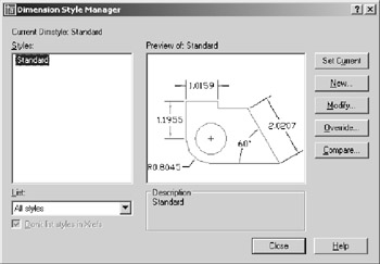
Choose Format Dimension Style or type D
 at the command prompt to open the Dimension Style Manager dialog box.
 -
Select Standard from the Styles list box. Metric users should select ISO-25.
-
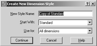
Click New to open the Create New Dimension Style dialog box.
-
With the Copy Of Standard or ISO-25 name highlighted in the New Style Name input box, enter My Architectural .
-
Click Continue to open the detailed New Dimension Style dialog box.
You've just created a dimension style called My Architectural, but at this point it is identical to the Standard style on which it is based. Nothing has happened to the Standard style; it is still available if you need to use it.
Setting Up the Primary Unit Style
Now you need to set up your new dimension style so that it conforms to the U.S. architectural style of dimensioning. Let's start by changing the unit style for the dimension text. Just as you changed the overall unit style of AutoCAD to a feet-and-inches style for your bath drawing in Chapter 3, you must do the same for your dimension styles. Setting the overall unit style does not automatically set the dimension unit style. Follow these steps:
-
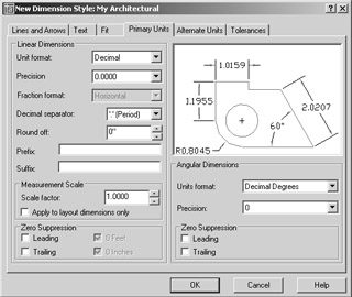
In the New Dimension Style dialog box, click the Primary Units tab.
-
In the Linear Dimensions group , open the Unit Format drop-down list and choose Architectural. Notice that this drop-down list contains the same unit styles as the main Units dialog box (choose Format Units). Metric users can skip this option.
Tip You might notice the Decimal Separator option a few settings below the Unit Format option. The Decimal Separator option lets you choose between a period and a comma for decimal points. Metric users often use the comma for a decimal point, and U.S. users will use a period. This option doesn't have any meaning for feet-and-inch measurements, so it is dimmed when the Architectural unit format is selected.
-
Select 0 ¢ -0 ¼ ² from the Precision drop-down list, just below the Unit Format list. Metric users should select 0.00. The Precision option enables you to set the level of precision that is displayed in the dimension text. It doesn't limit the precision of AutoCAD's drawing database. This value is used to limit only the display of dimension text values.
Tip Every dimension style setting has an equivalent system variable. See Appendix C for more on system variables that are directly associated with dimensions.
-
Just below the Precision drop-down list, open the Fraction Format drop-down list and select Diagonal. Notice what happens to the graphic. The fractional dimensions change to show you how your dimension text will look. Metric users can skip this step, because it isn't available when the Decimal unit format is selected.
-
In the Zero Suppression group in the lower-left corner, click 0 Inches to turn off this check box. If you leave it turned on, indications of 0 inches will be omitted from the dimension text. (In architectural drawings, 0 inches are shown as in this dimension: 12 ¢ -0 ² .) Metric users can ignore this option.
If you use the Imperial measurement system, you have set up My Architectural's dimension unit style to show dimensions in feet and inches, the standard method for U.S. construction documents. Metric users have just changed the Precision value and kept the decimal unit system.
Setting the Height for Dimension Text
Along with the unit style, you will want to adjust the size of the dimension text. The Text tab of the New Dimension Style dialog box lets you set a variety of text options, including text location relative to the dimension line, style, and height.
Follow these steps to set the height of your dimension text:
-
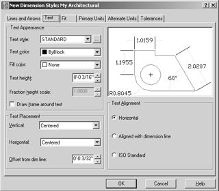
Click the Text tab to display the text options.
-
Highlight the contents of the Text Height input box.
-
Type 1 / 8
to make the text height 1 / 8 ² high. Metric users should enter 0.3 for the text height.
Unlike the text you created in Chapter 8, you specify the text height by its final plot size. You then specify an overall dimension scale factor that affects the sizing of all the dimensioning settings such as text and arrows.
If you want to use a specific text style for your dimensions, select a text style in the Text Style drop-down list in the Text tab. If the style you select happens to have a height specification greater than 0, that height will override any text height settings you enter in the Text tab.
Setting the Location and Orientation of Dimension Text
AutoCAD's default setting for the placement of dimension text puts the text in line with the dimension line, as shown in the example at the top of Figure 9.2, earlier in this chapter. However, you want the new Architectural style to put the text above the dimension line, as is done in the center of Figure 9.2. To do that, you will use the Text Placement and Text Alignment options in the Text tab of the New Dimension Style dialog box:
-
In the Text Alignment group in the lower-right corner of the dialog box, click the Aligned With Dimension Line radio button.
-
In the Text Placement group, open the Vertical drop-down list and select Above. Notice how the appearance of the sample image changes to show you how your new settings will look.
-
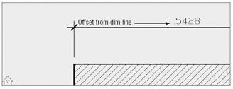
Again in the Text Placement group, change the Offset From Dim Line value to 1 / 16 . This setting controls the size of the gap between the dimension line and the dimension text.
Each time you change a setting, you get immediate feedback on how your changes will affect your dimension style by watching the graphic.
| Tip | Metric users might not need to change these settings, depending on your preference for dimension styles. |
Choosing an Arrow Style and Setting the Dimension Scale
Next , you want to specify a different type of arrow for your new dimension style. For linear dimensions in architectural drawings, a diagonal line, or tick mark, is typically used, rather than an arrow.
In addition, you want to set the scale for the graphical components of the dimension, such as the arrows and text. Recall from Chapter 8 that text must be scaled up in size in order to appear at the proper size in the final output of the drawing. Dimensions, too, must be scaled so they look correct when the drawing is plotted. The arrows are controlled by settings in the Lines And Arrows tab, and the overall scale of the dimension style is set in the Fit tab.
Here are the steps for specifying the arrow type and scale:
-
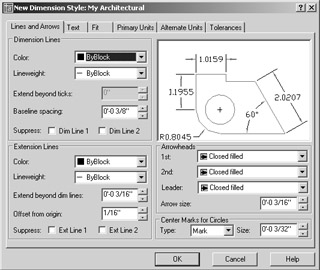
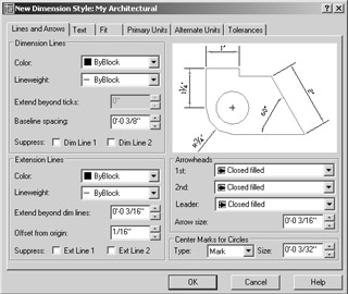
Click the Lines And Arrows tab to display the options for controlling the arrow style and dimension line extensions.
-
In the Arrowheads group, open the 1st drop-down list and choose Architectural Tick. The graphic next to the arrowhead name shows you what the arrowhead looks like.
Tip See Appendix C for details on how you can create your own arrowheads. Also, AutoCAD lets you set up a separate arrow style for leaders .
-
In the Arrowheads group, change the Arrow Size setting to 1 / 8 . Metric users should enter .3 .
-
In the Dimension Lines group, highlight the value in the Extend Beyond Ticks input box and enter 1 / 16 . (Metric users should enter 0.15 .) This causes the dimension lines to extend past the tick arrows. This is a standard graphic practice used for dimensioning linear dimensions in architectural plans.
-
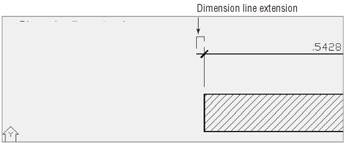
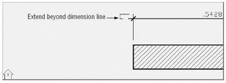
In the Extension Lines group, change the Extend Beyond Dim Lines setting to 1 / 8 . Metric users should change this to .3. This setting determines the distance that the extension line extends past the dimension line.
-
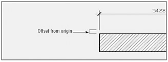
Again in the Extension Lines group, change the Offset From Origin setting to 1 / 8 . Metric users should change this to .3. This sets the distance from the point being dimensioned to the beginning of the dimension extension line.
-
Click the Fit tab of the New Dimension Style dialog box to display the options for overall dimension scale and miscellaneous settings.
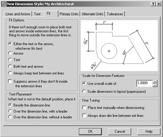
-
In the Scale For Dimension Features group, select the Use Overall Scale Of radio button.
-
Double-click the list box just to the right of the Use Overall Scale Of radio button and enter 48 . This is the scale factor for a ¼ ² scale drawing. Metric users should enter 50 .
All the values that you enter for the various options in the New Dimension Style dialog box will be multiplied by this value to obtain the final size of the dimension components. For example, the text height you entered earlier, ¼ ² , will be multiplied by 48 for a dimension text height of 6 ² . For metric users, the text height of 0.3 will be multiplied by 50 for a text height of 15 cm.
| Tip | If you use the Scale Dimensions To Layout (Paperspace) option in the Scale For Dimension Features group of the Fit tab, AutoCAD uses the layout viewport scale to size the dimension components. See Chapter 7 for more information on viewport scale settings. This can be useful if you have a drawing that you want to print at multiple scales . |
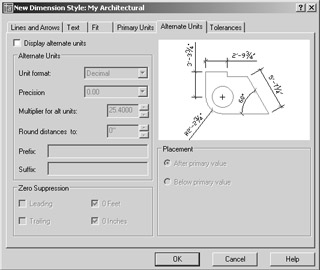
Setting Up Alternate Units
You can use the Alternate Units tab of the New Dimension Style dialog box to set up AutoCAD to display a second dimension in centimeters or millimeters. Likewise, if you are a metric user , you can set up a second dimension to display feet and inches. The following exercise shows you how to set up alternate dimensions. You don't have to do this exercise now. It's here for your information. If you like, come back later and try it out to see how it affects your dimensions. You can pick up the tutorial in the next section, " Setting the Current Dimension Style."
| Tip | If you decide later that you do not want the alternate units to be displayed, you can turn them off by returning to this dialog box and removing the checkmark in the Display Alternate Units check box. |
Here are the steps for setting up alternate dimensions:
-
In the New Dimension Style dialog box, click the Alternate Units tab.
-
Click the Display Alternate Units check box. The options in the tab become available for your input.
-
Select the appropriate option from the Unit Format drop-down list. U.S. users should select Decimal to show metric alternate units. Metric users should select Architectural.
-
Select an appropriate precision value from the Precision drop-down list.
-
Enter a scale factor for your alternate dimension in the Multiplier For Alt Units input box. For U.S. users, the default value is 25.4. This value converts feet-and-inch dimensions to millimeters. In our metric examples, you've been using centimeters, so change this setting to 2.54. Metric users should enter 0.3937 to convert centimeters to feet and inches.
-
In the Placement group, select where you would like the alternate dimension to appear in relation to the main dimension.
-
Click OK to close the New Dimension Style dialog box. The Dimension Style Manager dialog box reappears.
Setting the Current Dimension Style
Before you can begin to use your new dimension style, you must make it the current default.
-
Click My Architectural in the Styles list box in the Dimension Style Manager dialog box.
-
Click the Set Current button in the far-right side of the dialog box.
-
Click Close to exit the Dimension Style Manager dialog box.
You're now ready to use your new dimension style. In the next set of exercises, you will be using the My Architectural style you just created. To switch to another style, open the Dimension Style Manager dialog box again, select the style you want from the Styles list, and click Set Current, just as you did in the previous exercise.
| |
Every now and then, you'll need to dimension a small gap or a small width of an object that won't allow dimension text to fit. The Fit tab offers a few other settings that control how dimensions act when the extension lines are too close. The Text Placement group offers three options to place the text in tight situations:
Beside The Dimension Line Places text next to the extension line but close to the dimension line. You'll see how this affects your dimension later.
Over The Dimension Line, With A Leader Places the dimension text farther from the dimension line and includes an arrow or leader from the dimension line to the text.
Over The Dimension Line, Without A Leader Does the same as the previous setting, but does not include the leader.
The options in the Fit Options group let you control how text and arrows are placed when there isn't enough room for both of them between the extension lines.
| |
Modifying a Dimension Style
To modify an existing dimension style, open the Dimension Style Manager dialog box, highlight the style you want to edit, and then click Modify to open the Modify Dimension Style dialog box. This is virtually identical to the New Dimension Style dialog box you've been working with. You can then make changes to the different components of the selected dimension style. When you've finished making changes and closed both dialog boxes, all the dimensions associated with the edited style will update automatically in your drawing. For example, if you decide you need to change the dimension scale of a style, you can open the Modify Dimension Style dialog box and change the Scale value in the Fit tab.
This section introduces you to the various settings that let you set the appearance of a dimension style. This section doesn't discuss every option, so if you want to learn more about the other dimension style options, consult Appendix B. There you'll find descriptions of all the items in the New Dimension Style and Modify Dimension Style dialog box, plus reference material covering the system variables associated with each option.
| Tip | If your application is strictly architectural, you might want to make these same dimension style changes to the |
Acad.dwt template file or create a set of template files specifically for architectural drawings of differing scales.
EAN: 2147483647
Pages: 261