Adding Interior Walls and Cubicles
|
You can define interior rooms manually by dragging wall shapes into a building shell. The more automated method of defining rooms is to use room shapes, which define a space with four or more walls automatically. You can use room and space shapes together to display both square footage and dimensions in a building plan. For office designs, you can add prebuilt workstations with movable panel walls to show employee cubicles, which are available on the Cubicles stencil, as Figure 18-6 shows.
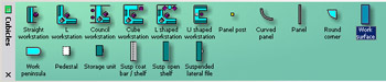
Figure 18-6: Visio Professional includes the Cubicles stencil, which features a variety of workstation and panel configurations that you can use to model the modern, movable office.
Calculating shape area and perimeter
Visio Professional can calculate the perimeter and area of any closed shape, which is a useful bit of information if you need to know the area of a room or the perimeter of an entire building for security equipment planning. To calculate these quantities, select Tools, Add- Ons, Visio Extras, Shape Area And Perimeter.
Designing Space with Room Shapes
Room shapes are a quick way to add four or more noncurving walls to a floor plan at once. When you select a room shape, Visio selects the entire room and displays the dimensions for all the walls, as Figure 18-7 shows. By contrast, if you add four wall shapes to a drawing to form a room, you can select each wall individually.
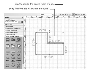
Figure 18-7: The “L” Room shape creates a room with six joined walls, which you can reposition. When you select a room shape, the walls’ dimensions are displayed.
When you drag a room shape onto the drawing page, Visio automatically adds joined walls with dimensions that appear only when the shape is selected. A room shape is actually a group, but you cannot subselect shapes in the group, such as individual walls. Control handles let you reposition the walls of the room. Because it’s a group, a room is easy to move on the drawing page—you can drag the entire room without worrying about its walls stretching out of shape. You can also add abutting walls to a room shape by gluing the walls’ endpoints to connection points on the room.
| Tip | If you aren’t sure how big your rooms will be or where you want them, use space shapes to rough out a floor plan. You can always convert them to rooms later. |
To create a room, follow these steps:
-
Drag the Room, “L” Room, or “T” Room shape onto the drawing page.
In Visio Standard, these shapes are on the Walls, Doors And Windows stencil. In Visio Professional, they’re on the Walls, Shell And Structure stencil.
-
To set the room’s size, select the shape, and then select Shape, Action, Properties.
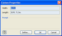
-
Type values in the Width and Length boxes, and then click OK.
Visio adjusts the size of the room. You can also drag a selection handle to size a room.
-
To move a wall, drag a control handle to the position you want. (When you point to the correct control handle, its ScreenTip will display “Reposition Walls.”)
Adding Interior Walls
You can define interior layouts by gluing wall shapes to other wall and room shapes. It’s easiest to add walls to a plan by gluing them to guides, as Figure 18-8 shows. The selection handles on a wall shape designate its interior edge, so it’s important to orient a wall shape correctly when adding it to a drawing. This behavior differs from that in Visio 2000. If you glue a wall “backward,” you can use the Flip Wall On Reference Line command on the shape’s shortcut menu to correct the wall’s orientation.
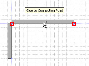
Figure 18-8: When selected, double-line walls display selection handles on their interior wall.
By default, walls look like double lines filled with gray, but you can display walls as single lines instead or as double lines with a reference line. Visio Professional also includes an Exterior Wall shape, which is thicker than the Wall shape. However, even if you’re working with the Visio Standard Wall shape, you can convert an exterior wall to an interior one and vice versa by changing the setting in the Exterior Wall field in the Custom Properties window.
When you glue wall shapes together, Visio joins their corners and T-joints so that walls are displayed correctly, as Figure 18-9 shows. Walls are smart in other ways as well. For example, you can quickly add a guide to any wall to help with alignment; when you select a wall shape, its dimensions are displayed.
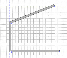
Figure 18-9: When you add individual wall shapes to a page, Visio joins their corners.
Follow these steps to add interior walls:
-
Drag the Wall shape from the stencil and position it inside the exterior structure. Repeat this process for all interior walls. In Visio Standard, the Wall shape is on the Walls, Doors And Windows stencil. In Visio Professional, the Wall shape is also on the Walls, Shell And Structure stencil.
-
To connect walls, drag an endpoint of one wall to another wall until the points turn red, indicating that the walls are glued.
-
To add a guide and glue the wall shape to it, right-click a wall, and then choose Add A Guide.
Tip To move the wall, drag the guide.
-
If the guide or the wall’s selection handles appear on the exterior of a room rather than its interior, right-click the wall shape, and then select Flip Wall On Reference Line.
Walls don’t connect correctly
For wall shapes to join properly, both snap and glue must be turned on. To see these settings, choose Tools, Snap & Glue. Under Currently Active, make sure that the Snap and Glue check boxes are selected. In both the Snap To and Glue To lists, make sure that the Shape Geometry and Connection Points options are selected.
Customizing the Appearance of Wall Shapes
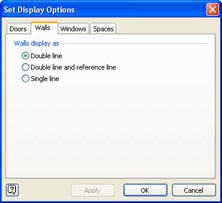
Walls are displayed as double lines with gray fill by default, but you can customize all the walls on a page to show single lines or double lines with a reference line, as Figure 18-10 shows. Display options for walls are a property of the drawing page, so when you choose an option, all the wall shapes (but not exterior wall shapes) on the current page are affected, but not shapes on other pages.
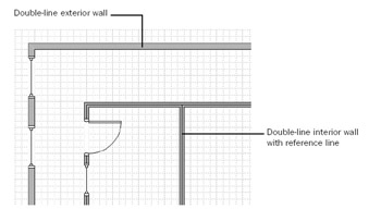
Figure 18-10: When you set the display options for walls, all the wall shapes on a page adopt the style. Exterior wall shapes are not affected.
To change how all walls on a page are displayed, follow these steps:
-
In a floor plan drawing, choose Plan, Set Display Options, and then click the Walls tab in the Set Display Options dialog box.
Note This command is not available in Visio Standard.
-
Choose an option, and then click OK to display all the wall shapes on the page with the new settings.
-
If your drawing has multiple pages and you want to use the same settings throughout the drawing, click the page tab near the bottom of the Visio window to display a page, and then repeat steps 1 and 2.
Creating a Ceiling Grid
If you’re using a floor plan to design what goes overhead, you need to show ceiling tiles and lighting panels and perhaps HVAC grills and diffusers. The Reflected Ceiling Plan template opens a combination of stencils for designing a ceiling grid, as Figure 18-11 shows. However, you can add the same information to any floor plan by opening just two stencils:
-
Electrical And Telecom
-
Registers, Grills And Diffusers
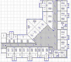
Figure 18-11: You can use the Reflected Ceiling Plan template to show a ceiling grid like this one, but you can also add ceiling tiles to any floor plan.
Visio doesn’t really have an automated way of creating a ceiling grid, which is why it doesn’t matter whether you use the Reflected Ceiling Plan template or not. You can easily start with any of the building plan templates to create a building shell and interior walls, and then add the ceiling grid. The basic technique goes like this: use the Line or Rectangle tool from the Standard toolbar to draw a ceiling grid.
You can save time by using the Array Shapes command to create multiple copies of ceiling panel shapes at regular, orthogonal intervals. In this case, draw one ceiling tile or a portion of the grid, select the shapes, and then choose Tools, Add-Ons, Visio Extras, Array Shapes to display the Array Shapes dialog box as Figure 18-12 shows.

Figure 18-12: The Array Shapes command in Visio Professional helps you create an evenly spaced grid of shapes, such as for a tiled ceiling.
The Layout options reflect the drawing scale and measurement units of the floor plan. Set Spacing to 0 to draw a grid. Or specify the distance between the edges of the tiles, and then select the Between Shape Edges option.
You can then add lighting panels, grills, diffusers, and other HVAC shapes to your ceiling plan. Drag lighting shapes from the Electrical And Telecom stencil and air device shapes from the Register, Grills And Diffusers stencil onto your drawing.
| Cross-Reference | For details about HVAC shapes, see “Adding Building Services,” page 532. |
|
EAN: 2147483647
Pages: 209