Example 5: Byte Read Request
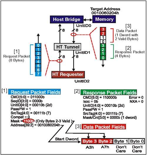
Example 5:Byte Read RequestProblem: Device 2 (UnitID2) in Figure 7-7 on page 167 targets main memory with a sized (byte) read of two bytes. Start dword address is 0010060204h; bytes of interest are at 0010060206h and 0010060207h. Figure 7-7. DMA Byte Read Targeting Main Memory Example 5: RdSized (Byte) Request Packet Setup(Refer to [1] in Figure 7-7 on page 167) Command[5:0] Field (Byte 0, Bit 5:0)This is the sized read (RdSized) command code. The option bits within this field are to be set up for byte transfer size, standard virtual channels, no coherency, and for relaxed ordering of response with respect to posted requests . So, response may pass posted requests (bit 3) bit is set; dword (bit 2), coherency (bit 0), and the Isoc (bit 1) bits are all disabled. For this example, field = 01 1000 b. SeqID[3:0] Field (Byte 0, Bit 7:6) and (Byte 1, Bit 6:5)This field is used to tag groups of requests that were issued as part of an ordered sequence. In this example, this request is not part of an ordered sequence. For this example, field = 0000b. UnitID[4:0] Field (Byte 1, Bits 4:0)For both upstream and downstream requests, this field is programmed with the UnitID of the requester. In this example, the request originates at Device 2 (UnitID2). For this example, field = 00010b. PassPW Bit Field (Byte 1, Bit 7)This bit is carried with read requests and isn't used until the response is generated. At that time the PassPW bit in the response will be set to match this bit. For this example, the response/data will allowed to pass posted requests in the same transaction stream. For this example, field = 1b. SrcTag[4:0] Field (Byte 2, Bits 4:0)This field tags the 32 outstanding non-posted transactions allowed to each UnitID. The code is assigned by requester from a pool of available tags. Assume that the tag for this read request is 7. For this example, field = 00111b. Compat Bit Field (Byte 2, Bit 5)Used by bridges to tag downstream requests targeting the compatibility chain (where subtractive decoder is found). Reserved field for upstream requests. For this example, field = 0b. Mask/Count[3:0] Field (Byte 2, Bits 7:6) and (Byte 3, Bits 1:0)For a sized (byte) read request, the value programmed into this field is a 4-bit mask used to indicate which of the four bytes in the target dword are of interest. This is comparable with the byte enable scheme used on buses such as PCI to get byte resolution on a dword-based bus. For this example, we are interested in accessing locations 0010060206h and 010060207h; both are contained in the dword located at start address 0010060204h. This means that the starting address will be 0010060204h and mask bits 2,3 will be enabled (set = 1), while mask bits 0,1 will be cleared (= 0). For this example, field = 1100b. Start Address Field (Bytes 4-7, Bit 7:0) and Byte 3, Bit 7:2)This field carries the 40-bit target start address. Again, the start address is always dword aligned and in sized (byte) reads the Mask/Count[3:0] bits are used to indicate the target bytes within the starting dword (see previous field). For this example, the target dword address for the request is in main memory. For this example, the 40-bit address = 0010060204h. Example 5: RdSized (Byte) Request, Sequence Of Events(Refer to Figure 7-7 on page 167)
Example 5: Byte Read Response Packet Setup(Refer to [2] in Figure 7-7 on page 167) When the Host Bridge has completed the dword read of memory (or a subset of a dword if the mask requires this), it prepares to return a Read response and the single dword to the original requester (UnitID2). The purpose of the response is to inform devices in the topology that read data follows and it identifies who the recipient should be. Many of the fields in the Host Bridge read response reflect the setting of similiar fields in the request which caused it. Command[5:0] Field (Byte 0, Bit 5:0)This is the command code for the Read Response. There are no option bits in this field. For this example, field = 110000b. Isoc Bit Field (Byte 0, Bit 7)This bit indicates whether this response should travel in the isochronous response virtual channel as it moves back to the original requester. Because the request which caused this response was not isochronous, this bit will not be set. For this example, field = 0b. UnitID[4:0] Field (Byte 1, Bits 4:0)Because this response is being issued by a Host Bridge and traveling downstream, the UnitID field carries the identity of the original requester (UnitID2). For this example, field = 00010b. Bridge Bit Field (Byte 1, Bit 6)Set by host bridges in responses they issue downstream (as in this example) so devices may distinguish upstream and downstream responses. For this example, field = 1b. PassPW Bit Field (Byte 1, Bit 7)This bit indicates whether this packet may pass packets in the posted request channel (for same transaction stream). Because the PassPW bit was set in the original request, it will also be set in the response. For this example, field = 1b. SrcTag[4:0] Field (Byte 2, Bits 4:0)The field is set to the same value as seen in the request. In our example, the Source Tag was 7. For this example, field = 00111b. Error Bit Field (Byte 2, Bit 5)In a read transaction, this bit in the response will be set to indicate an error was encountered in obtaining requested data. In this example, there were no errors. Refer to "Response Errors" on page 248 for a discussion of how response errors are handled in HyperTransport. For this example, field = 0b. Count[3:0] Field (Byte 2, Bits 7:6) and (Byte 3, Bits 1:0)For dword reads, the response count field is programmed to match the Mask/Count[3:0] field in the original request. For byte read transfers, the count is always set = 0 (1 dword). The count field in a read response informs tunnels and other devices in the path to the target how much data is to follow. For this example, field = 0000b. NXA Bit Field (Byte 3, Bit 5)This response bit is only valid if the Error bit (Byte 2, Bit 5) is set. IF NXA and Error are both set, the original request did not find the proper target at all, and the read response is being returned by a device at the end of the chain. If NXA is clear and Error set, then a read error occurred at the target device. For this example, field = 0b. Example 5: Sized (Byte) Read Data Packet(Refer to [3] in Figure 7-7 on page 167) The sized (byte) read request which caused this data packet to be sent specified a start address of 0010060204h. A single dword data packet is always returned for this type of request. The bytes within the dword data packet will be valid if their corresponding Mask/Count[3:0] bit was set =1; bytes within the target dword with a Mask/Count[3:0] bit not set will be driven to whatever value the agent sending the response decides. For our example, after the read only the two upper bytes (corresponding to addresses 0010060206h and 001060207h) are valid. (Two data values are arbitrary).
Example 5: RdSized (Byte) Response, Sequence Of Events(Refer to Figure 7-7 on page 167)
SrcTag[4:0] Field (Byte 2, Bits 4:0)This field is used to tag the 32 outstanding non-posted transactions allowed to each UnitID. The code is assigned by requester from a pool of available tags. Flush requests are always non-posted, so must have a source tag assigned to them. Assume that the tag for this Flush request is 6. For this example, field = 00110b. |
EAN: 2147483647
Pages: 182