Example 6: Flush Request
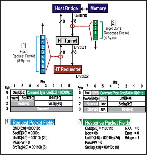

Example 6:Flush Request

Problem: Device 2 (UnitID2) in Figure 7-8 on page 174, issues a Flush request which causes all previous posted writes in the same transaction stream (sourced by UnitID2) to be forced to host memory.

Figure 7-8. A Flush Request Issued By UnitID 2

graphics/07fig08.jpg

Example 6:Flush Request Packet Setup

(Refer to [1] in Figure 7-8 on page 174)

Command[5:0] Field (Byte 0, Bit 5:0)

This is the Flush request command code. There are no option bits. For this example, field = 000010b.

SeqID[3:0] Field (Byte 0, Bit 7:6) and (Byte 1, Bit 6:5)

This field is used to tag groups of requests that were issued as part of an ordered sequence. Flush requests are never part of an ordered sequence, so this bit should be cleared. Setting SeqID[3:0] to a non-zero value may have indeterminate results. For this example, field = 0000b.

UnitID[4:0] Field (Byte 1, Bits 4:0)

For both upstream and downstream requests, this field is programmed with the UnitID of the requester. UnitID is assigned during initialization by configuration software. In this example, the request originates at Device 2 (UnitID2). For this example, field = 00010b.

PassPW Bit Field (Byte 1, Bit 7)

This bit is cleared in a Flush request so that the request will perform its intended function: pushing earlier posted writes ahead of it. Setting this bit = 1 may have indeterminate results. For this example, field = 0b.

Example 6:Flush Request, Sequence Of Events

(Refer to Figure 7-8 on page 174)

  1. After UnitID2 checks its transmitter non-Posted Request (CMD ) flow control counter for credits, the transmitter interface asserts CTL and starts sending out the Flush request packet information. On this eight bit interface, the transmitter sends one byte of request packet info during each successive bit time, least significant byte first.

  2. When the tunnel receives this Flush request, it will check its own transmitter non-posted request (CMD) flow control counter for the upstream link and prepare to reissue the request towards the host bridge.

  3. When the host bridge receives the Flush request, it will check the UnitID in the Flush request against the UnitID of each posted write request it has pending. Any matches indicate a posted write request which must be completed (they are in the same transaction stream).

  4. Once the Flush is done, the Host Bridge prepares initiate a Target Done response to the requester.

Example 6: Flush Response Packet Setup

(Refer to [2] in Figure 7-8 on page 174)

When the Host Bridge has completed the Flush to memory (or downstream for peer-to-peer traffic) it prepares to return a Target Done response to the original requester (UnitID2). The purpose of the response is to inform the requester the operation is done and that it may take any action that may have been pending its completion.

Command[5:0] Field (Byte 0, Bit 5:0)

This is the command code for the Target Done Response. There are no option bits in this field. For this example, field = 110011b.

UnitID[4:0] Field (Byte 1, Bits 4:0)

Because this response is being issued by a Host Bridge and traveling downstream, the UnitID field carries the identity of the original requester (UnitID2). For this example, field = 00010b.

Bridge Bit Field (Byte 1, Bit 6)

Set by host bridges in responses they issue downstream (as in this example) so devices may distinguish upstream and downstream responses. For this example, field = 1b.

PassPW Bit Field (Byte 1, Bit 7)

This bit indicates whether this packet may pass packets in the posted request channel (for same transaction stream). This bit should be clear in Flush request and the subsequent Target Done response. For this example, field = 0b.

SrcTag[4:0] Field (Byte 2, Bits 4:0)

The field is set to the same value as seen in the Flush request. In our example, the Source Tag was 6. For this example, field = 00110b.

Error Bit Field (Byte 2, Bit 5)

In a read transaction, this bit in the response is set to indicate an error was encountered in obtaining requested data. In this example, there were no errors. See Chapter 10, entitled "Error Detection And Handling," on page 229 for a discussion of how response errors are handled in HyperTransport. For this example, field = 0b.

NXA Bit Field (Byte 3, Bit 5)

This response bit is only valid if the Error bit (Byte 2, Bit 5) is set. IF NXA and Error are both set, the original Flush request did not find the proper target at all, and the Target Done response is being returned by a device at the end of the chain. For this example, field = 0b.

Example 6: Flush Response, Sequence Of Events

(Refer to Figure 7-8 on page 174)

  1. When the Host Bridge completes the forwarding of all posted write data for the transaction stream being Flushed, it prepares a Target Done response packet which will be routed back to the requester as a confirmation that the Flush is complete. There is no data returned with a Target Done response. The Host bridge programs the UnitID[4:0] and SrcTag[4:0] fields with the same information that was contained in the Flush request. It also sets the Bridge bit indicating a downstream response, and clears the error bits.

  2. Assuming it has credits in its Response flow control buffer counter, the Host Bridge transmitter then sends one byte of the four byte Target Done response packet during each successive bit time on its 8-bit interface. The CTL signal is asserted during the transmission of the response, and the least significant byte is sent first.

  3. When the tunnel receives the Target Done response from the Host Bridge, it checks the Bridge bit to see if it is set (it is) and the UnitID to determine if the response belongs to it (it doesn't). Unable to claim the response, the tunnel forwards the packet as-is downstream to the next device.

  4. When the response reaches Device 2 (UnitID 2) it is decoded and claimed. The SrcTag[4:0] field identifies the particular outstanding request this response is associated with (in this case, transaction #6).

A Few Notes About Flush Operations

  • Flush requests are intended to make previous write data "globally visible" in the host. To do this, any posted write data still in buffers between the sender and memory must be forwarded. The Target Done response at the end of a Flush is confirmation that the operation is complete.

  • There is no Isoc bit associated with a Flush because these requests do not affect traffic in the isochronous virtual channels.

  • If one or more of the posted writes which preceded the Flush operation targeted another device (called a peer-to-peer transaction) instead of main memory, then when the Target Done response returns confirming the completion of the Flush operation, it only guarantees that those posted writes were chased to the Host Bridge; they may not have reached the target yet.

  • Flush requests are only sent from devices to host bridges, or from one host bridge to another. Tunnels are not required to take any special action with a Flush other than to forward it in the direction it is already moving.

  • If a Flush request mistakenly reaches an end-of-chain device, it is required to decode the command and return the required Target Done response with the Error and NXA bits set.


HyperTransport System Architecture
HyperTransportв„ў System Architecture
ISBN: 0321168453
EAN: 2147483647
Year: 2003
Pages: 182

flylib.com © 2008-2017.
If you may any questions please contact us: flylib@qtcs.net