Example 4: Dword Read Request
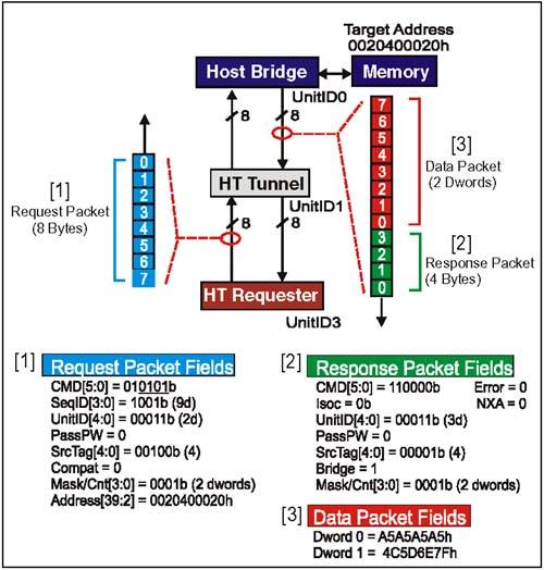
Example 4:Dword Read RequestProblem: Device 3 (UnitID3) in Figure 7-6 on page 161 targets main memory with a sized (dword) read of two dwords. Start address is 0020400020h; this request is part of an ordered sequence (#9). Figure 7-6. DMA Dword Read Targeting Main Memory Example 4: RdSized (Dword) Request Packet Setup(Refer to [1] in Figure 7-6 on page 161) Command[5:0] Field (Byte 0, Bit 5:0)This is the sized read (RdSized) command code. There are several option bits within this field (see underlined bits below). Assume dword (bit 2) and coherency (bit 0) bits are enabled; the Isoc (bit 1) and response may pass posted requests (bit 3) bits are disabled. This encoding describes a RdSized (dword) request which must assure coherency with CPU caches. For this example, field = 01 0101 b. SeqID[3:0] Field (Byte 0, Bit 7:6) and (Byte 1, Bit 6:5)This field tags groups of requests that were issued as part of an ordered sequence. In this example, this request is part of ordered sequence #9 for this transaction stream. Tunnel devices are required to maintain the ordering of each request from a single transaction stream that carries the same non-zero sequence ID. For this example, field = 1001b. UnitID[4:0] Field (Byte 1, Bits 4:0)This field is programmed with the UnitID of the requester. In this example, the request originates at Device 3 (UnitID3). For this example, field = 00011b. PassPW Bit Field (Byte 1, Bit 7)This bit is carried with read requests and isn't used until the response is generated. At that time the PassPW bit in the response will be set to match this bit. For this example, field = 0b. SrcTag[4:0] Field (Byte 2, Bits 4:0)This field tags the 32 outstanding non-posted transactions allowed to each UnitID. The code is assigned by the requester from a pool of available tags. Assume that the tag for this read request is 4. For this example, field = 00100b. Compat Bit Field (Byte 2, Bit 5)Used by bridges to tag downstream requests targeting the compatibility chain (where subtractive decoder is found). Reserved field for upstream requests. For this example, field = 0b. Mask/Count[3:0] Field (Byte 2, Bits 7:6) and (Byte 3, Bits 1:0)For a dword read request, the value programed into this field should be dword count-1. In this example, the transfer is two dwords. For this example, field = 0001b. Start Address Field (Bytes 4-7, Bit 7:0) and (Byte 3, Bit 7:2)This field is used to set up the 40-bit target start address. For this example, the target address in the main memory portion of the system memory map. For this example, the 40-bit address = 0020400020h. Example 4: RdSized (Dword) Request, Sequence Of Events(Refer to Figure 7-6 on page 161)
Example 4:Dword Read Response Packet Setup(Refer to [2] in Figure 7-6 on page 161) When the Host Bridge has completed the read of memory on behalf of the requester, it prepares to initiate a read response to the original requester (UnitID3). The purpose of the response is to inform devices in the topology that read data follows , and identifies who the recipient should be. Many of the fields in the Host Bridge read response reflect the setting of similiar fields in the request which caused it. Command[5:0] Field (Byte 0, Bit 5:0)This is the command code for the Read Response. There are no option bits in this field. For this example, field = 110000b. Isoc Bit Field (Byte 0, Bit 7)This bit indicates whether this response should travel in the isochronous response virtual channel as it moves back to the original requester. Because the request which caused this response was not isochronous, this bit will not be set. For this example, field = 0b. UnitID[4:0] Field (Byte 1, Bits 4:0)For responses moving downstream, (as this one is), the UnitID field contains the Unit ID of the original Requester and is used much like an address to help route the response to the proper device. For this example, field = 00011b. Bridge Bit Field (Byte 1, Bit 6)Set by host bridges in responses they issue downstream (such as this example). Only downstream responses (Bridge = 1) may be claimed by non-bridges. For this example, field = 1b. PassPW Bit Field (Byte 1, Bit 7)This bit indicates whether this packet may pass packets in the posted request channel (for same transaction stream). Because the PassPW bit was not set in the original request, it won't be set here either. For this example, field = 0b. SrcTag[4:0] Field (Byte 2, Bits 4:0)The field is set to the same value as seen in the request. In our example, the Source Tag was 4. For this example, field = 00100b. Error Bit Field (Byte 2, Bit 5)In a read transaction, this bit in the response will be set to indicate an error was encountered in obtaining requested data. When the response finds its way back to the original requester, this bit means that the accompanying data is not valid. For this example, field = 0b. Count[3:0] Field (Byte 2, Bits 7:6) and (Byte 3, Bits 1:0)For dword reads, the response count field is programmed to match the Mask/Count[3:0] field in the original request. For this example, field = 0001b. NXA Bit Field (Byte 3, Bit 5)This response bit indicates a non-existent address error and is only valid if the Error bit (Byte 2, Bit 5) is set. For this example, field = 0b. Example 4: Sized (Dword) Read Data Packet(Refer to [3] in Figure 7-6 on page 161) The sized (dword) read request which caused this data packet to be sent specified a start address of 0020400020h and a transfer count of two dwords. For this example, the two dwords being read from memory are:
Example 4: RdSized (Dword) Response, Sequence Of Events(Refer to Figure 7-6 on page 161)
|
EAN: 2147483647
Pages: 182