5.7 High Availability Fibre Channel Disk Array
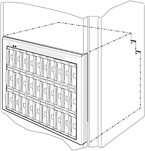
Figure 5-14. A3661A HA FC Disk Array This Fibre Channel peripheral has substantial storage capacity. It will hold up to 30 disk modules. Hewlett-Packard's highest capacity point is 18 gigabytes per disk module. This will increase with future releases. This disk array was designed specifically for use in Fibre Channel topologies. It is High Availability (HA) because it employs redundant components such as:
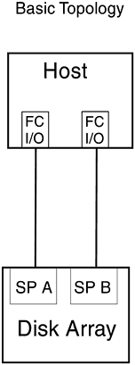
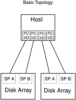
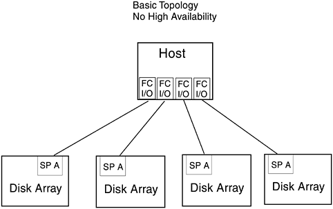
It is supported by the K-, D-, T- (600 only), and V-Class Hewlett-Packard Enterprise Servers running HP-UX 10.20 TFC or later. It has 1.063 gigabit per second optical Fibre Channel link speed and Fibre Channel Arbitrated Loop (FC-AL) topology is also supported. 5.7.1 Basic TopologyThe disk array protects against single points of failure with RAID (Redundant Array of Independent Disks) technology, global hot spares , and redundant, hot-swappable, customer- replaceable disk array components. Many of the components can be removed and replaced by the customer while the disk array is powered up, without removing it from the cabinet and without losing data. The RAID levels supported are 5, 3, 1/0, and 1. RAID level 0 and individual disk units are not supported because they provide no data redundancy. Disk arrays and hosts can be directly or indirectly connected to Hewlett-Packard FC-AL Hubs in a number of hardware topologies. Figure 5-15 shows the high availability version of the basic topology implemented on a host system with two host FC I/O adapters connected to a dual-SP disk array. Figure 5-15. Basic Topology, High Availability Version: Host with Two FC I/O Adapters One high availability version of the basic topology can be implemented in Figure 5-16 shows the high availability version of the basic topology implemented on a host with four host FC I/O adapters. Two of the FC adapters are connected to one dual-SP disk array while the other two FC adapters are connected to a second dual-SP disk array. Each connection of host adapter and SP creates a separate FC-AL. Additional disk arrays and FC adapters can be installed in T-Class servers. Figure 5-16. Basic Topology, High Availability Version: Host with Four FC I/O Adapters The nonhigh availability version connects a host or server to one or more single-SP disk arrays. This version provides no hardware redundancy and does not protect against single points of SP, FC cable, host FC I/O adapter, or internal SCSI-2 bus failure. If any of these components fail, the disk array becomes unavailable and applications cannot continue to run. The disk array remains unavailable until the failed hardware component is replaced. Applications can continue to run after the failure of single disk modules within logical disk units (LUNs). Figure 5-17 shows the nonhigh availability version of the basic topology implemented on either a K-Class or T-Class with four FC I/O adapters connected to single SPs in four disk Each connection between adapter and SP creates a separate FC-AL. Additional disk arrays and FC adapters can be installed in T-Class servers. Figure 5-17. Basic Topology, NonHigh Availability Version: Host with Four FC I/O Adapters All the topologies covered up to this point are considered to be basic topologies and are limited in distance to 500 meters because they do not incorporate the use of a hub. Using a hub in the topology can increase the distance the Fibre Channel peripheral can be placed from the host, but remember it will also increase the complexity of the topology. The following figures will demonstrate the use of hubs in topologies when just connecting to disk arrays.The use of hubs not only increases distance but also the degree of high availability and storage capacity available to the host(s). Each instance of the single-system distance topology generally uses the following hardware components:
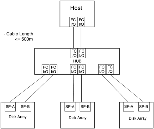
One or two single-distance topologies can be implemented in D-Class and K-Class systems, and up to 11 instances of this topology can be implemented in T-Class servers. 5.7.2 Distance TopologyFigure 5-11 illustrates the single-system distance topology with one host with two FC I/O adapters and three dual-SP disk arrays. In this example two of the HP FC-AL Hub's ten ports are unused. This topology uses one 10-port HP FC-AL Hub. The two FC I/O adapters in the single host attach to two ports in the HP FC-AL Hub, providing redundant hardware paths between the host and the HP FC-AL Hub. The SPs of dual or single-SP disk arrays attach to some or all of the remaining eight HP FC-AL Hub ports. This topology creates a single FC-AL that resembles a star topology with the HP FC-AL Hub acting as the central switching element. The 10-port HP FC-AL Hub is inserted between the host and the disk arrays, increasing both the number of arrays (and total disk capacity) that can be connected to a single host and the total length of the FC cabling. The HP FC-AL Hub is a single point of failure in this topology. Figure 5-18. Single-System Distance Topology Supported cable lengths for each segment of the FC-AL include 2 m, 16 m, 50 m, 100 m, and 500 m. The maximum combined cable lengths for all segments, that is, the total length of the FC-AL, should not exceed 5000 m because performance can degrade due to propagation delay. Because of this it is recommended that the total cable length of the FC-AL be as short as possible. Fibre optic cables in lengths of 2 m, 16 m, 50 m, and 100 m cables can be ordered from Hewlett-Packard. Fibre optic cables longer than 100 m must be custom-fabricated for each implementation. Like the basic topology, both high availability versions (two SPs per disk array) and nonhigh availability versions (one SP per disk array) of this topology can be implemented. For high availability implementations, up to four disk arrays with two SPs per disk array can be connected to the HP FC-AL Hub. For nonhigh availability implementations , up to eight disk arrays with one SP per disk array can be connected to the HP FC-AL Hub. For high availability, up to four dual-SP disk arrays can be attached to an HP FC-AL Hub. The two FC I/O adapters installed in the host connect to the two remaining HP FC-AL Hub ports. If one SP fails, ownership of its LUNs can transfer automatically to the remaining operational SP through the other FC adapter. If a primary and an alternate path have been configured in LVM, LVM can switch automatically and transparently to the alternate path. Likewise, if one host adapter fails, or if one FC cable from the host to the HP FC-AL Hub or from the HP FC-AL Hub to one of the dual-SP disk array fails, that disk array can still be accessed via the alternate hardware path. The HP FC-AL Hub is a single point of failure in this topology. If the HP FC-AL Hub fails, no communication between the host and any of the disk arrays is possible. For nonhigh availability, up to eight single-SP disk arrays can be attached to the HP FC-AL Hub. If the single SP or the FC cable between the HP FC-AL Hub and an array fails, no I/O operations are possible between the host and the disk array with the failed SP. If one FC adapter fails in the host, the disk array can still be accessed via the hardware path through the other operational FC adapter. If the HP FC-AL Hub fails, no communication between the host and any disk arrays is possible. 5.7.3 High Availability TopologyThe high availability topology increases the availability of the single system distance topology by protecting against single points of HP FC-AL Hub failure with the use of redundant HP FC-AL Hubs. Adding a second HP FC-AL Hub also increases the number of hosts and disk arrays that can be connected to a single FC-AL. Each instance of the high availability topology uses the following hardware components:
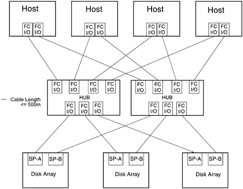
As its name implies, the high availability topology supports only dual-SP disk arrays. Because the objective of this topology is to use redundant hardware components to provide high availability, disk arrays with single SPs are not supported. All hardware components and paths are redundant. If any hardware failure occurs, I/O communication between host and disk array can be completed through another path. Figure 5-19. High Availability (redundant loop) Topology In this topology each host uses two FC I/O adapters and each disk array uses dual SPs. One adapter in each host and one SP in each disk array connect to one HP FC-AL Hub, forming one FC-AL. The second adapter in each host and the second SP in each disk array connect to the second HP FC-AL Hub, cabled into a separate FC-AL. This creates two redundant FC-ALs. Because each HP FC-AL Hub has ten ports, either two hosts and eight disk arrays or four hosts and six disk arrays can attach to each HP FC-AL Hub. If any hardware component (SP, host FC I/O adapter, HP FC-AL Hub, or fibre optic cable) fails in one FC-AL, the I/O communication between hosts and disk arrays can continue through the other FC-AL. Supported cable lengths for each segment of the FC-AL include 2 m, 16 m, 50 m, 100 m, and 500 m. The maximum combined cable lengths for all segments, that is, the total length of the FC-AL, should not exceed 5000 m because performance can degrade due to propagation delay. Because of this it is recommended that the total cable length of the FC-AL be as short as possible. Fibre optic cables in lengths of 2 m, 16 m, 50 m, and 100 m cables can be ordered from Hewlett-Packard. Fibre optic cables longer than 100 m must be custom-fabricated for each implementation. 5.7.4 High Availability, Distance, and Capacity TopologyThe high availability, distance, and capacity topology expands on the high availability topology by using cascaded HP FC-AL Hubs to increase the distance of each FC-AL and the number of devices that can be interconnected on the FC-AL. Cascaded HP FC-AL Hubs are two HP FC-AL Hubs connected together. Each instance of this topology uses the following hardware components:
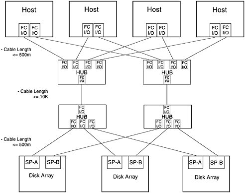
Like the high availability topology, this topology supports high availability by using redundant FC-ALs. If a hardware component (FC adapter, HP FC-AL Hub, SP or cables) in one FC-AL fails, I/O communication between hosts and disk arrays can continue through the other FC-AL. The increased distance is supported by using 10 k fibre optic cable to connect each pair of cascaded HP FC-AL Hubs. If distance is a requirement, it is managed between the two HP FC-AL Hubs. The distance from hosts to HP FC-AL Hubs and from disk arrays to HP FC-AL Hubs should be minimized. Supported cable lengths for each segment of the FC-AL include 2 m, 16 m, 50 m, 100 m, 500 m, and 10 k. The maximum combined cable lengths for all segments, that is, the total length of the FC-AL, should not exceed 11 k because performance can degrade due to propagation delay. Because of this it is recommended the total cable length of the FC-AL be as short as possible. Fibre optic cables in lengths of 2 m, 16 m, 50 m, and 100 m cables can be ordered from Hewlett-Packard. Fibre optic cables longer than 100 m must be custom-fabricated for each implementation. In this configuration a maximum of nine SPs can be attached to an HP FC-AL Hub's tenth port is used to connect to the other HP FC-AL Hub in the cascaded pair, rather than to a host adapter as in the high availability topology. Figure 5-20. High Availability, Distance, and Capacity Topology 5.7.5 Campus TopologyThe campus topology uses the same hardware components as the high availability, distance, and capacity topology. The components for each instance of this topology include:
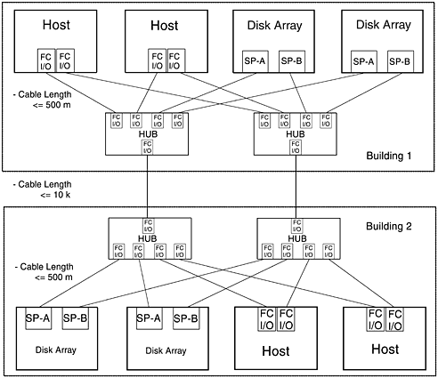
This topology is almost identical to the high availability, distance, and capacity topology. The difference is that in the campus topology one-half of the host systems, HP FC-AL Hubs, and disk arrays are located in one building while the other half of the hosts, HP FC-AL Hubs, and disk arrays are located at another site. The distribution of systems and hardware between two physical sites provides protection against a power failure or some other catastrophic site-wide failure. Figure 5-21. Campus Topology |
EAN: 2147483647
Pages: 53
- Key #1: Delight Your Customers with Speed and Quality
- Beyond the Basics: The Five Laws of Lean Six Sigma
- When Companies Start Using Lean Six Sigma
- Making Improvements That Last: An Illustrated Guide to DMAIC and the Lean Six Sigma Toolkit
- The Experience of Making Improvements: What Its Like to Work on Lean Six Sigma Projects
