5.6 Fibre Channel Arbitrated Loop Hub
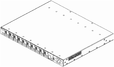
Figure 5-8. A3724A/A4839A FC-AL Hub The FC-AL hub is available in shortwave and long-wave models. Both models are available in stand-alone or factory-racked configurations. The AZ models are the factory-racked models. 5.6.1 Features
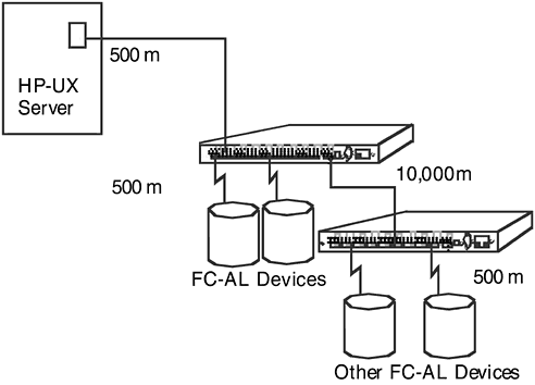
5.6.2 Shortwave Hub (HP A3724A/AZ)The short-wave hub supports 10 non-OFC (non- open fiber control) shortwave FC-AL connections. In arbitrated loop topology, the data rates and wavelength between ports must be the same. The shortwave hub supports only gigabit shortwave to gigabit shortwave connections using fiber cables. For the shortwave hub, Hewlett-Packard recommends 50 micron multimode fiber cable for new installations but supports 62.5 micron multimode fiber cable with SC-style connectors in existing installations. Installations can mix 50 micron and 62.5 micron cables. Using a 50 micron multimode cable, the short-wave hub supports distances up to 500 meters between a server host and the hub, between a hub port and a connected FC-AL device, and between two hubs. The maximum distance between a host server and FC-AL devices connected to cascaded shortwave hubs is 1500 meters . 5.6.3 Long-wave Hub (HP A4839A/AZ)The long-wave hub supports nine non-OFC, shortwave devices and a second long-wave FC-AL hub. The long-wave hub supports shortwave gigabit to shortwave gigabit connections from ports 1 through 9 using fiber cables. The long-wave hub also supports a long-wave hub to long-wave hub connection from the long-wave port. For the long-wave port, Hewlett-Packard recommends 9 micron multimode fiber cable. For ports 1 through 9, Hewlett-Packard recommends 50 micron multimode fiber cable for new installations but supports 62.5 micron multimode fiber cable with SC-style connectors in existing installations. For ports 1 through 9, the long-wave hub supports distances of 500 meters between the port and a connected FC-AL device. For the long-wave port, the long-wave hub supports distances up to 10 kilometers between two long-wave hubs. Figure 5-9. Cascaded Long-wave Hub Topology 5.6.4 Plan the FC-AL ConnectionsThe hub does not require drivers or specific versions of the HP-UX operating system, but FC-AL devices that connect to the hub do. Contact an HP sales representative for information on hardware and software requirements for the FC-AL devices you plan to connect to the hub.
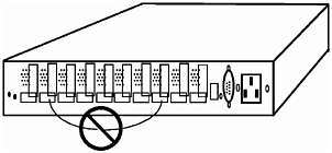
5.6.4.1 Correct Cabling ExamplesIn a cascaded configuration, connect any port on the first hub to any port on the second hub. The following example includes all 18 nodes in the loop formed by FC-AL Device 1, Hub A, Hub B, and FC-AL Device 2. FC-AL Device 1 is connected to Port 1 on Hub A; Port 10 of Hub A connects to Port 1 of Hub B, and Port 10 on Hub B connects to FC-AL Device 2. In this configuration, Port 10 on Hub B can connect to any FC-AL device. This is just one example of cascaded hubs. The connection between hubs can occupy any combination of ports. Figure 5-10. Cascaded Shortwave FC-AL Hub Configuration 5.6.4.2 Incorrect Cabling ExamplesThe following illustrations are examples of incorrect cabling. For example: Do NOT cable together two ports on the same hub. Ports between the two connections will be eliminated from the loop. Figure 5-11. Incorrect Cabling Example: Connected Ports on the Same Hub Do NOT attach more than one cable between any two hubs. Figure 5-12. Incorrect cabling example: more than one cable connection between hubs Do NOT attempt to connect a hub to more than one other hub. Figure 5-13. Incorrect cabling example: more than two hubs connected |
EAN: 2147483647
Pages: 53


