2.2 Transmission Technologies
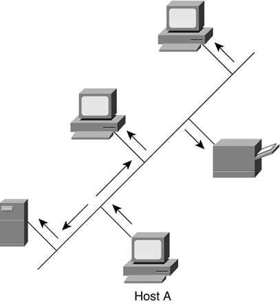
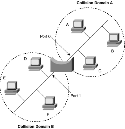
| The last section gave an overview of where a Juniper Networks router fits into the scheme of a network; this section will discuss those LAN and WAN technologies at Layer 2 that connect the routers to each other. As you learn to configure a Juniper Networks router in Part III, you will see it is best to configure the network by the layers up the OSI model (starting at Layer 1 and moving upward through the layers ). Starting at Layer 1, the physical layer, if the cable or fiber is not plugged in or is plugged in incorrectly at the physical layer, nothing else will work no matter how well it is configured. If Layer 2 is not working properly, then Layer 3 will not communicate. This is why even though routers work primarily at Layer 3 to forward packets, it is important to know what is happening at the data link layer as this is the layer that the network packets will flow across. After the physical layer is connected, the data link layer is configured next . After the data link layer, the network layer addressing is assigned. That is where the power of a Juniper Networks router resides, in its ability to forward IP packets. Data link protocols can be grouped into two categories: LAN and WAN protocols. Originally, the difference between LAN and WAN technologies had to do with the distance the protocols could cover geographically . With advances in technology, that distinction is no longer as clear. Ethernet is an example of a broadcast protocol (LAN), while Frame Relay, ATM, PPP, and High-Level Data Link Control (HDLC) are examples of nonbroadcast protocols (WANs). 2.2.1 LAN ProtocolsOriginally, data devices were connected directly to each other. This created a mess quickly because as more devices wished to speak to each other, each would have to add connections for all others. Ethernet is a standard LAN protocol that allows more than two users to be connected to the network at the same time. As seen in Figure 2-7, five devices are connected to the same Ethernet link. This allows all the devices to hear whenever any device talks. Think of a hallway with five people standing in doorways. If one wishes to talk to another three doors down, everyone else will hear him or her at the same time. This is called a broadcast-type network protocol. When host A sends out data, every device on the link will receive and look at it to determine if it is the intended receiver. If not, it will discard the data. Figure 2-7. Example of Using Ethernet to Connect Devices In Ethernet, the group of devices that can hear each other's transmissions is called a collision domain because sometimes two devices try to talk at the same time and their transmissions collide. They will then send their transmissions again at slightly different, randomly determined times. There has to be a random function in the resending, or the devices would send again at the same time and have another collision. As more devices fill a collision domain, more collisions occur. A bridge can be inserted to break the collision domain in half, effectively allowing everyone more talking time. When one device does not know the data link address for a destination, or if a device wants to send data to everyone at once, it sends what is called a broadcast, a frame that has an address that everyone will listen to. Bridges forward broadcast frames because they do not know for whom the frame is intended. A bridge learns the Layer 2 addresses of the connected devices on the different ports of the bridge, then records the data link source addresses of the devices connected to each port by listening to the communications. It can then determine when it has received a frame from one port that is destined for a device located on another port (if a bridge does not know which port a device is on, it will send the frame out to all but the incoming port). As a bridge learns the addresses of the devices connected to each port, it will keep these in a temporary table. A bridge can remove an address from the table if it hasn't heard from a device for a specified time. If the frame is destined for a device that is not in the bridge's table, it will forward the frame out of every port except the originating port. For example, in Figure 2-8 a bridge connects two collision domains. The bridge keeps a table that maps the Layer 2 addresses of devices to the ports they reside on. If collision domain A sends a frame to collision domain B, then port 0 will hear the transmission and look up the destination port for B. If the bridge knows that B is also off port 0, then it will drop any traffic from A, since B will get it directly. If the bridge does not know on which port B resides, then it will forward that traffic to any port except the one from which the transmission was received to ensure that no matter where B is, it will receive the transmission (in this case the bridge would forward that data to collision domain B). Figure 2-8. A Bridge Forwarding Traffic Between Collision Domains On a network, one device may wish to communicate with all other connected devices at once and thus sends a broadcast. All devices that can receive a Layer 2 broadcast form a group called the broadcast domain. Although bridges may have cut down collisions, by forwarding broadcasts bridges can still create congestion. This can be a problem in LANs if too many devices are broadcasting. Routers are then used to break up the broadcast domain. As mentioned earlier, Ethernet is a type of broadcast protocol. For a wonderful in-depth discussion of bridging concepts, read Radia Perlman's Interconnections, Second Edition , (Addison-Wesley, 2000). 2.2.1.1 The Standard: EthernetEthernet is a standard data link layer protocol that is used for LAN connections. Ethernet is the basis for the 802.3 IEEE specifications that govern how the protocol is to be implemented. This ensures that different manufacturers will make equipment components that will communicate with each other. A router, a switch, and a server with Ethernet interfaces should all communicate properly if the interfaces adhere to the standards. Ethernet is a carrier-sense multiple-access with collision detection (CSMA-CD) protocol. In the physical layer, bits are sent with low voltages of electricity called a carrier. An Ethernet device will listen for a carrier before sending to ensure no one else is using the network. In this way, many stations can access the network. If a collision is detected , the devices whose traffic collided send a blocking signal to ensure that everyone realizes that a collision occurred and waits a certain amount of time, plus a small random amount, before retransmitting. The random amount of time added to the specified time keeps two devices that have collided from recolliding. Regular Ethernet typically runs at 10Mbps, or 10 million bits every second, and is usually transmitted over unshielded twisted pair (UTP), such as Category 5 cabling. In a nonbridged environment, every device in a collision domain on the Ethernet has to share the 10Mbps. In a desktop switching network, every (or at least most) devices will have their own 10Mbps Ethernet connection directly connected to the switch, which reduces the collision domain, but since every device can still receive all other's broadcasts, all are still all in the same broadcast domain. A switch has a backplane (sometimes called a switch fabric ) through which data passes when it has been received in one port and must be forwarded out another. The Ethernet protocol uses addresses in the Layer 2 frame to send and receive data. This Layer 2 addressing is called the MAC address. This is a 48-bit address that uniquely identifies the device on the network. On Juniper Networks interfaces these are called hardware addresses and are written in a hexadecimal format, such as 00:90:69:9e:80:00 . These addresses are usually hard-coded at the factory into the Ethernet card and are often burned in to the network interface card (NIC), so they are sometimes also known as burned-in addresses (BIAs). Figure 2-9 shows an Ethernet frame separated into fields. The parts of an Ethernet frame are used to deliver the frame to the receiver, allow the receiver to know which device originated the frame, and to ensure that the frame arrived intact.
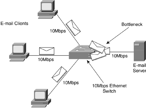
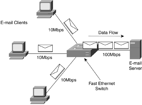
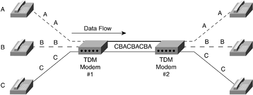
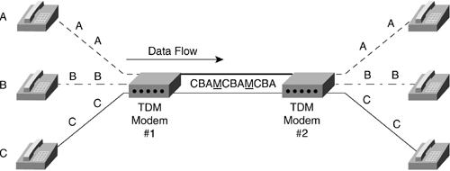
Figure 2-9. Fields in an Ethernet Frame Ethernet can run in half-duplex or full-duplex mode. Half-duplex is the mode of communications when only one party to the conversation can talk at a time. This is similar to communicating by walkie-talkie: The receiver must wait until the sender finishes before sending a reply. Full-duplex is the mode that allows both the devices to send and receive at the same time. This would be similar to talking on a telephone: Both devices can transmit and receive simultaneously . Note Most end-stations, like workstations or servers, are half-duplex by default, whereas most switches and routers will either attempt to autonegotiate or be set to full-duplex by default. It is usually best just to set what you wish to ensure both sides of the link are set alike. Since every device can hear a broadcast from any device in that broadcast domain, an easy way for a station to learn the Layer 2 MAC address for a destination Layer 3 IP address is to broadcast a request for the owner. If you are device A and you have data for a Layer 3 address B, but you don't know the Layer 2 MAC address for B, you simply send out a broadcast Ethernet frame to everyone asking who owns Layer 3 address B and what its Layer 2 MAC address is. Device B sends the proper MAC address, and now A can send data across the physical link with the appropriate Layer 2 destination address. This process of broadcasting to all stations in a broadcast domain for a particular Layer 2 address is called Address Resolution Protocol (ARP). It allows a sending device to find out what the Layer 2 address is for a Layer 3 destination. But what happens if the device determines that the Layer 3 address is not within the broadcast domain? To determine whether or not a Layer 3 address is in the broadcast domain, the source device sees if the destination address is within the range of the local broadcast domain. An administrator has configured a router to allow the forwarding of data out of the network. The router in this case is known as a default gateway or gateway of last resort. Once the device determines that the destination host is not in the broadcast domain, it will send an ARP request to the router. The router is where a device sends data that is destined for a nondirectly connected network to allow the router to pass the data to another network. 2.2.1.2 Fast EthernetSometimes the flow of data can cause bottlenecks at areas of congestion. Giving all the devices on a network a full 10Mbps sounds like a good idea at first, but this can overload connections that many devices try to access at once. Even if five users trying to send data to the same server all have 10Mbps connections, the server can only receive at a rate of 10Mbps no matter what. The connection to the server would be a bottleneck. Another common bottleneck can occur when many users on a switched 10Mbps Ethernet connection are trying to send or receive information through one router or other single exit point on a network. For example, everyone arrives at work in the morning and the first thing they wish to do is check their e-mail, as shown in Figure 2-10. Figure 2-10. A 10Mbps Bottlenecked Ethernet Network Fast Ethernet was created to eliminate some of the bottlenecks. This allows the Ethernet standard to be implemented at 100Mbps. With an Ethernet switch able to manage faster communications, devices could get a Fast Ethernet connection to the switch if that was an area of congestion. Several users at a normal 10Mbps could then transfer data simultaneously to a server connected to the switch at 100Mbps as shown in Figure 2-11. The server has a connection 10 times the speed of the connection that each of the clients has. This means that the server can talk with all three of the devices and still have 70Mbps left in the bandwidth available to the switch for more data to be sent. In addition, Fast Ethernet can be implemented over UTP copper (similar to standard Ethernet) or fiber-optic cabling. Fiber- optic cabling allows transmission over much longer distances. Figure 2-11. A Mixed 10- and 100Mbps Ethernet Network 2.2.1.3 Gigabit EthernetGigabit Ethernet is primarily run on fiber. With a speed of 1,000Mbps, this is a LAN protocol suited to use between network devices where high bandwidth is needed. As a 100Mbps connection can alleviate bottlenecks from the end-stations for many 10Mbps connections, so can Gigabit Ethernet alleviate bottlenecks caused by too many 100Mbps connections accessing the same end-stations. This covers the Ethernet protocol group and its various speeds. Next is the group of WAN protocols and their specifics. These are the protocols that are primarily used to join LANs or groups of LANs together over large geographic distances. 2.2.2 WAN ProtocolsWAN technologies were developed to cross very large geographical distances. Originally, this might have applied to long-distance telephony. An early example of a WAN would have been the connections that linked two small towns' switchboards. These towns' switchboards were local for themselves , but were required to make connections across distances to pass information. This section describes the modern protocols used to transfer data across great distances. 2.2.2.1 WAN TechnologiesThe telephone is one of the earliest methods of using a network to pass information. The circuits were set-up manually by an operator switching the connections together. One circuit was required for each conversation, and the wire could only hold that one conversation. Once the telephone companies digitized voice telephone circuits, multiple conversations could then be combined on a single wire. This process, called multiplexing, greatly increased the numbers of circuits that could be transmitted on the available wire that connected the large telephone switches. Instead of requiring a single set of wires for each circuit, now one set could run many circuits simultaneously. From this new development came a specific process for multiplexing digital circuits. It based the mixing of different circuits on timing. Each circuit had a place in the stream of 1s and 0s and could take its turn having data sent. As long as both ends agreed on the timing, the sending device and the receiving device would know which bits belonged to which circuits. This is known as time division multiplexing (TDM). In Figure 2-12, modem 1 is mixing the bits of circuits A, B, and C in a specific order using TDM. As long as modem B, on the right, is correspondingly configured, it knows which bits belong to which circuits and can separate and demodulate them appropriately back to separate circuits. Figure 2-12. TDM TDM devices originally had to be set up manually on both sides to correlate which circuits would be sent into which timeslots during the multiplexing. As this became more cumbersome with the addition of many more circuits, devices were invented that would have administrative digital information inserted into the normal circuit bits at regular intervals. This allowed the TDM devices to communicate with each other to automate many routine setup functions. This was known as in- band management because the management communications were taking place in the same data stream as the circuits were traveling. In Figure 2-13, TDM device A has inserted management bits (M) into the data stream to communicate with TDM device B. Figure 2-13. TDM with In-Band Management 2.2.2.2 DS HierarchyFurther developments of the TDM standard led to a full digital hierarchy in frastructure in America. Voice circuits are generated 8 bits at a time that are sampled 8,000 times per second, for a constant 64,000-bps circuit, or 64Kbps (1,000 bits = 1 kilobit). This digital hierarchy allows 64Kbps circuits to be multiplexed in greater numbers in a scalable manner. The 64Kbps circuit became the standard and was named a digital stream-0 (DS-0) to represent the base circuit. To allow the standard multiplexing of many DS-0s, a digital stream (DS) hierarchy was implemented in North America. When 24 DS-0s were multiplexed together, they created a DS-1. When DS-1s were no longer sufficient to handle the number of circuits required, 28 DS-1s were combined to create a DS-3. This ability to combine groups of circuits in great numbers allowed the TDM networks to grow at rapid rates. Globally, a DS hierarchy was implemented on the same DS-0, but on different multiplexed levels. The two most common DS hierarchies are the U.S. standard and the worldwide standard (sometimes called E standard) listed in Table 2-1. Table 2-1. DS Hierarchies
Due to the fact that the TDM networks were, at the lower level, the same 1s and 0s that data networks used, devices were created that allowed data networks to call one another just as people do using the phone: No modem was needed. A network administrator could install a DS-0, several DS-0s, or a DS-1, depending on the requirement. This allowed local networks to connect to each other over a wide area. Now, companies with LANs in different geographic regions could have fast digital connections between them. There is a disadvantage to circuit-switched networks, however. When a connection is brought up, even if not much data is being passed, the full bandwidth is taken for that particular connection. When a DS-0 connection is made, all 64Kbps is reserved for that connection, even if it isn't being used. There was a need for a type of connection that used only the bandwidth required or allowed traffic to multiple end points at once. This type of network needed to switch the actual packets instead of the entire circuit. 2.2.2.3 Frame RelayA technology was developed that allowed one port on a device to have connections to more than one destination device at the same time. The technology splits the physical port, or interface, into logical multiple interfaces that can have different Layer 3 addresses as if they were physically separate. The data for a particular destination that had been streamed in a specific timeslot would now be bundled in a packet. This allowed the packets themselves to be switched between destinations. Frame Relay is a nonbroadcast multiaccess (NBMA) technology. NBMA is considered nonbroadcast, for two reasons:
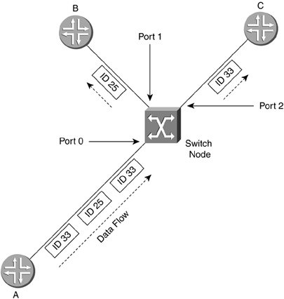
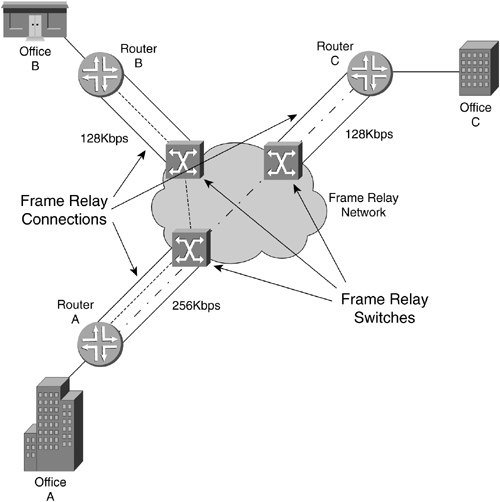
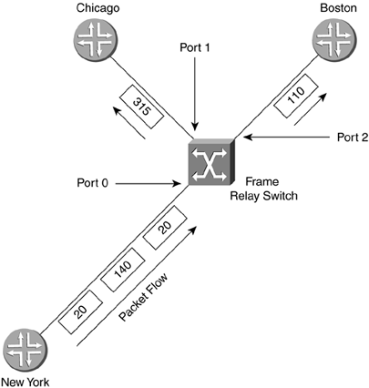
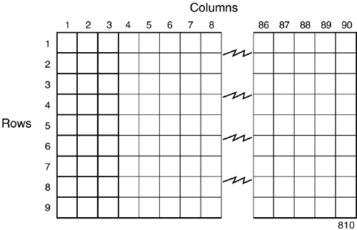
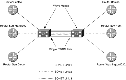
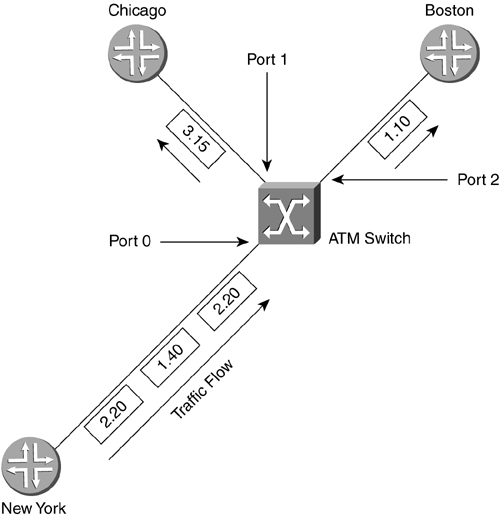
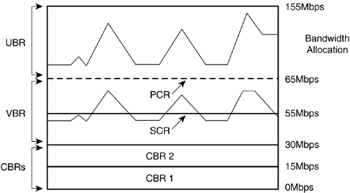
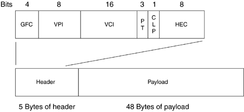
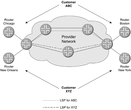
Unlike an integrated services digital network (ISDN) circuit, Frame Relay allows one physical connection to a WAN switch to have multiple Layer 3 addresses. NBMA technology allows the splitting up of the physical layer interface into logical or virtual data link layer units with different Layer 2 and Layer 3 addresses for each. The different Layer 2 addresses are needed so that the WAN switch knows in which direction to switch the frame. Not every station on an NBMA network can be sent to at once; only those in which there is a connection set up through the WAN switches can. In the header of the frame, there is an identifier to allow the switch to forward the frame in the appropriate direction. Figure 2-14 shows an example of an NBMA network. Router A puts a Layer 2 identification (ID) number of 25 on any frame to go to router B and of 33 for any frame to go to router C. The switch node has a table that merely says: Any incoming ID 25 on Port 0, send out Port 1, and any incoming ID 33, send out Port 2. In this manner, router A has access to multiple devices with one physical connection, but cannot broadcast to both at once. These connections to the other routers are called virtual because they are not real. The routers act as if they are connected to each other, but in fact are connected to the switch node. Figure 2-14. NBMA Network Frame Relay operates on the premise of circuit-like data links that are permanently connected to other locations. These circuits are permanent because they don't have to be brought up and torn down as an ISDN connection would, but they serve the same purpose of maintaining a constant connection between two devices. In addition, they do not take up the whole physical interface. The interface can be divided logically between different Layer 3 addresses for different destinations. In Figure 2-15, office A has a 256Kbps leased line. The administrator wants two permanent virtual circuits (PVCs): one 128Kbps data link connection to office B and one 128Kbps data link connection to office C. Now office A can communicate with offices B and C at the same time. If this were a single connection circuit-switch technology, the connection between offices A and B would have to be disconnected in order for office A to communicate with office C. Figure 2-15. Frame Relay PVCs There are two different types of Frame Relay interfaces: point-to-point and multipoint. Point-to-point allows only two devices to be connected to one PVC. Multipoint allows more than two devices to be connected on the same PVC. But how does a packet-switched network (PSN) switch know where to send an incoming frame? In the beginning of the frame, before the actual data, is the data link connection identifier (DLCI), a 10-bit number that represents the PVC and is used as a Layer 2 address. Figure 2-16 shows an example of two point-to-point PVCs from New York, one each going to Chicago and Boston. New York has PVCs set up on DLCIs 20 and 140. Router Chicago has a PVC to New York using DLCI 315 and Boston has a PVC with New York on DLCI 110. When the New York router has to send a packet to a Layer 3 “network destination through Chicago, it will send the frame out with a DLCI of 140. If it has to send a packet through Boston, it will send the frame out with a DLCI of 20. When the frame switch sees the DLCI from port 0, it references its switching table, which says that any frame received on port 0 with DLCI 20 should be forwarded out port 2. Any frame received on port 0 with DLCI 140 should be forwarded out port 1. This tells the PSN switch in which direction the frame should be sent. This is the important part of the Layer 3 to Layer 2 handoff . New York only has one interface connected to the frame switch. The interface is split into virtual interfaces because you can have separate Layer 2 and 3 addresses on them. For the New York router, DLCI 20 would be mapped to one Layer 3 address (the one that can communicate to Boston) and DLCI 140 would be mapped to another Layer 3 address (one that could send and receive with Chicago). Figure 2-16. Frame Switch Using DLCIs As more branch offices wished to be connected to New York, more PVCs could be added, and the DLCIs configured to send the frames along the PVCs to their appropriate destinations. This covers two popular WAN technologies of both the circuit-switched and packet-switched types. As their speeds grew to the limits of electrical signals, optical devices were needed to increase the speeds and allow larger aggregation of the network connections. An optical standard that could accommodate both would be helpful. This optical standard would need the capability to carry many multiplexed DS circuits on one port. SONET and Synchronous Digital Hierarchy (SDH) were created to do just that. 2.2.2.4 SONET/SDHIn the TDM-standards arena, the DS standards evolved in North America (and Japan), and the E standards evolved in Europe, then spread throughout the rest of the world. In the optical-transmission arena, there are also two main standards: SONET was developed in the United States while SDH was developed for international use. These are two very similar physical standards for transmitting digital bits by light over fiber-optic cable. When the copper-based TDM networks at the DS-3 speed were demanded more by end users, a faster multiplexing scheme had to be implemented, one that could scale to much greater speeds than electric pulses over copper. In addition, the new multiplexing scheme would have to go further and be more flexible in inserting and dropping DS circuits. At the time, to drop one DS-0 and add another to a DS-3 required that all of the DS-1s could be separated (even if there was only one that needed to have a circuit inserted). An add-drop multiplexer (ADM) was developed to allow a particular timeslot's data to be removed and another's inserted in its place without the entire infrastructure having to be split apart and remultiplexed. SONET was developed to carry multiplexed DS circuits. The SONET architecture is built around a synchronous transport signal (STS). The STS is the electrical framing component that is then transmitted into an optical signal called an optical carrier, or OC. Since SONET is based on the TDM voice-circuit standards, the frame has to be sent 8,000 times a second to maintain DS hierarchy compatibility. This was extremely important because SONET was first used primarily to multiplex ISDN circuits. Since the DS-0 is 8 bits sampled 8,000 times per second, SONET transmission had to match that for consistency. The STS-1 is built around the user data called a synchronous payload envelope (SPE). The STS is broken into nine columns of 90 bytes for a total of 810 bytes. The transmission of 810 bytes at 8,000 times per second gives the base STS-1 a speed of 51.84Mbps. Out of 90 bytes in the column, there are a total of 3 bytes per row of header information. Figure 2-17 shows the STS-1 and SPE format. Figure 2-17. STS-1 and SPE Format Bytes 1 to 3 are the header bytes. Each Row has 3 header bytes for a total of 27 for the entire STS-1. Bytes 4 to 90 comprise the payload of each row. Each row is then sent one right after the other. Byte 90 of row 1 is transmitted before byte 1 of row 2. The SPE is packaged in 4-90-byte sections of the 9 rows. The main reason to show the STS in this format is to illustrate the order in which the bytes are sent. STS-3 combines three STS frames into a single set of rows and columns. Instead of 90 bytes in a row, there are a total of 270 bytes in a row. The headers for STS #2 and STS #3 are added directly behind the headers of STS #1. SPEs 1, 2, and 3 are multiplexed at the byte level, so the bytes are sent in the order 123, 123, 123 for the 261 bytes in the payload part of the row. Having a single STS capable of only carrying a single DS-3 did not help increase the capacity of the lines between switches. A format of three STS frames multiplexed together (called STS-3 or OC-3) allowed for three DS-3s to be combined together. The total capacity of the OC-3 is 155.52Mbps (3 x 51.84). When more bandwidth was required, standards were then implemented to combine 12 STS, 48 STS, and 192 STS frames for data rates of 622.08Mbps, 2,488.32Mbps, and 9,953.28Mbps respectively. To increase the flexibility of the SPE, not just a single DS-3 can be placed into an SPE to be framed in an STS, but many DS-1s, E-1s, or DS-0s can also be multiplexed in an SPE. An SPE can be divided up into seven virtual tributaries (VTs). A VT can carry four DS-1s or three E-1s, but cannot carry both. Different VTs in an SPE can carry different types of circuits, but within a VT they all have to be of the same type. Four DS-1s in seven VTs totals the 28 DS-1s in a DS-3. Although circuit-switched networks developed the SONET protocol to multiplex many DS circuits, packet-switched networks implemented SONET so they could use the scalability of the STS-3 for carrying data. Instead of having three STS SPEs, each broken into seven VTs, the STS-3 is left whole. This is called concatenation or unchannelized. The whole STS-3 can be packed with ATM cells or IP packets, giving data rates greater than 155Mbps. Sometimes this type of implementation is designated as OC-3c, with the lowercased c designating the concatenated SONET frame. When the STS is filled with IP packets, it is known as POS. SDH is the standard developed and used outside the United States. This implementation is based on synchronous transport module (STM) units, which use a base of 155.20Mbps (STM-1). An STM-4 connection is 4 x 155.520Mbps, or 622.080Mbps. In terms of bandwidth references, STM-1 equals an OC-3 (155.520Mbps). More information about SONET and SONET standards can be found at www.techfest.com/networking/wan/sonet.htm. 2.2.2.5 Dense Wave Division MultiplexingReaching up to OC-192 (approximately 10Gbps), SONET speeds have jumped tremendously in the past several years , but a new technology using SONET technology has increased these speeds by up to 64 times. This new technology is called dense wave division multiplexing (DWDM). SONET is an optical technology that basically consists of shining a light or laser down a glass fiber cable. Advances in laser and fiber technology have allowed different wavelengths (colors) of light to be transmitted across a single fiber-optic cable. The way this technology works is a wavelength multiplexer (wave mux) is fed several SONET links. The wave mux will convert each of the SONET streams into a specific wavelength on the DWDM link. One the far end, the wavelengths are demultiplexed into single SONET links that are then sent to their destinations. In Figure 2-18, routers Seattle, San Francisco, and San Diego have SONET links to a wave mux. The wave max converts each SONET link to a different wavelength and transmits them to the other end to be demultiplexed. Each wavelength is then converted back to normal and sent on its way to routers Boston, New York, and Washington D.C. In this scenario, because router Seattle is only connected with router Boston, it cannot transmit to router New York or router Washington D.C. In addition, router San Francisco is connected only to router New York, and router San Diego to router Washington D.C. Figure 2-18. DWDM This is a tremendous advance in increasing the capacity available to high-bandwidth networks. Each of the wavelengths of light can be a single data stream. As of this writing, the bandwidth transmission record is 64 x OC-768 transmitted 2,500 miles. This equals 2.56 terabits per second, or 2,560Gbps! Although routers from Juniper Networks do not have DWDM interfaces, there have been interoperability studies with DWDM device manufacturers. DWDM can be a key component of a core network with long-haul (LH) high-bandwidth links. 2.2.2.6 HDLCHDLC originally developed from protocols used to transport IBM systems network architecture (SNA) traffic that was used by mainframe computers across WAN links. HDLC is a full-duplex data link layer protocol for point-to-point, or sometimes multipoint, serial networks and is one of the most widely used. Originally IBM mainframes would talk to dumb terminals and poll them for data. The dumb terminals could only speak when spoken to and would have to wait their turn. As terminals became smarter , they were able to initiate their own communications with the mainframe and with each other. These necessary actions preceded the current two types of HDLC standard: unbalanced and balanced. Unbalanced mode is a master-slave -relationship-type mode. There is a primary and secondary station when two devices are connected via HDLC in unbalanced mode. The secondary station has to wait for the primary station to poll it before it is allowed to send traffic. That traffic will then be acknowledged by the primary and passed on. This was originally used for mainframe-to-terminal communications. Balanced mode allows both devices to talk to each other at will and is the only network implementation Juniper Networks uses for HDLC. Juniper Networks implements the Cisco version of HDLC because of the wide use of that particular version. 2.2.2.7 PPPPPP is another Layer 2 protocol only used for point-to-point connections, which is why it is called the Point-to-Point Protocol. This protocol also had earlier roots. Originally, Serial Line Internet Protocol (SLIP) was used in the earlier days of dialing into a device with a modem. SLIP was not a very good protocol; it had no error detection, only supported limited Layer 3 protocol implementations, and required complex IP configuration before connecting. PPP was then created and implemented (RFC 1331 www.ietf.org) as people started to use modems and computers to connect into networks. If you wished to dial into different networks, you did not wish to have to change your network configuration every time. PPP allows for dynamic address assignments and Layer 3 protocol connection, increased Layer 3 protocol support, error detection, encrypted authentication, and many other features. Most of the advanced features of PPP are used for the massive dialup networking systems of ISPs or corporate networks. These advanced features can include automatic IP address, default gateway, and subnet mask assignments after negotiating the initial connection. PPP can be used on routers for the negotiation and error-detection features. One of the best features of PPP is that because the negotiation has to take place to bring up a connection, that is a perfect time to do authentication if you wish to password some of the connections on your routers. The main thing to know about PPP is that it is also a Layer 2 encapsulation alternative to HDLC and Frame Relay and that it is the default interface encapsulation for T1/T3, E1/E3, and SONET Juniper Networks routers. PPP, HDLC, and Frame Relay are Layer 2 encapsulation types for POS. SONET can also be used for TDM multiplexing, but how does one get the best of Frame Relay's dynamic bandwidth capabilities and a circuit-switched network's (CSN) ability to grant high-quality service together with the speed of SONET? A technology was developed based on cells. These switched cells were switched like a packet, but were much smaller to allow a switch to minimize the delay as it switched them through the switch fabric. Instead of having a connection take the full bandwidth available, even if not using it, as synchronous networks did, this technology would allow dynamic bandwidth allocations based on priority and was therefore named asynchronous. 2.2.2.8 ATMAs companies grew, they were faced with ever growing separate voice and data networks. Large DS hierarchy voice-line infrastructures were installed next to large PSN data networks. There surely had to be a way to combine the two, but there were problems with combining these completely different types of information. Voice connections are very sensitive to delay, but are not necessarily sensitive to accuracy. If several bits of a voice conversation were lost, chances are they wouldn't be noticed unless the problem grew too large. If, however, some of the bits were delayed, then accelerated, then delayed, the conversation would become garbled. Data transfers are sensitive to accuracy, but not necessarily to delay. A file being transferred could be rendered unusable if even only one packet were missing, but it wouldn't matter too much if the transfer were undergoing the same acceleration/deceleration as a voice call. However, data usually requires a much higher data transfer rate to move large files or it would not be considered productive. Unfortunately, these data transfers that require high data rates can clog points through a network, causing delay. How do you keep the data transfer traffic from hogging all of the connection bandwidth to allow the delay-sensitive traffic some room to traverse the network unhindered? This is where ATM comes in. ATM was developed as a combination of ISDN and Frame Relay. This allows ATM the features needed to carry both delay-sensitive traffic and high data-rate traffic at the same time on only one network. ATM is another NBMA technology. The two main virtual connections of ATM are PVCs and switched virtual circuits (SVCs). ATM PVCs are similar to the PVCs in Frame Relay. They are up all the time at a specific bandwidth. SVCs, though, are demand connections: They are only created when needed. They are connected when needed and disconnected when not. For detailed information on ATM standards, visit www.atmforum.com. ATM uses virtual interfaces logical unit in a manner similar to Frame Relay for PVCs. Instead of a single DLCI to identify for which data link PVC the frame was intended, ATM was made much more scalable by creating paths and channels. 2.2.2.9 Virtual Paths and ChannelsATM has a physical interface that is split into virtual paths. Each path can then be divided up into virtual channels. If a router has multiple PVCs on one interface to other routers, the rest of the ATM network has to differentiate which data belongs to which PVC so the ATM network devices can accurately forward the data. A PVC is identified by the numbers that make up the path and channel. This path -channel pair makes an identification that is unique on the ATM connection between the router and the switch or from router to router. These identifiers for paths and channels are known as virtual path identifiers (VPI) and virtual channel identifiers (VCI). In Figure 2-19, three ATM interfaces are shown with logical paths and channels. Each path and channel has an associated ID to differentiate data for one destination from another, similar to a Frame Relay DLCI. The large left ATM interface has four virtual channels assigned. Path 57 has virtual channel IDs of 39 and 40, which would be written out as 57.39 and 57.40, respectively. Also on the left interface is path 68, which has VCI 37 and 38, which would be written out as 68.37 and 68.38. Both of the smaller right interfaces have a path 68 configured. A VPI/VCI pair only has to be unique for that interface. Figure 2-19. ATM Paths and Channels The ATM switch has a switching table mapped for all the paths and channels for all the ports. The PVCs through an ATM switch are manually configured either directly by an administrator or through management software. This is the manner in which data is passed switch to switch from the entry point of an ATM network to the exit through a PVC. VPI 0 and VCI 32 and under are reserved for specific ATM functions ”do not use these VPI/VCI pairs. In Figure 2-20, the router in New York has two PVCs on the interface that connects to the ATM switch. The ATM switch does not have to know anything about the Layer 3 addressing (switches work at Layer 2). When data is to be sent by the New York router to Boston, it has to send the data out the proper PVC. This PVC is VPI 2 and VCI 20 (2.20). When data is to be sent to the Chicago router, it is sent on the PVC 1.40. The ATM switch has a switching table to forward packets appropriately. When a cell is received by the switch on the New York port (port 0), the table says in port 0 on 2.20, "send it out port 2 on VPI/VCI 1.10." If data comes in on port 0 on PVC 1.40, it says "send it out port 1 on 3.15." The number 3.15 represents a cell with path 3, channel 15 identified in the cell header. Figure 2-20. Routing Using ATM PVCs ATM traffic can be given different priorities for leaving an interface. If many devices try to send to destinations on the other side of an ATM connection, a bottleneck can occur. This can create a situation where some data gets through and some doesn't. ATM circuits can be assigned priorities that assure that intended higher priority data gets sent. When the higher priority connections aren't fully using their assigned bandwidth, lower priority connections can use it. ATM can emulate TDM circuits like DS-0s, T-1s, or E-3s. This allows TDM connections to be mapped across an ATM network. This is known as circuit emulation. Internet data, such as e-mail, FTP, and Web pages, can also be transferred across an ATM network. This type of data is known as best-effort. Internet-type data originally had no assurances of being received at the destination if problems of congestion were encountered along the way. A problem arises with the two different ways that TDM and best-effort handle data traffic. TDM is based on a constant bandwidth speed requirement. Best-effort data is usually bursty , which is to say that it has peaks (high usage) and valleys (low usage) of bandwidth usage. ATM has controls to allow both types of data to be transmitted on the same network and to apply extra bandwidth to the lower-priority data when the higher-priority data is not using it. Circuit emulation technology requires a PVC with a constant bit rate (CBR) profile. A profile is a service category that allows ATM traffic to be treated differently. The CBR is set based on a steady stream in bits per second on data and has the highest priority. Variable bit rate (VBR) profiles allow for a steady sustained cell rate (SCR), but also a higher bit rate that can be burst up to for a specific time period, known as the peak cell rate (PCR). Bursting is the situation when an inordinately large group of cells is sent at once. The VBR profile has second priority after CBR. Internet-type data uses a profile called unspecified bit rate (UBR) because of the varied bandwidth requirements. There is no specified bandwidth at all. UBR has the lowest priority and gets whatever is left over after the CBR and VBR profiles have made their claim to the port. In Figure 2-21, the port traffic profile structure is illustrated with the two CBR PVCs ensuring their needed steady rates, then one VBR PVC getting the middle bandwidth, and any UBR traffic getting whatever is left over. The CBR 1 and 2 are both configured for 15Mbps each; the VBR has a sustained rate of 25Mbps with a peak of 10Mbps above the SCR; the UBR gets the remainder. Figure 2-21. ATM Profiles with Constant, Variable, and Unspecified Bit Rates Remember how ATM sends its data across a network in cells. As Frame Relay used frames at Layer 2, ATM uses cells with the VPI/VCI addressing in the header. The cells are extremely small to allow for low delay (called latency ) with mixed traffic types when bandwidth is limited. 2.2.2.10 The CellThe ATM cell is the standard unit used for transmission across an ATM network and is a total of 53-bytes long: 5 bytes of the ATM cell are used for addressing and header information, and 48 bytes of the cell are used for the payload of data. All ATM cells are 53-bytes long, allowing for consistency of transmission throughout the network. Sometimes when a Layer 3 packet is segmented to fit into the ATM cells, it doesn't completely fill the last cell. This cell has to be completed with padding. Padding is filler that doesn't mean anything, but is used to ensure the cell is the proper size. ATM cells come in two different types: user-network interface (UNI) and network node interface (NNI). UNI is a specification for the communications between an end device (such as a router) and an ATM switch. NNI describes the communication specification between ATM switches themselves. Figure 2-22 shows the make up of an ATM UNI cell.
Figure 2-22. Components of an ATM Cell ATM is has been around for a while and is very developed. It is also very flexible. One downside of ATM is called the cell tax. This is the term that describes the large header of an ATM cell relative to the payload portion of the cell. With a 5-bit header on 53 bytes, the ATM cell header itself can consume 9.5 percent of the bandwidth of passing cells (5 divided by 53). On an OC-12 ATM link, 9.5 percent of 622Mbps is over 59Mbps! All of these data link technologies use some form of addressing or identification to ensure that the data gets to the proper device on the other end of the data link. Ethernet has MAC addresses, Frame Relay has DLCIs, and ATM has VPI/VCI assignments. These data link addresses are only relevant on that particular link between devices, so how does data get sent from one device through hundreds of others to an intended destination? That would be the responsibility of the IP at the network layer. 2.2.2.11 CCCsSwitching a frame is usually faster than forwarding a packet. A switch just has to look at a Layer 2 header, where as a router has to look at a Layer 3 header. CCC, or circuit cross connect, is the name of the feature set that allows a Juniper Networks router to perform Layer 2 forwarding instead of Layer 2. In one instance, CCC functionality covers the Layer 2 label switching required in MPLS-enabled networks. MPLS is a large-scale core networkwide implementation of routers acting like switches. MPLS is described in the next section. Another type of Layer 2 switching that Juniper Networks implements is used on a single device for smaller-scale operation. This smaller-scale functionality is usually called CCC as well and refers to functionality similar to a network switch, even though the term officially describes all the Layer 2 switching functions. CCC can switch between similar Layer 2 protocols. ATM in can switch to ATM out, and Frame Relay can only switch to other Frame Relay. CCC can be configured on logical interfaces and can switch packets to other similarly configured logical interfaces (configuring CCC is discussed in Chapter 12). 2.2.2.12 MPLSIf a path of routers through the core of a network could switch on a frame header towards a Layer 3 destination, instead of having to do a Layer 3 lookup, the data might move more quickly, achieving a much lower latency. MPLS is a newer development that creates paths through a core network that allow data to be switched instead of routed. Just as a Frame Relay, ATM, or TDM connection can be set up through a network, so can an LSP. MPLS has several features that can increase the efficiency of the core network. In addition to speed, if different switched paths through the core routers were mapped out for different priorities of data, a more efficient use the network's links would result. Sending lower-priority data on longer paths, or on paths with less bandwidth, could free up more direct links or preferred paths for higher-priority traffic. Another advantage of using MPLS is the ability for the data to be switched over diverse types of Layer 2 media. The MP in MPLS stands for Multiprotocol. If a core network has different types of links, such as Gigabit Ethernet, POS, and ATM, MPLS doesn't care. Previously, to enable the use of switching instead of routing, the network had to be of the same protocol. MPLS frees the network of that limitation. Figure 2-23 shows a scenario that uses LSPs through a core network. Company ABC contracts a provider get data from router Chicago to router Boston. Company XYZ contracts for a connection between routers New Orleans and New York. The provider can create an LSP for each company through the network. These LSPs can have priorities or restrictions put on them based on the contract between the provider and the customer. Figure 2-23. LSPs Through a Core Network MPLS adds a label ID in a frame or cell to inform the receiving router which path the data is traversing. These label IDs are stored in a switching table and function in the same way as a Frame Relay DLCI or ATM cell VPI/VCI pair. LSPs can be manually configured or set up through dynamic protocols. MPLS is a Layer 2 function that can make core network data transit more efficient, less latent, with the addition of more administrative controls. MPLS is covered in detail in Chapter 12. 2.2.3 IPThe most widely deployed version of IP is version 4, or IPv4, and that is the version discussed here. IPv6 is available in JUNOSv5.1, but it is beyond the scope of this book. IP is implemented at the network layer, which is the third layer of the OSI model. As a packet travels from LAN to WAN to LAN, the different Layer 2 in formation is stripped and replaced as it travels through routers. The destination IP address is not affected. The router has to use the IP address to determine in which direction to forward the packet. Each device on connecting networks has to have a unique IP address. IP networked devices can be grouped by IP addresses that are close to each other so a router can forward a packet toward a range of addresses that gets smaller until the packet arrives at the destination. Because network devices actually transmit and receive in 1s and 0s of binary language, it is important to know how to find your way around this numbering scheme. IP addressing is usually written everyday for us mere mortals in decimal to allow easy comprehension . But when it comes to manipulating IP addressing and groups of IP addresses representing a network, you do need a basic understanding of binary numbering. 2.2.3.1 IP Addressing and Binary ConversionThe IPv4 addressing scheme is broken into four single bytes separated by a period: x.x.x.x . A byte is 8-bits long, and each byte has a decimal range of 0 to 255, or 256, total values. This means that an IP address could look like this if written in decimal: 10.10.150.240 . IP addresses are actually transmitted and received in binary, consisting of 1s and 0s. In binary, numbers increase by a power of 2 as they move to the left the same way that a decimal number increases by a power of 10 as the place the number is in moves left. In Figure 2-24, a binary number on the bottom is shown as 11111111 . There are 8 bit positions making one complete byte. Moving toward the left, the value of each bit position is double the one to the right of it (power of 2, as shown in the value row). Figure 2-24. Binary Counting To convert a binary number into a decimal number, add the values of the bit positions together. If 128, 64, 32, 16, 8, 4, 2, and 1 are added, they equal 255. Since 0 is considered a possibility, there are 256 numbers that can be generated from 8 bits. If the binary number is 11010100 then only those bit positions with a 1 would be added. Figure 2-25 shows the 8-bit binary value table for this number. Adding together the 1-values 128, 64, 16, and 4 yields a decimal equivalent of 212. Figure 2-25. Converting from Binary to Decimal To convert decimal numbers into binary, subtract the next lowest binary value bits from the decimal number until the decimal number is 0.
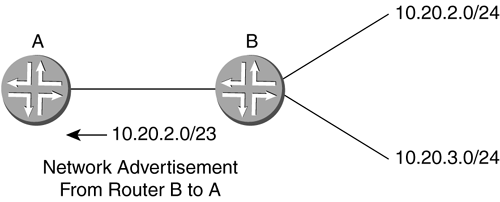
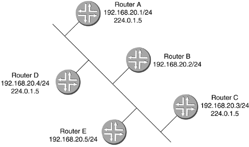
Using the preceding procedure, the binary for 189 is shown in Figure 2-26. A network address of 10.10.150.240 can be represented in binary as 00001010.00001010.10010110.11110000 . Figure 2-26. Converting from Decimal to Binary 2.2.3.2 Network Masks and Subnet MasksIP addressing has the primary purpose of uniquely identifying networks and hosts . To determine towards which networks a packet should be sent, an IP address is divided between a network number and a host number. Where this division occurs is called the network mask. A network mask is a bit-level representation of where the network number and host number are divided. The network mask is represented by /xx . The xx equals how many bits of the 32 available are used for the network portion of the address. The remaining bits are used for the unique host addresses of that network. Certain classes of network size used to exist. These networks were assigned to administrators based on their needs and could not be broken up. In Table 2-2, the address classes and their respective ranges are shown. The classes are A, B, and C. Class A networks are the largest and were therefore given to the largest companies. Class A networks use 8 bits of network mask ( /8 ) and can have over 16.7 million hosts! Class B networks are the next largest with 16 bits of network mask ( /16 ) and can have over 65,000 hosts. Class C networks have 24 bits of network mask ( /24 ) and can have 256 possible hosts. Class D addresses are reserved for multicast addressing. Multicast implementation will be covered in Chapter 14. Class E is an experimental IP space. Table 2-2. IP Address Classes
Notice that in Table 2-2, the 127.0.0.0 network is not shown. This is because the 127.0.0.1 address is set aside as a local address for devices' internal use. The original authority for assigning network addresses was the Internet Assigned Numbers Authority (IANA), although there are a number of registries today. These large network blocks were assigned by IANA upon request (today they are assigned by ARIN, RIPE, and APNIC). But if a company had 200,000 devices, it would have needed a Class A address. This Class A address would have over 16 million addresses unused. A system was devised to allow these large blocks of networks to be broken up into subnetworks. This allowed portions of blocks to be allocated properly based on need. The network mask of a subnetwork was a subnet mask because it was a subnetwork of the original- sized class. From this came the term classless routing. Classless interdomain routing (CIDR) is the implementation of the ability to shrink or grow the subnet mask based on how many hosts or networks are needed. The ability to properly size your subnet mask is called variable length subnet masking (VLSM). With four bytes of addressing space in an IP address, a subnet mask can be as large as a /30 , indicating that the address is for two devices on a point-to-point link. A single host address would be a /32 . When the binary is written out for a subnet mask, bits are counted from left to right to indicate what portion is used for the network. The binary can be written out broken into four groups of 8-bits each as shown in Figure 2-27. Figure 2-27. Sample Binary Subnet Mask with 30-Bit Address Figure 2-28 shows that if an IP network address is given with a /24 , that means that 24 bits of the address are used for the network portion, leaving 8 bits for the host portion. Figure 2-28. Sample Binary Subnet Mask with 24-Bit Address In the network mask in Figure 2-28, the network could have 256 potential host numbers, 0 to 255. 172.20.10.0/24 would range from 172.20.10.0 to 172.20.10.255 . The first number in a range is always used to identify the network as a whole. The last number of the network range is used to broadcast to all the hosts on that network (called a directed broadcast ). Since these two numbers cannot be used for hosts, then the two addresses must be subtracted from the pool of 256 available addresses leaving 254 available host addresses. The subnet mask can also be represented in decimal. Converting the address in Figure 2-28 from binary would give a subnet mask of 255.255.255.0 . 2.2.3.3 SubnettingIf a network administrator is to use the range of IP addresses assigned efficiently , the addressing range must be manipulable for different network implementations. For an office of 100 to 200 people, a /24 might be the appropriate network mask for that network, but what if it was a small office with only 20 to 40 people? Then there would a large number of wasted IP addresses in that range. VLSM allows for breaking a very large network range down into several parts as needed. If smaller networks are needed, then those parts can be broken down even further. If a new company wishes to implement an IP addressed network, it can request a block of addresses from its ISP. For this example, the ISP gives the company 10.10.0.0/21 . This range is from 10.10.0.0 to 10.10.7.255 . The subnet mask of /21 in Figure 2-29 denotes one network with 1,000 or more host numbers. The 1s in the mask represent the network bits and the 0s are the bits available for host addresses. Figure 2-29. Sample Subnet Mask with 21-Bit Address A single network of 1,000 or more devices is too large to use for one particular network. It can be broken down into usable subnetworks that are connected by routers to make more efficient use of the addressing space. The administrator can take this one block and split it by increasing the number of 1 subnet bits to the right. This will create two blocks from the original assigned network. The two networks would then be 10.10.0.0/22 and 10.10.4.0/22 . This can be most easily calculated using binary. 10.10.0.0/21 is represented as 00001010 00001010 00000000 00000000 The subnet mask is 11111111 11111111 11111000 00000000 The 10.10 portion of the network address is defined by the assigned mask. To split the 10.10.0.0/21 range into two networks, moving the subnet bit to the right by one bit allows for two network ranges. 10.10.0.0/22 is represented as 00001010 00001010 00000000 00000000 The subnet mask is 11111111 11111111 11111 1 00 00000000 10.10.4.0/22 is represented as 00001010 00001010 00000 1 00 00000000 The subnet mask is 11111111 11111111 11111100 00000000 This can be achieved because the 10.10.0.0/22 range includes the 20-second bit as either a 1 or a 0 because it is not part of the mask. To split the 10.10.0.0/22 once more into /23 s, the following would occur. 10.10.0.0/23 is represented as 00001010 00001010 000000 0 00000000 The subnet mask is 11111111 11111111 111111 1 0 00000000 10.10.2.0/23 is represented as 00001010 00001010 000000 1 0 00000000 The subnet mask is 11111111 11111111 111111 1 0 00000000 This process can be used many times to reduce the size of the network to create a range suitable for most purposes. If two routers are to be connected together with a point-to-point connection, the very small network between them only needs four addresses: the network number, the two router addresses, and the broadcast address. This would be represented as 10.10.0.0/30 . 10.10.0.0/30 is represented as 00001010 00001010 00000000 00000000 The subnet mask is 11111111 11111111 11111111 11111100 10.10.0.4/30 is represented as 00001010 00001010 00000000 00000 1 00 The subnet mask is 11111111 11111111 11111111 11111100 For the network address 10.10.0.0 , the two host addresses are 10.10.0.1 and 10.10.0.2 . The broadcast address is 10.10.0.3 . The next contiguous (adjacent or next in line) /30 network is 10.10.0.4/30 . The last digit of the network address is increased by one to find the next contiguous network (bold above). 2.2.3.4 AggregationAs the networks are broken down using the subnetting bits, many subnetworks will be created. Routers have to tell each other about these subnetworks. Too many subnetworks can take up a lot of time and bandwidth. In addition, keeping track of all of these networks can put a heavy processing load on the routers. In the same binary manner that larger network blocks can be subnetted to create smaller blocks, smaller blocks can be aggregated to form a larger network assignment. This is important when routers tell each other about the networks that they know about (called advertising ). Instead of many advertisements, if networks are aggregated together, there may need to be only one advertisement. Aggregation is achieved by moving the mask bit to the left, which reduces the number of 1s in a mask, creating a larger network range of host addresses. 10.20.2.0/24 is represented as 00001010 00010100 0000001 00000000 10.20.3.0/24 is represented as 00001010 00010100 0000001 1 00000000 The common subnet mask is 11111111 11111111 1111111 00000000 Figure 2-30 is an example of aggregation. If router B were to inform router A about the existence of its two attached networks, router B would advertise both networks as /24 s to router A. Router A would have two entries for router B's attached networks. If router B were to aggregate the two networks into a larger advertisement, then router A would only have to receive one entry ( 10.20.2.0/23 ), which would encompass both networks, instead of having to receive each /24 network individually. Figure 2-30. Aggregation of Networks Both network addresses in binary are the same to the twenty-third bit. Thus, they can then be advertised as 10.20.2.0/23 because that address range includes both the 0 and the 1 of the twenty-fourth bit. Chapter 8 explains routers advertising networks to each other in detail. This seems like a small example, but each of the /24 networks in Figure 2-30 could have been many smaller networks farther down. When networks are made up of thousands of contiguous subnets, aggregation becomes extremely important. 2.2.3.5 The IP PacketThe IP packet header contains information needed to transport the data from one host to another on a best-effort basis. IP has no mechanism itself to ensure that the packet is delivered. These functions are in different layers. IP header information primarily consists of address and fragment information. In the event an IP packet has to be fragmented , there has to be enough information to allow it to be defragmented at the appropriate time in its entirety. Different network types use different packet sizes. If an IP packet passes through a network that uses smaller packet sizes, the IP packet can be broken into fragments . An IP packet header has 20 required bytes and can have more if optional fields are used. Figure 2-31 is a representation of the required fields and the two last optional fields. Figure 2-31. The IP Packet Header Fields The 4-bit version (V) field informs the receiver of the version of IP being used. As stated earlier, the most common version is IPv4. The 4-bit IP header length (IHL) field describes the header length in 32-bit words (how many groups of four bytes are in the header). This is important if the optional fields are used so the receiver knows where the header ends and the data starts. The minimum is five (5 x 4 is 20 bytes minimum IP header). The 8-bit ToS field informs routers of precedence, delay, or service required. Speed (minimum delay) can be requested over reliability and so forth. ToS bits are used in DiffServ, allowing an administrator to configure different treatment of packets based on the ToS bits. The 16-bit total length (TL) field represents the total length of the IP packet. The 16-bit ID field aids in defragmenting packets. If packets need to be fragmented in transit, this ID can ensure that the receiver knows which fragments belong to which packets. The 3-bit flags (F) field informs a router if the packet can be fragmented. The 13-bit fragment offset (FO) field indicates where in the full packet a particular fragment fits. The first fragment would have an offset of 0. The 8-bit TTL field is decremented every time it is forwarded by a router. It has a maximum value of 255, allowing it to traverse 255 routing devices before it reaches the destination. When the TTL reaches 0, the packet is dropped. This keeps undeliverable packets from endlessly circling the Internet. The 8-bit protocol (P) field indicates the next upper-layer protocol used in the datagram. The 16-bit header checksum (HC) field represents the check on the packet header only. Since the packet header will change at every hop ( decrementing TTL) towards the destination, this has to be looked at every time the packet is forwarded. The 32-bit SA field is the IP address of the device that sent the packet. The 32-bit DA field indicates the IP address of the destination of the packet. The variable-length options (OPT) field can be used for control, measurement, source routing, and time stamping, among other things. The variable-bit padding (PAD) field is added if needed to ensure that the header ends after a 4-byte boundary. This will allow the TTL field to be accurate since it counts the number of 4-byte groups in the header. 2.2.3.6 TCP Versus UDPThere are different types of data to be sent and received across the Internet, and the various types of data need to be treated differently. TCP and UDP are at Layer 4 in the OSI model. The main difference between TCP and UDP is that TCP is connection-oriented for reliability and accuracy; UDP is connectionless and oriented for speed and consistent delay of transmission. During a file transfer, accuracy is important. The packet transmission can be bursty in nature: it can slow down or speed up and be received out of order. As long as all the packets are received, the file can be assembled . But if one packet is corrupted or lost, the file is quite often no good. This will require the receiving device to request the lost or corrupt packet again to ensure the complete file is received. This is connection-oriented communication. The sender and receiver set up communications before the data is sent to agree on the terms of transmission. These terms can be negotiations of such factors as how many packets are sent before an acknowledgment. Though video or music broadcasts on the Internet don't require perfect accuracy, they require orderly transmission. UDP packets are connectionless and are just sent out without the sender knowing if they are received. If a packet here and there is dropped or corrupted, it won't affect the overall quality of the data being sent. This is an advantage over TCP, which is connection-oriented. TCP would have the sender resend a packet that was dropped. This could make an audio or video transmission worse than if the packets were just lost. Order is more important than accuracy. TCP and UDP use the same port numbers to distinguish which of the upper-layer protocols the information is destined for. For example, FTP uses port 21, Telnet uses port 23, HTTP, or the World Wide Web, uses port 80, and SNMP uses port 161. Refer to www.iana.org/numbers.html for more information on port number assignments. When a device has several applications open and sending and receiving IP traffic at the same time, a differentiation has to be made between which IP packets belong to which upper-layer applications. That is where Layer 4 port numbers come in. They allow the TCP/UDP stack to forward traffic up the layers properly so that it gets to the appropriate application. TCP is very oriented on passing data reliably. TCP's header is larger than UDP's due to the sequence numbers and acknowledgments that make up the protocol's reliability functions. Sequence numbers have to be kept in order for the receiver to tell the datagrams apart for acknowledgment. Figure 2-32 shows the fields of a 20-byte-minimum TCP header. Figure 2-32. The TCP Header Fields The 16-bit source port (SP) field records the port from which the sending device sent the datagram. The 16-bit destination port (DP) field records the port that the data is being sent to on the receiver. The 32-bit sequence number (SN) field keeps the datagrams in order. The 32-bit acknowledgment number (AN) field is the next sequence number that should be expected to be received. The 32-bit data offset (DO) field is similar to a header length field. It describes where the header ends and the data starts. The 6-bit reserved (Res) field contains 6 bits all set to 0. They are for future use. The 8-bit control (Co) field controls the connectivity between the sender and receiver. These bits can inform the receiver that there is no more data from the sender, or either device can reset the connection with these bits. The 16-bit window (Win) field identifies the number of bytes starting with the byte in the acknowledgment field that the sender will accept. The 16-bit checksum (Chk) field is the result of a checksum being run on the header and data. The 16-bit urgent pointer (UP) field informs the receiver to offset the sequence number of the first byte of regular data if there is urgent data. The variable-length OPT field is not mandatory in the TCP header. This field can be used for functions such as setting buffer sizes for receiving large chunks of data. The variable-length PAD field is used to round out the header of a TCP datagram to the nearest 32-bit group (4 bytes) so the DO field is correct. UDP is very simple compared to TCP. Since UDP is connectionless, there is no need for connection-controlling information. Acknowledgments, sequence numbers, and the like are not needed. A UDP header is only 8-bytes long. Figure 2-33 illustrates the fields of a UDP header. Figure 2-33. The UDP Header Fields The 16-bit SP field records the port from which the sending device sent the datagram. The 16-bit DP field records the port that the data is being sent to on the receiver. The 16-bit length (Len) field specifies the length of the datagram header and data. The 16-bit Chk field that is the checksum run from the header and data of the datagram. 2.2.3.7 MulticastSo far, this chapter has discussed unicast and broadcast IP addresses. Unicast IP addresses send data to one host, whereas broadcast IP addresses send to all hosts in that network. What if you wish to send only to some of the devices on a particular network? This is what a multicast IP address does. When a group of devices wishes to receive data at the same time, a sender can send that data once to a multicast IP address to which the group listens. These IP addresses are in the Class D group of IP addresses, which are in the range of 224.0.0.0 to 239.255.255.255 . Often, a multicast address is applied to a device when a service requiring it is enabled. Video streaming is a type of service that can use multicast. When a device wishes to receive the video, it can listen in to the multicast IP address to which that particular video is being sent. In Figure 2-34 below, routers A, C, and D have enabled multicast. These three routers will listen to any IP packet that is sent to the destination IP address of 224.0.1.5 in addition to their normal unicast IP address in the 192.168.20.0/24 network. Routers B and E will not pay any attention to packets addressed to this address because they are not listening in for multicast addressing. They will only listen to their unicast IP address. Multicast is explained in detail in Chapter 14. Figure 2-34. Multicast IP-Enabled Network | ||||||||||||||||||||||||||||||||||||||||||||||||||||
EAN: 2147483647
Pages: 176
