2.1 Overview of the OSI Model
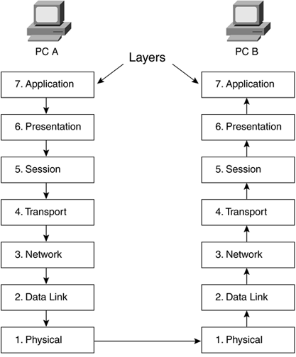
| There are many different parts of network systems that must interact to allow devices to communicate with each other. People can make each of those various parts in different companies across the world, but the parts must still function together. The ability of a program written in Seattle to work on a computer made in Boston and communicate over a network in Australia is achieved through strict adherence to published global standards. Networked devices use standards based on the OSI reference model. This model has different layers , requiring component creators to focus on compatibility with the standardized layers just above and below, and not with all the rest. This saves time and keeps applications from becoming too complex. Thus, engineers need only know the details of the layer that is their responsibility in order to create an application that will perform properly with other applications. 2.1.1 OSI Layers and FunctionsThere are seven layers in the OSI model. These layers are stacked vertically, passing information up and down to each other (Figure 2-1 illustrates these layers).
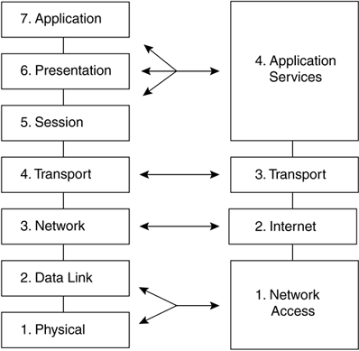
Figure 2-1. The OSI Model Network Standard Note The physical layer is one of the most important places to start troubleshooting. Hours upon end can be spent troubleshooting networks because a cable or connector was bent and not making contact. Standard troubleshooting techniques involve starting at the physical layer and working your way up. A device will communicate down the OSI stack, across the network, and up the OSI stack of the receiving device. This process ensures that as information is manipulated on leaving the sending device, those manipulations are equally copied in reverse order by the receiving device. In Figure 2-2, the application layer sends information down through the layers on PC A, across the network, to PC B, which will then send the information up the OSI stack to the application layer on the receiver. Once the application layer processes the data on the receiver, it can then be useful to the user. Figure 2-2. OSI Communications between Devices 2.1.2 IP SuiteIP was originally developed by the U.S. government for research. The original IP specification was four layers and was known as the DoD IP model after the U.S. Department of Defense, which developed the Internet for U.S. government agency communications. Owing to the widespread use of the model, it is known now as the Internet Protocol Suite. The four layers of the DoD IP model and how they map to the OSI reference model are shown in Figure 2-3. Layer 4 of the DoD model is the application services layer and represents all of the functions of the top three layers of the OSI model. Layer 3 of the DoD model is the transport layer, which is responsible for the same functions of acknowledgment and sequencing as the OSI third layer. Layer 2 of the DoD model is known as the Internet layer and is the responsible for IP addressing. Layer 1 of the DoD model combines the physical and data link layers of OSI and is known as the network access layer. Figure 2-3. The IP Suite ”A Common Protocol Implementation A good analogy of OSI stack system operation is the process of one person drafting and sending a letter to another. There are some predefined rules between the sender and the recipient that the sender would use to ensure the intended receiver was able to receive the letter, keep the pages in order, and understand what information the sender wished to convey. The purpose of drawing this analogy is to show that as things change at Layers 1 and 2, the upper layer information stays the same. In this way, data can be sent across various networks without being altered . How does this model allow for layered separation and why the letter analogy? This is how encapsulation works. Encapsulation is the process of taking one piece of data and adding a front (header) and a back (trailer). This allows for different devices to use only those layers they need through the process of chopping, packetizing, and framing the upper layer data in a standard format. The following details how data would be transmitted according to this analogy.
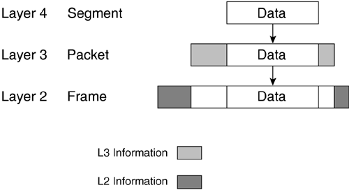
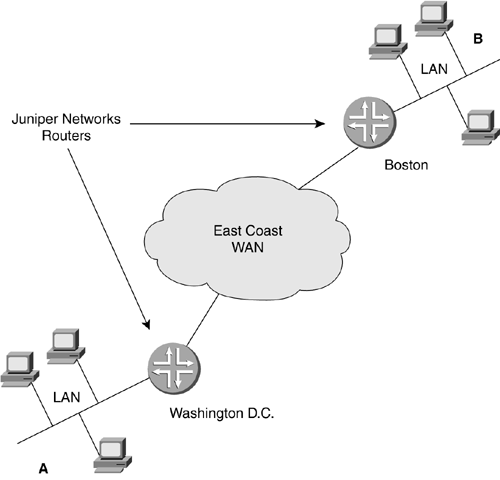
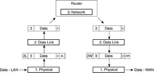
Just as in the analogy above, Layers 1 and 2 can be changed several or even many times as the packet makes progress towards the destination. Once the destination has been reached, Layers 3, then 4 can be stripped by the receiver and the return receipt signed (Layer 5) to present the data to the reader, ending the communications channel. The letter inside, the envelope, and the destination-addressing scheme are never altered by the lower two layers' independent processes. The truck and the airplane transportation are not affected by what is in the envelope. The Layer 3 address would be looked at to forward the letter appropriately, but it would not be altered. This is the layer separation that allows the different components to work together as long as the standards are adhered to. 2.1.3 Encapsulation at the Lower LayersNetworking in general is predominately focused on Layers 1 to 4, or the lower layers (with the upper layers consisting of 5 to 7). When discussing networks or systems, quite often the terms upper layer and lower layer are used. Layers 1 to 4 are the layers that Juniper Networks routers use to accomplish the task of getting data from point A to point B. Although most routing functions do take place on Layer 3 at the network address, Layer 4 TCP/UDP ports can be used for giving preference or forwarding decisions for packets. Components of Layers 1 to 4 accomplish network transmission and reception of the upper-layered data. You can think of Juniper Networks routers as a very fast transportation system. Figure 2-4 illustrates the encapsulation of data as it moves down the layers for transmission. As the data moves down the stack, each layer adds information for the corresponding layer on the receiver. At Layer 4, a segment of data is created, then encapsulated in a Layer 3 network packet, which gets wrapped in a Layer 2 data link frame, then transmitted on the physical Layer 1. Figure 2-4. Data Encapsulation In the receiving stack each layer reads the necessary information for its particular layer, strips that information off, and forwards the data upwards. 2.1.4 Network DevicesDifferent network devices were created to aid in the transmission of data at the different layers. At the data link layer, bridges and switches are used. Bridges and switches work at Layer 2. They can connect various physical media as long as the data link protocol is the same. At Layer 3, the network layer, routers from companies such as Juniper Networks are used. Routers can connect different data link networks as long as they use the same network layer protocol. Each of these devices forwards data based on the standards of the layer on which they work. Most network devices and technologies can be thought of as part of one of two groups, local or wide. Local-area network (LAN) devices usually connect users centered in a close geographical area. These devices are usually switches or small-access routers. WAN devices typically connect groups of LAN devices over long distances. For the most part, a Juniper Networks router is a device that can connect groups of LANs and WANs together. Since the OSI layers work together, different data link layers can be used to forward a single type of network layer data. Going back to the example of the letter, the envelope can travel in a truck, then an airplane, then in a truck again. The truck is used locally and the airplane transports the letter across long distances. So too can networking use different methods of transportation. It is very typical for data to move from LAN to WAN to LAN in order to get from the sender to receiver. In Figure 2-5, there is a sender A and a receiver B. The data has to go through the LAN in Washington D.C. to get to the WAN that will allow it to be transferred up the East Coast WAN to the LAN in Boston. A Juniper Networks router connects the LAN to the WAN. One port of the router is connected to the LAN and one is connected to the WAN. In addition, the cloud representing the WAN could be made up of many Juniper Networks routers in a network. Juniper Networks has developed a wide variety of ports, allowing them the ability to forward data from and to LANs through WANs for many situations. Figure 2-5. LAN-WAN-LAN Communication Bridges and SwitchesA bridge is normally used to connect two groups of similar data link devices, such as PCs on Ethernet. A bridge can divide an overloaded LAN network in two groups, managing the communications between them. This allows the LAN to continue to function seemingly as a single group . As the LANs get larger, more ports are needed on a bridge to divide the LAN into more groups. Eventually each data device is able to have its own port; the bridge is then called a switch because it switches data between the ports. A switch greatly increases a LAN's communication efficiency. Every device has its own port ”it's own private connection. With every device having a dedicated, rather than a shared, connection, a device is able to send and receive more data through LANs and ultimately through WANs. The switch can manage the communication between LAN devices much more quickly and efficiently than the devices themselves when all of them are essentially trying to talk at the same time. Note A bridge that connects dissimilar data link devices is called a translational bridge and one that connects similar data link devices is properly called a transparent bridge. Other types of switches operate in the WAN. These use protocols like ATM or frames from a Frame Relay network. These are the types of switches in the middle of large networks to which Juniper Networks routers are connected in order to pass data. 2.1.5 RoutersRouters work at the network layer. They look at the destination address of the IP packet and forward the packet in the right direction. Juniper Networks routers can connect different types of LANs and WANs. In addition, Juniper Networks routers can connect different types of WANs together on a very large scale. In Figure 2-6, a Juniper Networks router takes in a frame from the Layer 2 data link LAN protocol (2L), then strips off the Layer 2 LAN information to look at the Layer 3 network information. The Layer 3 information must be looked at to determine where the data must be sent, but it is not manipulated or changed; it is merely observed . This is called a Layer 3 lookup because the device is looking at the Layer 3 protocol address to determine the correct path to forward it upon. Higher-layer information is usually not looked at. The router then decides in which direction (out of which port) to forward the information, changes any Layer 3 information needed (e.g, TTL), adds Layer 2 WAN (2W) information, encapsulates the packet, and the router sends the data on its way. Figure 2-6. Layer 3 Lookup |
EAN: 2147483647
Pages: 176

