Basic MEL Controls
| This section shows you how to use MEL scripting to create a basic character window. How to write a MEL command in the Script Editor is described in detail, as well as where you can store and access your MEL code in Maya. You learn how to create several useful controls for your character, including buttons, sliders, and check boxes. In addition, you learn several layout commands that enable you to place your MEL controls in a variety of positions within your character window. Getting Started with MELMEL scripting facilitates everything you do in Maya. Whenever you create, modify, or transform something using menu commands or tools, Maya is performing the action through MEL commands in the background. Normally you don't see this happening, although you may occasionally notice some MEL results that Maya writes out to the Feedback field of the command line. To see what Maya is doing, you must open the Script Editor by clicking its icon in the lower-right corner of the interface, and look in the History field (see Figure 6.2). 6.2. Use the gray History field in the Script Editor to view MEL commands that occur while you are working in the Maya interface.
The Script Editor contains two fields. The top, gray-colored section is the History field, and the bottom, white-colored section is the Scripting field. The History field is where you can see what MEL code Maya is running when you do something in the interface. In a blank scene, for example, create a primitive NURBS sphere by choosing Create, NURBS, Sphere. Notice that a line of code is written to the History field that looks like this: sphere -p 0 0 0 -ax 0 1 0 -ssw 0 -esw 360 -r 1 -d 3 -ut 0 -tol 0.01 -s 8 -nsp 4 -ch 1; This is the MEL command that Maya uses to create a NURBS sphere. The command itself is sphere, followed by several letters preceded by dashes, called flags, and ending in a semicolon. The flags are setting the options on the sphere command, which you normally specify when working in the interface within an options box. For instance, the -p flag is specifying the sphere's pivot-point placement. The three numbers after the flag represent the translation values of the sphere in 3D space, so that 0, 0, 0 specifies placement at the global origin. The -ax flag sets the axis of the sphere to point up in Y. In addition, the -ssw flag sets the start sweep of the sphere to 0 degrees, and the esw flag sets the end sweep to 360 degrees, which creates a full sphere. If the -esw flag were set to 180 degrees, only half a sphere would be created. Some flags require numeric values, whereas some are switches that are set either on or off, and others require a string of text. With the sphere still selected, type a value of 5 into its Y translation channel. A line of MEL code should be written in the History field that looks like this: setAttr "nurbsSphere1.translateY" 5; The setAttr MEL command sets an attribute to a particular value. Notice that the syntax of the command is written as all lowercase letters, except the first letter of the second word, which is capitalized. This is true of all MEL commands. They always start lowercase, with the first letter of each additional word being capitalized, and no spaces between the words in the name of the command. If there were a MEL command named My Big Command, for instance, it would be written as myBig Command. Keep this in mind when you are writing MEL code, because any mistake in the capitalization results in an error message. The History field proves an invaluable resource to find out what MEL commands are used by Maya to do specific tasks. To actually input a MEL command, you must type it in the command line, or type it in the Scripting field inside the Script Editor. The command line is mainly used to input a single command, whereas the Scripting field is used for typing in multiple commands. In the Script Editor, the regular Enter key on the keyboard enables you to create multiple lines of code, whereas pressing the Enter key on the numeric keypad actually runs all the commands. As an example, highlight the setAttr command that occurred earlier in the History field for moving the sphere in Y, and hold down the middle mouse button to drag it down into the Expression field. When the line of code is in the Scripting field, change the Y value in the line of code. Also highlight the line of code to copy it by pressing Ctrl+C, press the regular Enter key to go to the next line, and paste the code by pressing Ctrl+V. Change the second line of code to specify a translation value in X, rather than Y. Your two lines of MEL code should look similar to this: setAttr "nurbsSphere1.translateY" -3; setAttr "nurbsSphere1.translateX" 10; When your two lines of code are complete, press the Enter key on the numeric keypad to run it (you can also press Ctrl +Enter). If the code contains no errors, it passes from the Scripting field to the History field, and the sphere should move in Y and X to whatever values you specified in your two setAttr commands. Many times when researching MEL commands in the History field, you won't know what a particular flag means. A MEL command named help gives you more information on any MEL command. Just type in help, followed by the name of the MEL command. To get help on the sphere command, for instance, type the following in the Script Editor: help sphere; Running this code results in a summary of the sphere command in the History field that looks like this: Synopsis: sphere [flags] [String...] Flags: -e -edit -q -query -ax -axis Length Length Length -cch -caching on|off -ch -constructionHistory on|off -d -degree Int -esw -endSweep Angle -hr -heightRatio Float -n -name String -nds -nodeState Int -nsp -spans Int -o -object on|off -p -pivot Length Length Length -po -polygon Int -r -radius Length -s -sections Int -ssw -startSweep Angle -tol -tolerance Length -ut -useTolerance on|off All the flags for the sphere command are listed, including their long and short names, as well as some clues as to how each flag should be set. The -d or -degree, for instance, requires an integer or whole number. The -n or -name flag, on the other hand, requires a text string in double quotes. The -o or -object flag is a Boolean type of on or off switch, which can be written as true or false. If a command is pretty simple, like the sphere command, the basic help command may be adequate for understanding how to use it. However, you may require more information to effectively use some commands. To get more information about a command, you can use a flag on the help command. To get more detailed information on the setAttr command, for example, type the following: help doc setAttr; Running this code opens an Internet Explorer web page with detailed information on the setAttr command. An explanation on how to use the command is given, as are additional details about each flag. One of the most important things on this page is the example code at the bottom of the page. You can copy and paste the code into the Script Editor to run it, and view a simple example of what the command does. This is a good way to start using a command. Many times you can modify the code given in the example by just adding your own content to customize it for your own purposes. Another useful thing at the bottom of the page is a list of commands related to the setAttr command. One thing you may have noticed is that some of the basic tasks you do while working in the Maya interface do not produce any MEL commands in the History field. Changing tools, for instance, does not produce any MEL code. To force Maya to write the code for these tasks to the History field, on the Script Editor's menu bar, you must choose Script, Echo All Commands. This causes Maya to write everything it does to the History field. Changing tools, for instance, produces the changeToolIcon command in the History field when Echo All Commands is turned on. Echoing all the commands should only be turned on when you need it, however. Doing regular tasks, such as creating a sphere, produces several more lines of code than previously produced. While working in a complex scene, forcing Maya to write everything to the History field will considerably slow down your system, so it is best to keep Echo All Commands turned off most of the time. Also in the Script menu, make sure Show Line Numbers is turned on. This is useful for when you are debugging multiple lines of MEL code. If you receive an error message when trying to run your code, Maya writes to the History field what line number the error is on. Then you can count down to more quickly identify the error, and correct it. One other way you can get help on MEL commands is to use the MEL Command Reference. Access this on the top menu bar by choosing Help, MEL Command Reference. This opens an Internet Explorer page that contains all the available MEL commands in Maya. The commands are grouped alphabetically by name, by category, and as a complete list. If you click the letter S link, you will see all the MEL commands that begin with an S. Clicking the setAttr command brings you to the same page that opened when you previously typed in the command help -doc setAttr. Go back to the previous page, and scroll down to view all the categories of MEL commands, such as Animation, NURBS, and Windows. Clicking the NURBS link, for instance, brings you to a page that lists all the MEL commands that relate to NURBS surfaces. Using categories is a good way to see whether Maya has a particular MEL command for doing a specific kind of task. If you can't find a MEL command for a particular task, chances are you can't do it in Maya at all, or it can only be done through more complicated programming. Sometimes code for which you cannot get any documentation appears in the History field. For instance, try looking up the changeToolIcon command that came up earlier when you turned on Echo All Commands. You won't find this command listed anywhere in the MEL Command Reference. To find information on this command, you must use the whatIs MEL command. Type the following into the Scripting field: whatIs changeToolIcon; The whatIs command returns either the word Command, for a MEL command, or it tells you it is something else, and where the script is located. The output of the preceding command states that the changeToolIcon command is a procedure found in the Scripts folder that Maya runs when the program is launched. This illustrates an important point to remember when working in the Script Editor; everything in Maya is not done strictly through MEL commands. Hundreds of other scripts are being used in addition to the standard MEL commands. The whatIs command can help you to track down these other scripts, so that you can open them to find out how they work. Scripting a Simple Control WindowTo begin creating your MEL-scripted character controls, you must first create a floating window to hold all the controls. You must use two commands to make a custom character window. The command for creating a window is window, and the command for actually displaying the window in the Maya interface is showWindow. If you look up the window command in the MEL Command Reference, you can see all the flags you can add to the command. Some useful flags are -t or-title to give the window a name on the title bar, and -wh or-widthHeight to set the size of the window. Type the following into the Scripting field: window title "My Window" widthHeight 300 200; showWindow; Running this code should create a 300-by-200 pixels floating window with My Window on the title bar (see Figure 6.3). You can move, minimize, and scale your custom window just like any other floating window in Maya. Close the window by clicking the close icon on its title bar. 6.3. You must first create a basic window before you can create any other MEL-scripted character controls.
Notice that the code you wrote for the window passed from the Scripting field to the History field in the Script Editor. This is fine if you are only typing in a command once. If you are gradually refining and testing the code, however, there is a more efficient way to run the code. Just highlight the code in the Scripting field that you want to run, and press the Enter key on the numeric keypad. This keeps the code from passing out of the Scripting field. Use this technique as you gradually add controls to your custom window. Adding Buttons and SlidersTo add some controls to your window, make sure you copy the window commands you ran earlier from the History field back into the Scripting field. Also rename the sphere in your scene from its default name to a simple name such as Sphere. Keep in mind that all the lines of code you add for the controls should be written between the window and showWindow commands. Before adding controls to a window, you must tell Maya how you want the controls to be placed. This is called a layout command, the simplest one being columnLayout, which stacks the controls vertically, flush left, in a single column. After the columnLayout command, you can start placing some controls, which will be buttons. The command for creating a button is just button, and there are a few important flags that you should include with the command. These include the -l or-label flag, which is used to display a name on the button, the -w or -width flag to set the size, and the -c or -command flag to make the button run a command. Buttons are best used for doing one particular thing, such as selecting an object. To find out what MEL command to use for selecting the sphere, just do it and look in the History field. To make the select command work in the button, you must put double quotes around the entire command. To make a button that selects the sphere, for example, type the following into the Scripting field: window title "My Window" widthHeight 300 200; columnLayout; button label "Select" width 100 command "select r Sphere"; showWindow; Note MEL Syntax in Maya 5: When writing MEL code, you can use the regular Enter key to break the code up into multiple lines, and use the Tab key to indent in order to make the code easier to read. Maya reads the code as one command until it reaches a semicolon. However, in Maya 5, if you break a text string into multiple lines, you will get an unterminated string error message. A text string is a line of code within double quotes, such as in the "Select" button command after the -c flag. In most cases, avoid breaking a string into multiple lines. If you must break a string into multiple lines, use a \ symbol at the end of the broken line to keep from getting an error message. Keep in mind that in the script examples shown in this chapter, continuous lines of code that are wrapped to the next line due to formatting are symbolized by a bold arrow. These should be written in Maya as one line, and do not require the \ symbol. All the correctly written MEL code for the examples in this chapter can be found on the download site, which can be opened in a text editor, and copied directly into your script editor for testing. Running this MEL code should create a window with a single Select button that selects the sphere when you press it. After you have one button made, it is easy to make additional buttons by just copying and pasting. Copy and paste to create an Unselect button, and drag a selection box in an empty area of the perspective view to clear the selection. Use the History field to get the command for unselecting the sphere, which should be a select command with a -cl or -clear flag. Copy the command from the History Editor to the -c flag of the new button command. Your code should look like this: window title "My Window" widthHeight 300 200; columnLayout; button label "Select" width 100 command "select r Sphere"; button label "Unselect" width 100 command "select -cl"; showWindow; After running the code, test both buttons to see how they work (see Figure 6.4). You may also want to look up in the MEL Command Reference the command for selecting objects, and make a note of the other flags available for this command. There is a flag, for instance, that enables you to toggle the selection. By being familiar with the available flags for a command, you will be able to customize your controls for exactly what you need them to do. 6.4. Place basic selection buttons as the first controls in your custom MEL window.
The second MEL control you want to add to your window is a basic slider. Sliders are best used for animating attributes smoothly over time. The command for creating a basic slider is attrFieldSliderGrp. The -l or -label flag also applies to this control, as do the -min and -max or the minValue and maxValue flags to set the minimum and maximum limits of the slider, the -cal or columnAlign flag, which sets the label flush left, and the -at or -attribute flag to connect the slider to an attribute. To create a slider that makes the sphere move up and down, specify Sphere.ty in the -at flag. Double quotes are not needed to specify an attribute. Notice in the example that you can also use the short version of the channel names in your MEL commands. Your MEL code should look like the following: window title "My Window" widthHeight 300 200; columnLayout; button label "Select" width 100 command "select r Sphere"; button label "Unselect" width 100 command "select -cl"; attrFieldSliderGrp label "Move Sphere Up and Down" minValue 20 maxValue 20 columnAlign 1 left attribute Sphere.ty; showWindow; Running this code should create a slider that translates the sphere up and down 20 grid units in Y. To make another slider control the movement of the sphere from side to side, copy and paste the first slider, and just change the name and attribute. Notice that when setting the limits on sliders, there is a minimum and maximum setting, but not a default setting. This is because MEL sliders are not constraining the object, but just an interface for accessing the attributes of the objects. The default setting for an attribute is whatever the channel is already set to. If you select the sphere and translate it in Y manually with the Translate tool, the slider updates accordingly. Notice that the object can actually be moved beyond the slider limits. You can also set keys on the slider by right-clicking its label and choosing Set Key, but the keys are not set on the slider. The keys actually go directly on the attribute the slider is controlling. One other thing you might want to do is make the buttons and sliders scale with the window size. Do this by adding an -adj or -adjustableColumn flag to the columnLayout command. In addition, add an -adj flag to each of the attrFieldSliderGrp commands. Your MEL code should look like this: window title "My Window" widthHeight 300 200; columnLayout -adjustableColumn true; button label "Select" width 100 command "select r Sphere"; button label "Unselect" width 100 command "select -cl"; attrFieldSliderGrp label "Move Sphere Up and Down" minValue 20 maxValue 20 columnAlign 1 left -adjustableColumn true attribute Sphere.ty; attrFieldSliderGrp l "Move Sphere Side to Side" minValue 20 maxValue 20 columnAlign 1 left -adjustableColumn true attribute Sphere.tx; showWindow; After you have run this code, try resizing the window by dragging one of its edges. The buttons and sliders should scale with the window (see Figure 6.5). Although the buttons scale completely with the window, there are limits on how a slider can stretch. Because of the set width of the slider itself, it only moves in relation to the text label, instead of actually scaling larger or smaller. 6.5. Set command flags to make your basic buttons and attribute sliders scale with your window.
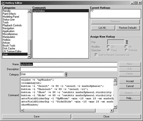
Where to Store Your MEL CodeUntil this point, you have just been using the Script Editor to work on your MEL code. This gives you the advantage of having access to the History field for copying commands and reading error messages. You can save your MEL code in the Script Editor by highlighting the code and choosing File, Save Selected. However, saving MEL code as a MEL script in the Script Editor is usually reserved for more complicated scripts. If you are just writing a few lines of code to create a control window, you can store the code in other places for easy access. One place that you have already used in previous chapters is the shelf. Highlighting the code in the Script Editor and using the middle mouse button to drag it onto the shelf is an easy way to store your code. Doing this creates a shelf button that you can click to run the MEL code, and open your control window. To edit MEL code placed on the shelf, click the drop-down arrow button to the left of the shelf, and choose Shelf Editor. Inside the editor, choose the Shelves tab to pick the shelf that contains your MEL code, and then go to the Shelf Contents tab to pick the button to edit. If you drag the code written previously for controlling a sphere to the shelf, for example, choose the code in the list that starts with a window command. Type in a more descriptive label, such as "This opens my sphere control window," that will show up if you place your cursor over the button. Also give the button a short icon name, such as Win1. As an option, you could click the Change Image button to assign a custom image to your button. Create the image in a paint program, such as Photoshop, and save it as a 35-by-35 pixels bitmap image. Make sure you place the image in the Icons folder with all the other Maya icons so that it will be there when you click the Change Image button. To edit the MEL code in your custom button, with it highlighted in the shelf editor, choose the Edit Commands tab. Add code as needed to create additional controls, and click the Save All Shelves button. A similar way to store, edit, and access your MEL code is to assign it to a hotkey. Open the Hotkey Editor by choosing Window, Settings/Preferences, Hotkeys (see Figure 6.6). Click the New button to create a new hotkey. Then type in a name, short description, and make sure the category is set to User. Place your MEL code in the hotkey by dragging it with the middle mouse button to the Command field. When you are done, click the Accept button. This creates the contents of the hotkey, but doesn't assign it to a particular key. You must first query a key to see whether anything is already assigned to it. Try typing in F7 to the Key field, and click Query. Chances are this key has not been assigned to anything. To assign it, just click the Assign button with the Press Direction turned on. If F7 is already assigned to something, try adding a Ctrl or Alt modifier. When the key is assigned, click the Save button, and close the Hotkey Editor. Then activate one of the views, and press your new hotkey to open your control window. 6.6. Copy your MEL code into the Hotkey Editor to assign it to open your window when you press a hotkey.
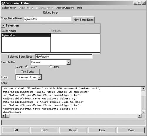
A third place to store, edit, and access your MEL code is in a marking menu. Marking menus can be called up by holding down a key while pressing a mouse button and moving the cursor. The most common example of this is to hold down the Spacebar to access menus in the hotbox. Open the Marking Menu Editor by choosing Window, Settings/Preferences, Marking Menus. Click the Create Marking Menu button, and use the middle mouse button to drag your MEL code over one of the empty boxes. A MEL button will appear in the window, which you can right-click to edit the label or image. When your MEL code is in the window, give the marking menu a name, and click the Save button. The name you gave your new menu should come up in the Marking Menu Editor list. You must then assign the new marking menu to either a hotkey or to the hotbox. Try assigning it to a space in the hotbox by choosing Hotbox in the Settings drop-down list. Set the Region to Center, and the Button to Left. Click the Apply Settings buttons, and close the Marking Menu Editor. To run your code, just hold the Spacebar down and click with your left mouse button on the middle of the Hotbox menus. The name for your menu should appear. Just drag your cursor over it to open your control window. Clicking the same region with the middle or right mouse button gives you access to a different menu. Keep in mind that all these methods shown for storing your MEL code are limited to your local machine. Code being stored on a shelf, in a hotkey, or in a marking menu is being stored with the rest of your preferences in a Maya directory created for your login on the C: drive. It is not being stored with your character scene file that you have been building, so it won't be available if you open your character on a different computer. You would have to copy those preferences files over to the same directories on the other machine to use your MEL character controls. Or, to save MEL code with a particular scene file, you must create a script node in the Expression Editor. Open the Expression Editor, and choose Select Filters, Script Node. First type a name for your script node. Then just use the middle mouse button to drag your MEL code into the white Scripting field, and click the Create button. You should see the name of your script node come up in the list of script nodes (see Figure 6.7). After your MEL code has been stored in a script node, it will be saved with your scene file. Click the Test Script button to run your MEL code and open your control window. Keep in mind that if you make any changes or additions to your MEL code, it is not enough to just click the Test Script button. You must also click the Edit button to have the changes saved into the script node. Otherwise, you may lose all of your edits when you open your scene file later. 6.7. Creating a script node in the Expression Editor enables you to save your MEL-scripted window with your scene, so it is always available.
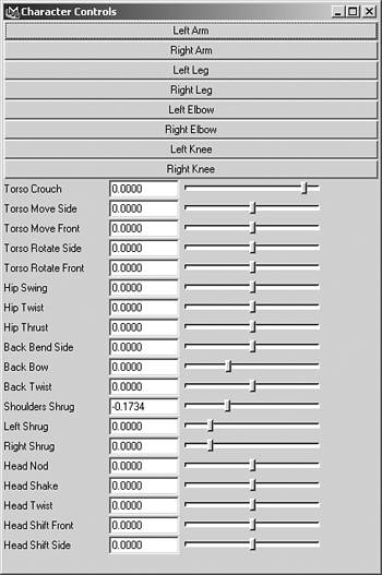
Other Useful ControlsWhen writing your MEL code, it is a good idea to add comments to remind yourself, or anyone else who may use your code, what the script does. A comment is a text string that Maya does not run as part of the code. In MEL, lines in a script can be commented out by placing two forward slashes (//) in front of each line. For instance, you may add comments at the beginning stating who wrote the script, and describing the purpose of the script. You can also add comments throughout the script to describe how each section works. Here is an example of adding comments at the beginning of your script: //This MEL script by Chris Maraffi creates a basic character window: window -t "Character Controls" wh 400 600; columnLayout adj true; //This section creates selection buttons: button -l "Left Arm" -c "select -r LtArm"; button -l "Right Arm" -c "select -r RtArm"; button -l "Left Leg" -c "select -r LtLeg"; button -l "Right Leg" -c "select -r RtLeg"; In addition to commenting out a whole line, you can comment out specific sections of text by surrounding it with an asterisk (*) and forward slash (/), as follows: Your MEL code /*comments*/ Your MEL code You may also want to display some text in your control window to give the user some additional headings or instructions for how to use the controls. You can do this by using a MEL text command. The main flag to use with this command is a -l or -label flag, where you can specify the text that you want to display by placing it in double quotes. Other flags you may want to use are the -al or -align flag, -w or -width flag, and -fn or -font flag. Here is an example of using a text command to create a heading for the buttons in your script: window -t "Character Controls" wh 400 600; columnLayout adj true; //This section creates selection buttons: text l "Selection Buttons:" -align left -w 400 - font "boldLabelFont"; button -l "Left Arm" -c "select -r LtArm"; One way to make your control window more organized is to add separators. A separator is a graphic line that can delineate sections of your window for specific controls. The main flag to use is the -w or -width flag to set how much space in the window the separator will take. Other flags you may want to use are the -st or -style flag, and the -hr or -horizontal flag. These flags set the graphic style of the separator, and set whether the separator should be horizontal or vertical. Here is an example of how you could add separators between your controls in a column layout: button -l "Left Arm" -c "select -r LtArm"; separator width 400 style "double" horizontal 1; attrFieldSliderGrp -l "Torso Crouch"-min -10 -max 1 cal 1 left adj true -at UpperBody. Another control you will want to add to your character window is a Boolean style on-off switch. The best MEL command for doing this is the checkBox command. You can use a check box to turn the visibility of objects on or off, or to control whether an IK solver is on or off. Another use is to toggle switches in the interface, such as turning the Auto Keyframe button on or off. The two flags that make the check Box command work are the -onc or -onCommand, and -ofc or -offCommand. These two flags run separate commands when the check box is clicked on or clicked off. You should also use the -l or -label flag, and the -al or -align flag in the command. To create a check box for hiding your character's skin, for instance, you should set it to control the visibility of the group node parent of your models. Do this by using a setAttr command to set the Skin.visibility channel to either 1 or 0. Place the command at the beginning of your character window script, right after the layout command, and before the selection button commands. Your final checkBox command should look similar to this: checkBox label "Hide Skin" align left onCommand "setAttr Skin.v 0" offCommand "setAttr Skin.v 1"; An alternative to using a check box for controlling objects is to use radio buttons (see Figure 6.9). Although a check box is still the best control for running two different commands, radio buttons are used when you want to run three or more different commands. This is because radio buttons enable you to have more than just two states. For instance, you can have three radio buttons that toggle the visibility of your character's skin from visible, to a template state, to hidden. Keep in mind that, once initialized, at least one radio button is always checked on. The command used to create radio buttons is the radioButtonGrp command. Using the flags, you set the number of radio buttons, label the group and individual buttons, and set commands for each button when it is checked on. To create radio buttons to control the visibility and template state of your character's skin, for example, you must write a command similar to the following: radioButtonGrp -numberOfRadioButtons 3 -label "Skin Visibility" -labelArray3 "Show" "Template" "Hide" columnAlign 1 left -onCommand1 {"setAttr Skin.v 1; toggle -state off -template Skin"} -on2 {"setAttr Skin.v 1; toggle -state on -template Skin"} -on3 {"setAttr Skin.v 0; toggle -state off -template Skin"}; 6.9. Radio buttons are similar to check boxes, but run multiple commands, and are always turned on.
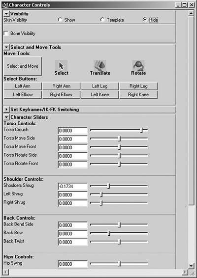
Notice that there are multiple commands within each -onCommand flag. Each flag is setting the skin's visibility and toggle state. To run multiple commands in a flag, you must place double quotes and curly brackets around all the commands. This keeps Maya from reading the semicolons within each flag command as the end of the radioButtonGrp command. Otherwise, you will receive an error message. Use the -cal or -columnAlign flag to set the control flush left. In most cases, it is best to assign controls to specific single attributes, such as assigning a slider to the Hips.rz channel or the UpperBody.ty channel. Some controls, however, can be assigned to multiple grouped attributes, called vector attributes. One such control is a field group, which is created by using the attrFieldGrp command. This command creates three fields that are connected to a vector attribute with the -at or -attribute flag. Instead of specifying a particular translate channel to control, for instance, you just specify all the translate channels. Then each field is connected to each translate channel, and the user can control the channels by inputting values into the fields. Right-click the label to set keys on all the translate attributes, or right-click a single field to set a key on only that particular attribute. For example, such a control for the left arm box would be written like this: attrFieldGrp label "Translate Left Arm Box" columnAlign 1 left attribute LtArm.translate; You can create tool buttons in your MEL control window by using the toolCollection and toolButton commands. You must use two flags with the toolButton command: The -t or -tool flag sets the active tool, and the -ti1 or -toolImage1 flag sets the tool icon to display. Another useful flag is the -sl or -select flag to have a particular tool selected when the window opens. You also can use the -iol or -iconOverlayLabel flag to add a text label over the tool icon. Your toolButton commands should look similar to the following: toolCollection; toolButton -tool selectSuperContext -select -iol "Select" -width 60 -toolImage1 selectSuperContext "aselect.xpm"; toolButton -tool moveSuperContext -iol "Translate" -width 60 -toolImage1 moveSuperContext "move_M.xpm"; toolButton -tool scaleSuperContext -iol "Scale" -width 60 -toolImage1 scaleSuperContext "scale_M.xpm"; toolButton -tool RotateSuperContext -iol "Rotate" -width 60 -toolImage1 RotateSuperContext "rotate_M.xpm"; An alternative to creating individual Transform tool buttons in your control window is to make a Move Icons button that activates the Show Manipulator tool. This will ultimately save you time when animating, because the Show Manipulator tool enables the active transform to change automatically when you select each icon. For it to do this, you must first assign a default object manipulator to each of your icons. To do this, select the icon, choose Modify, Transformation Tools, Default Object Manipulator, and choose a manipulator. The manipulator you choose should fit your icon. For instance, the arm boxes should only be assigned a move manipulator, because they are never rotated or scaled. The Head box, on the other hand, should only be assigned a rotate manipulator, because it is never translated or scaled. Icons that need to be both moved and rotated should only be assigned the move-rotate-scale manipulator. This option, however, is not available in the menu. To assign this manipulator, turn on Echo All Commands in the Script Editor, and assign a default move manipulator. In the History field, notice the code assigning the manipulator uses the setDefaultManip command, with a setting of 1. The rotate manipulator is a setting of 2, and the scale manipulator is a setting of 3. If you input this command with a setting of 4 in the Scripting field, the move-rotate-scale manipulator is assigned. Create a shelf button containing the code for easily assigning the move-rotate-scale manipulator to your icons. Your code should look like this: setDefaultManip 4; After you assign default object manipulators to all your icons, make a Move Icons button that activates the Show Manipulator tool. The MEL command to activate a particular tool is the setToolTo command, as follows: button -l "Move Icons" -c "setToolTo ShowManips"; Using Additional LayoutsIf you keep adding controls in your window, eventually you will run out of screen space. Using only column layout will not give you access to controls that are beyond your window's edge. To be able to access those controls, you must add a scrollLayout command. This command creates a scrollbar whenever your controls go beyond the size of your window. Because the scroll layout overrides the adjustable scaling of your controls with the window, you can remove the -adj flags if using scroll layout. To add a scrollbar to your window, just add the command before your columnLayout command like this: window -t "Character Controls" wh 400 600; scrollLayout; columnLayout; button -l "Left Arm" w 200 -c "select -r LtArm"; If you want to place your controls horizontally, rather than vertically, you use the rowLayout command. This layout enables you to specify the number of columns, using the -nc or -numberOfColumns flag, for placing controls in a row. For instance, you would create four columns to place four buttons in a single row. You must use the -cw4 or -number OfColumns4 flag to set the width of each column. The MEL code to do this should look like this: window; rowLayout -nc 4 -cw4 60 60 60 60; button -l "Left Arm" -c "select -r LtArm"; button -l "Right Arm" -c "select -r RtArm"; button -l "Left Leg" -c "select -r LtLeg"; button -l "Right Leg" -c "select -r RtLeg"; showWindow; To make multiple rows using this command, you must stack the rows with a columnLayout command. For this to work correctly, however, you must also use a setParent command. Whenever you use multiple layouts within a single window, you must assign the layouts in a hierarchy structure. This tells Maya how each layout relates to all the others. The setParent command enables you to assign a layout to a parent layout. This is often done by writing setParent..; after the contents of each child layout, which assigns the child to the next highest layout in the window. If you don't set the parenting correctly, you will get an error message stating there are too many children. To set the parenting for multiple rowLayout commands, for example, your code should be similar to the following: window; columnLayout; rowLayout -nc 4 -cw4 60 60 60 60; button -l "Left Arm" -w 60 -c "select -r LtArm"; button -l "Right Arm" -w 60 -c "select -r RtArm"; button -l "Left Leg" -w 60 -c "select -r LtLeg"; button -l "Right Leg" -w 60 -c "select -r RtLeg"; setParent..; rowLayout -nc 4 -cw4 60 60 60 60; button -l "Left Elbow" -w 60 -c "select -r LtElbow"; button -l "Right Elbow" -w 60 -c "select -r RtElbow"; button -l "Left Knee" -w 60 -c "select -r LtKnee"; button -l "Right Knee" -w 60 -c "select -r RtKnee"; setParent..; showWindow; Be aware that another layout command can be used to set your controls into either columns or rows, named rowColumnLayout. This command works in a very similar manner to the columnLayout and rowLayout commands, but contains flags for creating either multiple columns or multiple rows. You must choose one or the other for a single use of the command. For instance, the following code uses the -nr or -numberOfRows flag to create two rows of buttons, and uses the -rh or -rowHeight flag and the -rat or -rowAttach flag to space the rows apart from each other: window; rowColumnLayout -numberOfRows 2 -rowHeight 1 50 -rowHeight 2 50 -rowAttach 1 "top" 10 -rowAttach 2 "top" 10; button -l "Left Arm" -c "select -r LtArm"; button -l "Right Arm" -c "select -r RtArm"; button -l "Left Leg" -c "select -r LtLeg"; button -l "Right Leg" -c "select -r RtLeg"; button -l "Left Elbow" -c "select -r LtElbow"; button -l "Right Elbow" -c "select -r RtElbow"; button -l "Left Knee" -c "select -r LtKnee"; button -l "Right Knee" -c "select -r RtKnee"; showWindow; To further conserve space in your MEL window, you can place your controls into collapsible sections using the frameLayout command. This command has two flags, the -cll or -collapsable and the -cl or -collapse flags, which create a drop-down style collapsible section. You can even specify a particular graphic style by using the -bs or -borderStyle flag. Inside the collapsible section, you must also use a layout command to specify how the contents of the collapsible section should be arranged. To use multiple frameLayout commands in a window, you write two setParent.. commands after the contents of each collapsible section. This assigns the contents of each layout to the appropriate collapsable frame layout, and assigns each frame layout to the overall window layout, which should be column layout. Here is an example of using the frameLayout command to create collapsible controls: window; columnLayout; //First collapsable section: frameLayout -width 400 -label "Select Icons" -collapsable true -collapse true -borderStyle "out"; rowColumnLayout -nr 1; button -l "Left Arm" -w 70 -c "select -r LtArm"; button -l "Right Arm" -w 70 -c "select -r RtArm"; button -l "Left Leg" -w 70 -c "select -r LtLeg"; button -l "Right Leg" -w 70 -c "select -r RtLeg"; setParent..; setParent..; //Second collapsable section: frameLayout -width 400 -label "Torso Sliders" -collapsable true -collapse false -borderStyle "etchedOut"; columnLayout; attrFieldSliderGrp -l "Torso Crouch"-min -10 -max 1 -cal 1 left -at UpperBody.ty; attrFieldSliderGrp -l "Torso Move Side"-min -7 -max 7 -cal 1 left -at UpperBody.tx; attrFieldSliderGrp -l "Torso Move Front"-min -7 -max 7 -cal 1 left -at UpperBody.tz; setParent..; setParent..; showWindow; This MEL code creates a window that contains buttons in a collapsed section, followed by sliders in a section that is not collapsed. Notice that each section is using a different border style. To access or hide controls as needed, just click the drop-down arrows to open or close each section.
|

EAN: 2147483647
Pages: 75