Dedicated Local Access Configuration
Two forms of dedicated local access exist, based on the network-side termination point: LEC dedicated or IXC dedicated. LEC dedicated access terminates at the customer site and the LEC CO, and IXC dedicated access terminates at the customer site and the IXC CO (passing through the LEC CO). Each configuration provides certain advantages, depending on the customer's networking requirements (for example, local dial-tone, IntraLATA data service, or InterLATA data services). Regardless of where the local loop terminates (LEC or IXC), the local loop can be copper, coaxial, or fiber optic cabling.
NOTELocal Access and Transport Area (LATA) is a U.S. term referring to a geographic region assigned to one or more telephone companies. These telephone companies provide communication services within these geographic areas. An intraLATA connection is made between two telephone companies within the same region. An interLATA connection is established between two local exchange carriers in different regions. This is also known as long-distance service. Provisions guiding the use of LATAs are outlined in the Telecommunications Act of 1996. |
Figure 6-1 illustrates local access terminating at the LEC CO.
Figure 6-1. Dedicated Access Terminating to LEC CO
This configuration is implemented when any one (or more) of the following customer communications requirements are needed:
Local dial-tone (voice services)
IntraLATA data services
Any LEC-provided services, such as LEC-provided Internet access
Multiple IXC data services
Figure 6-2 illustrates local access terminating at an IXC CO.
Figure 6-2. Dedicated Access Terminating to IXC CO
This configuration is implemented when any one or more of the following customer communications requirements are needed:
Long distance (LD) dial-tone (voice service)
InterLATA data services
Any other IXC-provided services, such as IXC-provided Internet access
NOTENote that in both configurations (Figures 6-1 and 6-2), the facilities between the LEC CO and the customer site are referred to as the local loop, or the last mile. These terms are understood to refer to the portion of the access circuit terminating at the customer premise. |
Customer Premise Configuration
Whether the local access terminates at the LEC or IXC CO, a network interface unit (NIU), also referred to as a network termination unit (NTU), is required at the customer premise to terminate the other end of the access circuit. Figure 6-3 illustrates the placement of the NIU or NTU.
Figure 6-3. NIU (or NTU) Placement
A modular jack is required for customers to connect their communications equipment to the NIU, in turn accessing the service provider network. For digital service, this jack is either an RJ-48S or RJ-48X. The difference between the RJ-48S and the RJ-48X is that when it is unterminated, meaning nothing is plugged into the jack, the RJ-48X is in a hard loop facing the network. This jack also provides a clear demarcation (demarc) point, defining the hand-off between the customer and the network service provider.
Technical Note: Loopback TestingLoopback testing is a means by which a circuit can be tested remotely. One end of the circuit sends a test pattern down the line. When this test pattern terminates on the other end of the circuit, the loopback causes this test pattern to be returned to the sender. The sending side compares what was sent to what was received, looking for differences (errors). These errors indicate that there is an issue with the line affecting transmission (voice or data). There are three types of loopback testing:
|
Often the customer's communications equipment is in another space, separated from the NIU. In these instances, the demarc is extended from the NIU to the desired termination point. If this distance exceeds the maximum distance limitations for the cabling used, one or more repeaters can be installed to extend the signal reach.
This extended demarc can be installed by the customer or the LEC and can take the form of patch panels, punch-down blocks, or an RJ-jack (RJ-48S/48X). If the LEC extends the demarc, the extension becomes the responsibility of the customer after 30 days because it is then considered to be in-house wiring. An exception to this 30-day rule exists if the customer and the LEC have a separate agreement for wiring maintenance.
NOTEAlthough an extended demarc can be ordered from the LEC, often the end customer will perform this extension in-house. |
Punch-Down Blocks (66-blocks)
Punch-down blocks, also known as 66-blocks, were the predecessors to distribution frame patch panels. A 66-block is a punch-down block with type 66 connectors; hence the name. These blocks are used to terminate and cross-connect telephone cabling. 66-blocks are used when there is a single incoming line from the LEC/IXC, but connections are required to several different offices within a building.
Figure 6-4 illustrates a 66-block.
Figure 6-4. 66-block
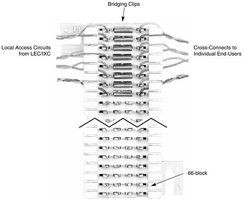
In this figure, columns 1 and 2 are connected, as are columns 3 and 4. These column pairs (1/2 and 3/4) are often prewired. Each of the four columns is connected to one of the four pins on a phone connector. Column 1 is the often used as the "incoming" column and column 4 is used as the "outgoing" column, with each row connected to a pin on a cable leading to an office drop.
Bridge clips are little metal clips used to wire "straight through," for example, to connect columns 2 and 3. If it is necessary to crosswire a circuit, you cannot use bridging clips to connect a wire from column 2 in one row to column 3 in a different row; in that case, the connection must be wired. This arrangement has made 66-blocks very popular in telephone and network cable management.
Figure 6-5 illustrates what a 66-block installation would look like at a customer premise.
Figure 6-5. Customer Premise 66-block
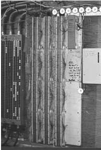
Figure 6-6 illustrates a complete dedicated circuit termination at the customer premise, with a 66-block used to extend the demarc from the NIU to the CSU/DSU.
Figure 6-6. End-to-End Access Circuit (with Extended Demarc)
EAN: 2147483647
Pages: 269