LAN Interconnection and Internetworking
The realm of LAN interconnection devices offers a number of options, including hubs, LAN switches, virtual LANs (VLANs), bridges, routers, and IP switches. These options are described in the following sections.
Hubs
Hubs interconnect the wiring that is connected to workstations. They are a building block of most networks, although these days, they have largely been replaced by LAN switches. There are three major types of hubs:
- Active Active hubs regenerate and retransmit signals, just as a repeater does. Because hubs typically have 8 to 12 ports for network computers to connect to, they are sometimes called multiport repeaters. Active hubs require electrical power to run (that's why they're called active).
- Passive Passive hubs serve as connection points and do not regenerate the signal; the signal simply passes through the hub. They do not require electrical power to run (that's why they're called passive). Wiring panels and punchdown blocks are examples of passive hubs.
- Hybrid Hybrid hubs accommodate several different types of cables.
You can connect hubs to expand a hub network. The advantages of hubs are that they make it easy to change or expand wiring systems, they use different ports to accommodate different cabling types, and they centralize the monitoring of network activity and traffic. Hubs are also sometimes called concentrators or multistation access units (MSAUs).
A group of transceivers can all be located in and managed by an intelligent hub. Intelligent hubs are modular and chassis based, with slots that accommodate the user's choice of interface modulessuch at Ethernet, Token Ring, or FDDIfor connectivity to LANs, WANs, or other network devices. The number of ports on the NIC determines the number of users in the particular star. Intelligent hubs often provide integrated management and internetworking capabilities, as well as Simple Network Management Protocol (SNMP)based network management. New generations also offer bridging, routing, and switching functions.
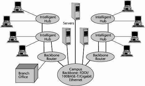
Figure 6.7 shows a network that uses a combination of interconnection devices. Intelligent hubs provide connectivity between workstations that comprise a given cluster. An internal backbone is used to internetwork the intelligent hubs to move between different clusters. Those intelligent hubs then connect into a backbone router for purposes of WAN, or campuswide, connectivity. (Note that today switches are preferred over hubs.)
Figure 6.7. Using interconnection devices
LAN Switches
LAN switches are a very cost-effective solution to the need for increased bandwidth in workgroups. Each port on the switch delivers a dedicated channel to the device or devices attached to that port, thereby increasing the workgroup's total bandwidth and also the bandwidth available to individual users.
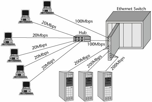
Figure 6.8 shows a simple example of a switched Ethernet configuration. One workstation requires 100Mbps on its own, so it has the full services of a 100Mbps port on the switched Ethernet card. Five workstations, on the other hand, each need 20Mbps, so one 100Mbps port serves all five workstations. These five workstations connect into a hub, and that hub connects into the actual port. (Today such configurations are largely managed by the local switches.) Servers have extra bandwidth requirementsthe ones in Figure 6.8 require 200Mbpsso they are each served by a bonding of several 100Mbps ports.
Figure 6.8. An example of a switched Ethernet configuration
The key applications for LAN switches are to interconnect the elements of a distributed computing system, to provide high-speed connections to campus backbones and servers, and to provide high bandwidth to individual users who need it. Instead of sharing a 10Mbps or 100Mbps LAN among a number of terminals in a workgroup, a LAN switch can be used, and an individual workstation can get the entire 10Mbps or 100Mbps. LAN switches provide great scalability because they enable the network to increase in bandwidth with the fairly simple addition of more switched ports. In addition, switches operate in full-duplex mode and as such use dedicated outgoing and incoming channels to allow full-speed transmission in both directions at the same time. Thus, LAN switches have many benefits, including scalability in terms of bandwidth, flexibility, and high performance.
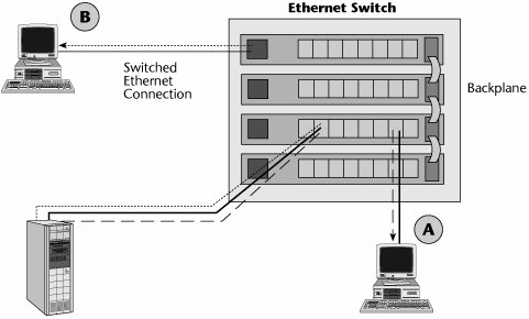
Figure 6.9 shows how an Ethernet switch can be used to connect devices that are on the same segment, some of which are served by one shelf of the Ethernet switch and others of which are served by connecting shelves. On the backplane, you can provide internetworking between the Ethernet segments, so you can provide internetworking on a campuswide basis.
Figure 6.9. An Ethernet switch
As the amount of traffic has grown in enterprises and as the nature of applications has become more sophisticated, we have been increasing the bandwidth associated with LANs. Today, it is common to see 10Mbps being delivered to an individual desktop and 100Mbps serving as the cluster capacity. To facilitate internetworking between these high-capacity desktops and Fast Ethernet clusters, Gigabit Ethernet is increasingly being used in the backbone. As shown in Figure 6.3 earlier in the chapter, Gigabit Ethernet switches can connect underlying 100Mbps or 10Mbps LAN segments, and the 10Mbps or 100Mbps LAN switches can deliver 10Mbps to the desktop and 100Mbps to the segment.
VLANs
Switched LANs enable us to create VLANs. A VLAN does not completely fit the earlier definition of a LAN as being limited in geographical scope; with a VLAN, geography has no meaning. A VLAN is a logically independent network, and multiple VLANs can coexist on an individual physical switch. VLANs are used extensively in campus networks, allowing users to be part of the same broadcast domain while being physically separated, on different floors of a building, or in different buildings on a campus. This is because a VLAN is defined by software rather than by hardware and physical location. The major difference is that VLANs can restrict the broadcast and collision domain to members of a particular VLAN. Figure 6.10 shows an example of a VLAN.
Figure 6.10. An example of a VLAN

A switched VLAN is a high-speed, low-latency broadcast group that unites an arbitrary collection of endstations on multiple LAN segments. Switched virtual networking eliminates the bottlenecks normally associated with a physical LAN topology by creating high-speed switched connections between endstations on different LAN segments. Users who want to belong to a particular broadcast domain do not have to be physically located on that LAN segment.
VLANs provide a software-based, value-added function by enabling the creation of a virtual broadcast domain, a shared LAN segment within a switched environment. Switching latencies on VLANs are typically one-tenth those of fast routers. However, routers are still required for inter-VLAN communications.
Bridges
Bridges, which entered the networking scene before routers, are used for connecting network segments (e.g., by creating the appearance of a single logical VLAN out of 5 to 10 individual clusters). A bridge can also be used to increase the number of computers on a network or to extend the distance of a segment beyond what the specifications allow. Similarly, a bridge can be used for network segmentation in order to reduce traffic bottlenecks or to control the flow of network traffic. Bridges can connect similar as well as dissimilar networks, which is their main application.
Bridges have several important functions:
- Learning When a bridge is first connected to the network, it sends an announcement that says, "Hello. I'm your new bridge. What's your address?" All the other devices respond with, "Hello. Welcome to the neighborhood," along with their addresses. The bridge builds a table of local addresses, called the Media Access Control (MAC) sublayer addresses. The MAC sublayer (which is equivalent to OSI Layer 2) controls access to the shared transmission medium. It is responsible for making the data frames and putting bits in fields that make sense, and it works with the physical layer (Layer 1 of the OSI model). MAC standards, including IEEE 802.3, 802.4, and 802.5, define unique frame formats. Every NIC has a globally unique burned-in MAC address.
- Performing packet transfer Bridges either filter, ignore, or forward packets.
- Using the Spanning Tree Protocol (STP) Bridges and switches use STP to provide a loop-free topology for any bridged LAN. Loops occur when there are alternate routes between hosts, creating multiple active paths between stations. Without STP, it is possible that two connections might be simultaneously live, which could result in an endless loop of traffic on the LAN. STP works by creating a tree that spans all the switches in an extended network and disables all alternate or redundant links that are not part of that tree. However, the disabled or blocked redundant links are available as a backup in case the initial link fails, supporting path redundancy. Bridge PDUs (BPDUs) are the frames that carry the STP information.
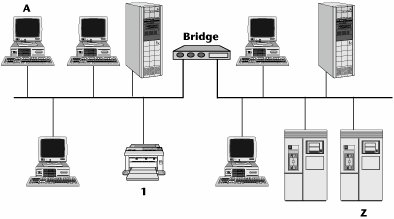
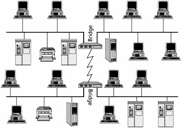
Figure 6.11 illustrates a local bridge installed between two LAN segments located at the same local premises. When the bridge is plugged in, it sends out a hello message to its community and learns addresses by snooping on other traffic, and then the bridge builds an addressing table. Say that PC A wants to send a document to printer 1. The bridge realizes that the printer resides within its community. It knows the address and it therefore does not do anything except filter the packet. On the other hand, if PC A is attempting to communicate with server Z, the bridge says, "I don't know where that server is. It's not part of my local community, so it must be somewhere else on the other side of this bridge." The bridge then broadcasts that information to the other side of the bridge. In essence, the bridge creates broadcast storms.
Figure 6.11. An example of a local bridge
Bridges are not networkable devices; that is, they can't target a destination network. They can only determine whether a destination is or is not on its segment, and if the destination is somewhere else, the bridge sends a message to every somewhere else that it knows about. This can be an especially big problem if you use a bridge in a remote mode, as shown in Figure 6.12, because, in essence, you are trying to connect remote locations by using a WAN link, which is expensive in terms of bandwidth. You pay for every bit sent, so sending messages to LAN segments that don't need to see them across a WAN link that doesn't need to be congested is inefficient.
Figure 6.12. An example of remote bridges
Although bridges can operate in local and remote areas, today they are mostly used in the local environment. They operate at OSI Layer 2, and they are point to pointthey do not understand networking or routing and relaying through a series of nodes. Bridges are protocol independent (Layer 3 and up), which keeps the software simple and inexpensive. Bridges cannot translate between different Layer 2 protocols (e.g., between Ethernet and Token Ring). They are primarily used to isolate traffic loads in the local environment because they offer fast throughput; because a bridge doesn't have to do intelligent routing, it is faster and less expensive than a traditional router. Over time, the best features of bridges and routers have been merged so that some of the problems with each have begun to disappear.
Routers
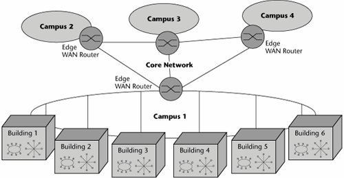
The most popular internetworking device today is the router (see Figure 6.13). The applications for routers are quite similar to those for bridges. You use them for network segmentation and connection; that is, you use them either to segment larger networks into smaller ones or to connect smaller networks into a larger virtual whole. You can use a router to switch and route packets across multiple communications paths and disparate Layer 2 network types, and because it is a Layer 3 device, a router is networkableit understands how to read network addresses and how to select the destination or target network, so it limits broadcast storms by not propagating them. This capability allows routers to act as firewalls between LAN segments. Routers can be associated with traffic filtering and isolation, and because they can read information about the network and transport protocols used, they can make forwarding decisions.
Figure 6.13. An example of routers in a network
Routers can make linking and rerouting decisions, which makes possible selective routing of individual packets over multiple communication paths. Remember that bridges have to disable all but one path, whereas a router can decide on-the-fly between numerous communications paths. The path a router selects depends on the user's requirements, including cost, speed, and priority.
Routers are protocol specific, but modern routers support multiple protocols, such as TCP/IP or IPX/SPX (the network and transport layer protocols used in Novell's NetWare network operating system). The key is that each of the protocols a router supports for internetworking requires its own separate routing table, so the more protocols the router supports, the more complex, memory intensive, and expensive it is due to the size and stability of the associated routing tables. Routers can be used as bridges to connect similar and dissimilar networks, and they are often applied as firewalls.
The functions of a router are as follows:
- Learning A router learns who its neighbors are and builds a forwarding table based on their addresses.
- Filtering A router forwards traffic by looking at its routing table for the next hop.
- Routing and switching A router selects the best destinations based on the network addresses, distance, cost, and availability.
- Adapting to network conditions A router adapts to network conditions by changing what it considers to be the best or optimum paths, depending on the network traffic status.
How do routers actually work? A router has input ports for receiving packets and output ports for sending those packets toward their destination. When the packet comes to the input port, the router examines the packet header and checks the destination against a routing table (i.e., a database that tells the router how to send packets to various destinations). Based on the information in the routing table, the router sends the packet to a particular output port, and the output port sends the packetspossibly to the destination, or possibly to another router that is one step closer to that packet's destination. Packets are delivered from node to node (i.e., router to router) because, at each node, the router modifies the MAC address to be that of the next node. The destination network address does not change, of course, but the destination MAC changes at each node; this is the only way the packet can travel from one node to the next.
If packets come to the input port more quickly than the router can process them, they are sent to a holding area called an input queue. The router then processes packets from the queue in the order in which they were received. If the number of packets received exceeds the length of the queue, packets may be lost due to the router running out of available memory. When this happens, an error control mechanism (such as TCP) that is housed on the sending and receiving computers has the packets resent. (You'll learn more about TCP in Chapter 8, "The Internet and IP Infrastructures.")
Types of Routing Tables
There are two types of routing tables:
- Static The simpler kind of routing table is the static routing table. In a static routing table, there are specific ways of routing data to other networks, and only those paths can be used. New routes can be added to the routing table, but they have to be manually programmed. Static routing can't adjust routes as network traffic changes, so it isn't an optimal option for many applications today. A static router knows only its own routing table and does not communicate changes to any of its neighbors.
- Dynamic Dynamic routing is much more useful than static routing. It allows a packet to take one of multiple routes to reach its final destination, and individual packets in a stream from one destination to another might follow different routes. Dynamic routing also allows routers to change the way they route information, based on the amount of network traffic on some paths and routers. In dynamic routing, the routing table changes as network conditions change. A dynamic router communicates with other routers so that they can all update their tables to reflect any changes.
Routing Protocols
There are two broad types of routing protocols: interior and exterior. Interior routing protocols are typically used only in the routers of an enterprise's intranet (i.e., its internal network). Interior routing protocols include Routing Information Protocol (RIP) and Open Shortest Path First (OSPF). Exterior protocols are typically used for routers located in the Internet, which is composed of many different providers. Another application for exterior protocols is where routers are connecting systems between different organizations. Whereas there may be many different interior routing schemes, a single exterior routing system manages the whole global Internet, called Border Gateway Protocol 4 (BGP4). (Routing protocols are discussed in detail in Chapter 8.)
Routers use a hierarchical addressing scheme, whereby the address includes both the network address and the node address. Routers operate at Layer 3, so they are networkableyou can route and relay traffic through a series of routers. Routers are protocol sensitive, so the more internetworking protocols they support, the more complex the software and the greater the number of routing tables and algorithms required to support those protocols.
IP Switches
The network core is responsible for providing interconnectivity, server access, and network management to the edge devices on the network periphery. At the edge of a LAN, a shortage of network capacity, coupled with proliferation of broadcasts and multicasts, can create significant network problems. When the edge demand exceeds the capacity of the core, buffer overruns create capacity overload and lead to lost packets, reducing the availability and reliability of the network. As a result, users today suffer from congestion, inadequate server access, and slow response times. (But to be truthful, this is often a symptom of poor design and planning rather than technological inferiority.) People want to see information in a matter of a few seconds, so these problems are increasingly frustrating.
The solution to the problem of these increases in traffic in the core and at the edge is the IP switch. The IP switch was designed to speed up choked networks. IP switches replace the slower, more processing-intensive routers. Routers, in general, are slower than switches because they must examine multiple packet fields, make substitutions in the packet headers, and then compute the routes on a packet-by-packet basis. All this activity introduces congestion and latency. The idea behind IP switching is to make what is essentially a connectionless data technology behave like the more reliable circuit-switched network. The goal is to make networksintranets, extranets, and the Internetfaster, as well as to enable the deployment of new genres of applications, including voice, video, and other streaming traffic.
IP switching has two major objectives. One is to add quality of service (QoS) support to IP. (QoS is discussed in detail in Chapter 8.) If we can make a network behave in a connection-oriented fashion, we can allocate resources end to end that promise to meet the required service level. (In the LAN domain, today's 1Gbps and 10Gbps Ethernet standards provide a great deal of bandwidth, so QoS is less of an issue. But when you get to the WAN edge, QoS becomes a greater concern.) The second objective of IP switching is to provide a way to scale economically because we know that data traffic is growing at a substantial rate (about 30% to 40% per year). IP switching basically replaces a network that consists entirely of Layer 3 hop-by-hop routing and the subsequent associated delays with a route-once/switch-everything-else scenario. That is, the first packet between any two nodes is routed, and then all the subsequent packets between the nodes are switched at Layer 2 to the destination over the selected virtual circuit. This is referred to as a cut-through technique. IP switches vastly improve the performance at LAN/WAN integration points. As more routing lookup functions are moved from software into the ASIC chips, Layer 3 switches can inspect each packet just like a router at high speed, without using proprietary cut-through methods.
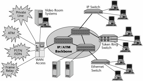
Figure 6.14 shows a switched LAN infrastructure that makes use of a high-speed packet backbone, which could be IP, ATM, or MPLS. An Ethernet switch serves a cluster, and a token-ring switch serves another cluster. An IP switch serves a high-demand cluster. The infrastructure also includes individual servers as well as WAN access devices, all connected to the WAN edge devices, which in this case are the IP switches that help connect or establish a connection-oriented link end to end and thereby guarantee latencies and improve the performance associated with the internetwork.
Figure 6.14. A switched LAN infrastructure with an IP/ATM backbone
Part I: Communications Fundamentals
Telecommunications Technology Fundamentals
- Telecommunications Technology Fundamentals
- Transmission Lines
- Types of Network Connections
- The Electromagnetic Spectrum and Bandwidth
- Analog and Digital Transmission
- Multiplexing
- Political and Regulatory Forces in Telecommunications
Traditional Transmission Media
Establishing Communications Channels
- Establishing Communications Channels
- Establishing Connections: Networking Modes and Switching Modes
- The PSTN Versus the Internet
The PSTN
- The PSTN
- The PSTN Infrastructure
- The Transport Network Infrastructure
- Signaling Systems
- Intelligent Networks
- SS7 and Next-Generation Networks
Part II: Data Networking and the Internet
Data Communications Basics
- Data Communications Basics
- The Evolution of Data Communications
- Data Flow
- The OSI Reference Model and the TCP/IP Reference Model
Local Area Networking
- Local Area Networking
- LAN Basics
- LAN Characteristics
- LAN Interconnection and Internetworking
Wide Area Networking
The Internet and IP Infrastructures
- The Internet and IP Infrastructures
- Internet Basics
- Internet Addressing and Address Resolution
- The Organization of the Internet
- IP QoS
- Whats Next on the Internet
Part III: The New Generation of Networks
IP Services
Next-Generation Networks
- Next-Generation Networks
- The Broadband Evolution
- Multimedia Networking Requirements
- The Broadband Infrastructure
- Next-Generation Networks and Convergence
- The Next-Generation Network Infrastructure
Optical Networking
- Optical Networking
- Optical Networking Today and Tomorrow
- End-to-End Optical Networking
- The Optical Edge
- The Optical Core: Overlay Versus Peer-to-Peer Networking Models
- The IP+Optical Control Plane
- The Migration to Optical Networking
Broadband Access Alternatives
- Broadband Access Alternatives
- Drivers of Broadband Access
- DSL Technology
- Cable TV Networks
- Fiber Solutions
- Wireless Broadband
- Broadband PLT
- HANs
Part IV: Wireless Communications
Wireless Communications Basics
- Wireless Communications Basics
- A Brief History of Wireless Telecommunications
- Wireless Communications Regulations Issues
- Wireless Impairments
- Antennas
- Wireless Bandwidth
- Wireless Signal Modulation
- Spectrum Utilization
Wireless WANs
- Wireless WANs
- 1G: Analog Transmission
- 2G: Digital Cellular Radio
- 5G: Enhanced Data Services
- 3G: Moving Toward Broadband Wireless
- Beyond 3G
- 4G: Wireless Broadband
- 5G: Intelligent Technologies
WMANs, WLANs, and WPANs
Emerging Wireless Applications
- Emerging Wireless Applications
- The Handset Revolution
- Mobile IP
- The IP Multimedia Subsystem
- Mobile Gaming
- Mobile Video
- Mobile TV
- Mobile Content
Glossary
EAN: 2147483647
Pages: 160
