Pens and Brushes
When you render images to a drawing surface, you need an object to actually do the drawing. GDI+ provides two objects: the Pen and the Brush. (Makes sense, don't you think?) The Pen type is used to draw the outline of a shape, and the Brush type fills in an enclosed shape.
Pens
You've all worked with a pen, so the idea of what a pen does shouldn't be hard to visualize. Normally, you use a pen to draw the outline of the object. Most likely, you draw a solid line, but sometimes you might use a sequence of a bunch of dots and dashes. When you're drawing a line between two objects, you probably will put an arrow on one or both ends. If you like variety, you might even use a red or blue pen along with your black one.
The Pen type provided by GDI+ provides basically the same functionality.
Custom Pens
You use the Pen constructor to create a Pen object, and then you use its properties (see Table 11-12) to indicate how you want the Pen used. There are several constructors to create a Pen, but in most cases the simple color and width constructors do the trick.
| PROPERTY | DESCRIPTION |
|---|---|
| Color | Specifies the color of the Pen |
| CompoundArray | Specifies the splitting of the width of a line into multiple parallel lines |
| CustomEndCap | Specifies a custom cap for the end of the line |
| CustomStartCap | Specifies a custom cap for the start of the line |
| DashCap | Specifies the dash-dot-space pattern used at the cap of a line |
| DashOffset | Specifies the distance from the start of the line to the beginning of the dash-dot-space pattern |
| DashPattern | Specifies a predefined dash-dot-space pattern to be used for a line |
| DashStyle | Specifies the style of the dash lines |
| EndCap | Specifies a predefined cap to be used for the end of the line |
| LineJoin | Specifies the style of the join between two consecutive lines |
| PenType | Specifies the style of the line generated by the Pen |
| StartCap | Specifies a predefined cap to be used for the start of the line |
| Width | Specifies the width of the Pen |
Pen pen1 = new Pen(Color::Blue, 3.0);
Or if you want the Pen to be only 1 graphics unit thick, you could use the even easier:
Pen pen2 = new Pen(Color::Blue);
Notice I used the term "graphics unit." The Pen type's thickness is based on the graphics unit, not pixels, though the default is pixels.
Named Pens
If you are creating a pen that is only 1 graphics unit thick and uses a named color, then you can use one of the pens found in the Pens class. The name of the pen is the same as the name of the named color it is using.
Pen *pen = Pens::AliceBlue;
System Pens
System pens are virtually the same as named pens, except that instead of a pen being named after a color, it is named after the role that the Pen would use on the Windows GUI interface. Also, you will find system pens in the SystemPens class and not in the Pens class.
Pen *pen = SystemPens::MenuText;
Listing 11-12 presents an example program that draws a few lines using the CompoundArray, DashStyle, StartCap, and EndCap properties.
Listing 11-12: Creating Some Random Lines
namespace DrawingLines { using namespace System; using namespace System::ComponentModel; using namespace System::Collections; using namespace System::Windows::Forms; using namespace System::Data; using namespace System::Drawing; using namespace System::Drawing::Drawing2D; public __gc class Forml : public System::Windows::Forms::Form { public: Form1(void) { pen = new Pen*[5]; // a one unit width black pen pen[0] = Pens::Black; // a one unit with purple pen broken with dashes pen[1] = new Pen(Color::Purple); pen[1]->DashStyle = DashStyle::Dash; // a 4 unit width chocolate pen pen[2] = new Pen(Color::Chocolate, 4); // A 8 width royalblue pen made up of three lines narrow wide narrow pen[3] = new Pen(Color::RoyalBlue, 10); Single cArray[] = { 0.0f, 0.1f, 0.3f, 0.7f, 0.9f, 1.0f }; pen[3]->CompoundArray = cArray; // a 5 width tomato pen with diamond start and round end anchors pen[4] = new Pen(Color::Tomato, 5); pen[4]->StartCap = LineCap::DiamondAnchor; pen[4]->EndCap = LineCap::RoundAnchor; InitializeComponent(); } protected: void Dispose(Boolean disposing) //... private: System::ComponentModel::Container * components; private: Pen *pen[]; void InitializeComponent(void) { this->BackColor = System::Drawing::Color::White; this->ClientSize = System::Drawing::Size(300, 300); this->Name = S"Form1"; this->Text = S"Drawing Some lines"; this->Paint += new System::Windows::Forms::PaintEventHandler(this,Forml_Paint); } private: System::Void Form1_Paint(System::Object * sender, System::Windows::Forms::PaintEventArgs * e) { Random *rand = new Random(); Graphics *g = e->Graphics; for (Int32 i = 0; i < 10; i++) { g->DrawLine(pen[i%5], rand->Next(0,299), rand->Next(0,299), rand->Next(0,299), rand->Next(0,299)); } } }; } Figure 11-12 shows one instance of DrawingLines.exe running. I doubt you will ever see the same combination of lines being displayed twice.
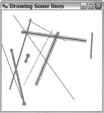
Figure 11-12: Displaying random lines
The preceding code is pretty self-explanatory, with the help of the embedded comments, except for two things. The first is that you need to add the System::Drawing::Drawing2D namespace. This namespace defines both the DashStyle and LineCap classes.
The second is the code that implements the CompoundArray property. This property splits a single line into multiple parallel lines. It does this by taking the width of a line and defining some portions as visible and other portions as not visible. The basic idea is, starting at 0 percent, find the first percent value that the line will be visible and write that into a Single area, and then find the percent where it becomes invisible again and write that value into the area. Repeat the process for all the parallel sublines that make up the full area, stopping at 100 percent.
If you want to define the entire line width as being visible (a waste of time, by the way), the array will look like this:
Single cArray[] = { 0.0f, 1.0f }; If you want to define the top half of the line as visible and the bottom as invisible (again, a waste of time), the array will look like this:
Single cArray[] = { 0.0f, 0.5f }; If you want the top 10 percent and the bottom 10 percent only to be visible, the array will look like this:
Single cArray[] = { 0.0f, 0.1f, 0.9f, 1.0f }; Notice that the compound array always has an even number of elements.
The preceding example breaks the line like this:
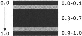
So the code ends up looking like this:
pen[3] = new Pen(Color::RoyalBlue, 10); Single cArray[] = { 0.0f, 0.1f, 0.3f, 0.7f, 0.9f, 1.0f }; pen[3]->CompoundArray = cArray;
Brushes
You use brushes to fill in the objects that you drew with the pens you defined in the previous section. Unlike the Pen class, the Brush class is an abstract class. You don't create objects directly from the Brush class; instead, brushes are created from classes derived from the Brush class such as SolidBrush, HatchBrush, and TextureBrush.
You can also create named brushes and SystemBrushes. The Brushes class will fill a shape like the SolidBrush class. The only difference is that the brushes are predefined with names based on named colors.
Brush *brush = Brushes::AliceBlue;
SystemBrushes are like the Brushes class, but instead of colors, the SystemBrushes are named based on the Windows role they would represent.
Brush *brush = SystemBrushes:: ActiveBorder;
SolidBrush, HatchBrush, and TextureBrush are not the only brushes available, but I cover only them to give you some ideas on how to work with brushes.
Solid Brushes
The SolidBrush class is the easiest of the brushes. All it takes in its constructor is the color that you want to fill the shape with. Its only property with any relevance is the color you used in the constructor.
SolidBrush *brush = new SolidBrush(Color::Black);
Hatch Brushes
The HatchBrush class is a little more complicated than the SolidBrush class. First, you need to add the namespace System::Drawing::Drawing2D so that you can access the both the HatchBrush class and the HatchStyle enumeration. The HatchBrush uses the HatchStyle enumeration (see Table 11-13) to define the look of the brush. GDI+ provides numerous hatch styles.
| ENUMERATION | DESCRIPTION |
|---|---|
| BackwardDiagonal | Specifies a pattern of diagonal lines from the upper right to lower left |
| Cross | Specifies a pattern of vertical and horizontal lines |
| DiagonalBrick | Specifies a pattern that looks like slanted bricks |
| Divots | Specifies a pattern that looks like divots (a golfer's nightmare) |
| Horizontal | Specifies a pattern of horizontal lines |
| Plaid | Specifies a pattern that looks like plaid |
| SmallConfetti | Specifies a pattern that looks like small confetti |
| Sphere | Specifies a pattern of spheres laid adjacent to each other |
| Vertical | Specifies a pattern of vertical lines |
| ZigZag | Specifies a pattern of horizontal lines that looks like zigzags |
The constructor is a little more complicated too, as you need to pass the HatchStyle and two colors, the first being the foreground hatch color and the second being the background color.
using namespace System::Drawing::Drawing2D; //... HatchBrush *b = new HatchBrush(HatchStyle::Divots, Color::Brown, Color::Green);
Textured Brushes
A TextureBrush class allows you to place an image in the brush and then use it to fill in shapes. The best part of TextureBrush is how little code is needed to get it to work. The basic tasks behind the creation of a TextureBrush are loading the image and then placing it in the brush:
Image *brushimage = new Bitmap(S"MyImage.bmp"); TextureBrush *tbrush = new TextureBrush(brushimage);
Because I haven't covered images yet, I defer their explanation until later in the chapter. But as you can see in the preceding constructor, once you have an image available, it is a simple process to place it into a TextureBrush.
But that is not where the story ends. What happens if the brush is smaller than the shape it is trying to fill? The TextureBrush provides a WrapMode parameter (see Table 11-14) in the constructor (and also a property) to determine what to do—either clamp it or tile it. Clamping means that only one copy of the image is drawn, and tiling means that the image is repeatedly drawn until the area is filled.
| ENUMERATION | DESCRIPTION |
|---|---|
| Clamp | Clamp the image to the object boundary |
| Tile | Tile the shape |
| TileFlipX | Tile the shape, flipping horizontally on each column |
| TileFlipXY | Tile the shape, flipping horizontally and vertically |
| TileFlipY | Tile the shape, flipping vertically on each row |
There is one more piece of the puzzle. The first brush starts in the upper-left corner of the control you are drawing in. Thus, if you are filling a rectangle, for instance, and you want the brush to start in the upper-left corner of the rectangle, then you need to call the Brush class's TranslateTransform() method to translate the brush to start at that location:
// Translate brush to same start location as rectangle tbrush->TranslateTransform(25,25); // Fill rectangle with brush g->FillRectangle(tbrush, 25, 25, 250, 250);
Listing 11-13 shows the tiling of the TextureBrush using WrapMode::TileFlipXY. It also shows how to translate the starting point of the tiling to the upper-left corner of the shape you are trying to fill.
Listing 11-13: Filling with a TextureBrush
namespace TextureBrush1 { using namespace System; using namespace System::ComponentModel; using namespace System::Collections; using namespace System::Windows::Forms; using namespace System::Data; using namespace System::Drawing; using namespace System::Drawing::Drawing2D; public __gc class Form1 : public System::Windows::Forms::Form { public: Forml(void) //... protected: void Dispose(Boolean disposing) //... private: System::ComponentModel::Container * components; void InitializeComponent(void) { this->AutoScaleBaseSize = System::Drawing::Size(6, 15); this->ClientSize = System::Drawing::Size(292, 265); this->Name = S"Form1"; this->Text = S"Texture Brush"; this->Paint += new System::Windows::Forms::PaintEventHandler(this,Form1_Paint); } private: System::Void Form1_Paint(System::Object * sender, System::Windows::Forms::PaintEventArgs * e) { Graphics *g = e->Graphics; // Load Image Image *bimage = new Bitmap(S"MCppCover.jpg"); // Create brush TextureBrush *tbsh = new TextureBrush(bimage, WrapMode::TileFlipXY); // Translate brush to same start location as rectangle tbsh->TranslateTransform(25,25); // Fill rectangle with brush g->FillRectangle(tbsh, 25, 25, 250, 250); } }; } Figure 11-13 shows TextureBrush.exe in action. Remember to make sure that the bitmap file is in the current executable starting directory so the program can find it. If it is not in the current executable starting directory, the program will abort.
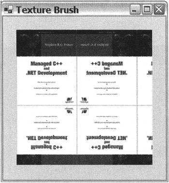
Figure 11-13: Displaying the tiled TextureBrush
EAN: 2147483647
Pages: 169