IP-to-IP Gateway Features
IPIPGW supports a rich set of features for providing the SBC functionality. As it supports both TDM and IP-to-IP calls, it also provides a smooth transition path for customers who currently have PSTN interconnects and are migrating to VoIP interconnects. Few of the features, which help in interconnecting voice and video networks, are described in more detail.
Video Support
Cisco Multiservice IPIPGW supports video calls for H.323 deployments. With the support for video, you can use the IPIPGW for extending the rich media experience between two enterprises by interconnecting their video networks while providing security, quality, reliability, and scalability. In addition to the benefits that the Cisco Multiservice IPIPGW feature offers in the voice network, it also provides the following features for video networks:
- H.261, H.263, and H.264 codec support.
- Far-end camera control (FECC) support, which enables an endpoint to control the remote camera on a video call that is connected through the IPIPGW.
- Support for T.120 data collaboration in flow-around mode.
- Resource Reservation Protocol (RSVP) synchronization and differentiated services code point (DSCP) marking for video streams. This feature provides enhanced QoS through RSVP synchronization with the H.323 signaling protocol and DSCP packet marking.
- New vendor-specific attribute (VSA) for improved accounting of bandwidth usage. You can configure Cisco gateways to use the max-bit-rate VSA to report bandwidth usage to accounting servers.
- Support for generic data capabilities for inline data content.
Codec transparent is a concept supported with the IPIPGW and is useful for video deployments. You can also use it in voice deployments. By configuring codec transparent on the incoming and the outgoing dial peers, IPIPGW transparently passes the codec from one leg to another. Only codecs that are supported by the IPIPGW are transparently passed. If an unsupported codec is requested, call setup will fail. The codec transparent command eases the configuration and leaves it up to the two endpoints to negotiate the codec for the call.
Address Hiding
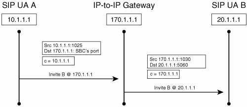
The architecture of the IPIPGW has been built such that it inherently performs the function of hiding IP addresses, as shown in Figure 18-4. The call signaling is terminated at the gateway and then reoriginated using the IP address of the Cisco IPIPGW. The media can also be terminated and reoriginated, thus providing complete privacy of the endpoint or network that is generating the call. It also creates a point of demarcation between the two networks, which eases manageability and troubleshooting.
Figure 18-4. Address Hiding for SIP Call Flow
When configuring the interfaces on the IPIPGW, you can use various combinations:
- Two Ethernet interfaces, with different IP addresses associated with them.
- A single Ethernet interface or a single loopback interface, if it is properly routed between the two networks. Both sides of the networks would be communicating with this one IP address and receiving signaling and media information from this one IP address.
- One Ethernet interface and one loopback interface.
You can bind only one protocol, H.323 or SIP, to the single loopback interface.
Security
With VoIP deployment on the rise, the need for providing security for voice calls is also increasing. IPIPGW supports a rich set of security mechanisms for both H.323 and SIP protocols.
H.323 Deployments
Security for VoIP calls is provided by using the following:
- IPsec tunnels for encrypting the H.323 signaling traffic
- Secure RTP (SRTP) for media encryption
One IPsec tunnel is created between the originating endpoint and the IPIPGW, and the second tunnel is created between the IPIPGW and the terminating endpoint. These static IPsec tunnels provide an end-to-end secure signaling channel for the H.323 messages. The keys, which are negotiated in the H.225 messages, are relayed by the IPIPGW from one leg to another. Media is also encrypted using SRTP, and it flows through the gateway without its payload being changed. Only the Layer 3 IP address of the SRTP packets is modified for providing the address-hiding feature.
SIP Deployments: Transport Layer Security
Another security feature that is supported on the IPIPGW is the Transport Layer Security (TLS) protocol. TLS is implemented over the TCP. TLS provides two security functionalities:
- Mutual authentication This is based on mutually exchanging certificates signed by a trusted certificate authority (CA) server.
- Signaling encryption During the handshake phase, the IPIPGW and the originating or terminating gateway negotiate a dynamically generated symmetric key and cipher algorithms through TLS. When the negotiation is successful, the SIP signaling is encrypted or decrypted using the exchanged symmetric key.
Digest Authentication
The Cisco IPIPGW supports HTTP digest authentication and provides a stateless challenge-response mechanism for authentication based on digest access. Figure 18-5 illustrates HTTP digest authentication. When the SIP proxy server receives a SIP request from the IPIPGW without credentials, it challenges the request with a 401 or 407 unauthorized. The IPIPGW then responds to the challenge and supplies the required credentials for the call to be successfully completed.
Figure 18-5. Message Exchange for Digest Authentication

Digest authentication is configured under the sip-ua configuration mode. The command syntax is authentication username username password password [realm realm]. Example 18-6 illustrates the configuration commands for implementing digest authentication.
|
[View full width] IPIPGateway#config t IPIPGateway(config)#sip-ua IPIPGateway(config-sip-ua)#authentication username userone password jackson realm cisco.com jackson realm cisco.com
|
DTMF Interworking
Because the IPIPGW terminates and reoriginates the signaling call leg, the DTMF relay tones need to be transmitted across the 2 call legs. Based on the configuration, you can send a similar DTMF type across the outbound VoIP type or, in certain cases, you can change the DTMF type from one type to another, as shown in Table 18-1.
|
DTMF Relay Type at Origination Side |
DTMF Relay Type at Termination Side |
|---|---|
|
H323 <-> H323 |
|
|
H245 alphanumeric |
H245 alphanumeric |
|
H245 signal |
H245 signal |
|
RFC 2833 |
RFC 2833 |
|
H245 alphanumeric |
H245 signal |
|
RFC 2833 |
H245 signal |
|
RFC 2833 |
H245 alphanumeric |
|
H323 <-> SIP |
|
|
H245 alphanumeric |
NOTIFY |
|
H245 alphanumeric |
RFC 2833 |
|
H245 signal |
NOTIFY |
|
H245 signal |
RFC 2833 |
|
RFC 2833 |
NOTIFY |
|
RFC 2833 |
RFC 2833 |
|
SIP <-> SIP |
|
|
NOTIFY |
NOTIFY |
|
RFC 2833 |
RFC 2833 |
For example, you can transmit H.245 alphanumeric as the same H.245 alphanumeric DTMF, or you can convert the H.245 alphanumeric on the H.323 call leg to SIP RFC 2833, or SIP NOTIFY on the SIP call leg, and vice versa. For DTMF types such as RFC 2833, the media must flow through the IPIPGW.
Admission Confirm (ACF)/Location Confirm (LCF) DTMF Relay is configured under the VoIP dial peer configuration mode. It needs to be configured under both the incoming as well as the outgoing VoIP dial peer. The command syntax is dtmf-relay cisco-rtp|h245-alphanumeric|h245-signal|rtp-nte|sip-notify. Example 18-7 illustrates the configuration commands for implementing RFC 2833 dtmf type.
IP-to-IP_GW(config)#dial-peer voice 1 voip IP-to-IP_GW(config-dial-peer)#dtmf-relay rtp-nte |
Fax Support
A fax call is treated similarly to a voice call. Standards-based T.38 and other fax types such as Cisco fax relay and fax pass-through are supported. Interworking between H.323 and SIP fax calls is also supported. When you configure fax, you can use the regular fax commands either globally or under the specific inbound and outbound VoIP dial peers. Interworking between various fax types is not possible. For example, you cannot convert a T.38 fax call to a fax pass-through call.
Quality of Service
The Cisco Multiservice IPIPGW supports all the QoS features that are available in Cisco IOS. Features such as low-latency queuing (LLQ), IP precedence, and DSCP are supported on the gateway. You could remark the signaling, in addition to media packets, appropriately before sending the traffic into the network. By applying the right QoS policies, you can provide better service to selected traffic. You can use the regular Cisco IOS commands for QoS for configuration.
Call Admission Control
CAC is a deterministic and informed decision made before you establish a voice or video call. CAC is based on whether the required network resources are available to provide suitable QoS for the new call. Different CAC mechanisms are supported on the Cisco Multiservice IPIPGW and, based on the need and network design of the specific customers, you could apply one of the following mechanisms.
RSVP-Based CAC
Cisco IPIPGW uses RSVP to limit the accepted voice or video load on the IP network to guarantee the QoS levels of calls. The Cisco IPIPGW CAC that is using RSVP synchronizes RSVP signaling with the protocol (H.323 or SIP) signaling to ensure that the bandwidth reservation is established in both directions before a call moves to the alerting phase (ringing). This ensures that the called party phone rings only after you have reserved the resources for the call. With RSVP-based admission control, the IPIPGW can reserve network bandwidth and react appropriately if bandwidth reservation fails.
Max Connections-Based CAC
The maximum connections CAC mechanism involves using the max-conn VoIP dial-peer configuration command on a dial peer of the outgoing leg to restrict the number of concurrent connections (calls) that can be active on that dial peer at any one time.
IP Call Capacity-Based CAC
CAC can also be provided based on carrier ID. Carrier ID is an attribute that consists of up to 127 alphanumeric characters that identify the carrier that is handling H.323 calls. This CAC mechanism works in conjunction with a Cisco gatekeeper. You can match incoming calls that have a certain carrier ID configured. Only the configured maximum capacity of calls is allowed to traverse the IPIPGW.
You configure the IP circuit under the voice service voip and h323 configuration mode. The command syntax is ip circuit carrier-id carrier name reserved-calls reserved. The carrier name defines an IP circuit using the specified name as the circuit ID, and the reserved keyword defines the maximum number of calls for the circuit ID. Example 18-8 illustrates the configuration commands for ip circuit. max-calls sets the number of maximum aggregate H.323 IP circuit carrier call legs. The reserved-calls number has to be double the number of calls allowed to pass the IPIPGW. Therefore, in Example 18-8, 200 calls would be allowed through the gateway for carrier XYZ. Also, more than one carrier ID can be configured.
IPIPGateway#config t IPIPGateway(config)#voice service voip IP-to-IP_GW(conf-voi-serv)#h323 IP-to-IP_GW(conf-serv-h323)#ip circuit max-calls 800 IP-to-IP_GW(conf-serv-h323)#ip circuit carrier-id XYZ reserved-calls 400 |
Thresholds Based on CPU, Memory, and Total Calls
It is critical to configure the gateway so that it accepts calls based on certain resources. If the resources are being highly used or are falling below configured limits, you should reject the incoming calls with a configured type of treatment. You can configure call treatment to send a certain type of a cause code so that the originating gateway can reroute the call to the next available gateway. You can provision CAC based on monitoring certain resources of the IPIPGW, such as these:
- CPU
- Memory
- Total number of calls
You can configure the IPIPGW to handle VoIP based on the minimum and maximum limits that are configured. Based on the resource that is monitored, you could apply appropriate treatment when the resource reaches the configured low or high threshold window mark.
You configure CAC based on CPU, memory, and total calls in the global configuration mode.
The command syntax for configuring call threshold based on CPU utilization for the last 5 seconds is call threshold global cpu-5sec low low-threshold high high-threshold. Example 18-9 illustrates the configuration commands for setting a CPU low threshold of 5 percent and a high threshold of 90 percent measured in the last 5 seconds.
IPIPGateway(config)#call threshold global cpu-5sec low 5 high 90 |
The command syntax for configuring call threshold based on average CPU utilization is call threshold global cpu-avg low low-threshold high high-threshold. Example 18-10 illustrates the configuration commands for configuring thresholds of the average CPU utilization for 5 percent (low) or 75 percent (high).
IPIPGateway(config)#call threshold global cpu-avg low 5 high 75 |
The command syntax for configuring call threshold based on average CPU utilization is call threshold global total-mem low low-threshold high high-threshold. Example 18-11 illustrates the configuration commands for enabling CAC based on memory. The low threshold is set to 10 percent, and the high threshold is set to 75 percent of the gateway memory.
IPIPGateway(config)#call threshold global total-mem low 10 high 75 |
The command syntax for configuring call threshold based on total number of calls that the IPIPGW would handle is call threshold global total-calls low low-threshold high high-threshold. Example 18-12 illustrates the configuration commands for enabling CAC based on the total number of calls to be handled. The low threshold is set to 1 call, and the high threshold is set to 800 calls.
IPIPGateway(config)#call threshold global total-calls low 1 high 800 |
You need to turn on call treatment to take the appropriate action when the gateway resources hit the low or the high threshold mark. You can also configure call treatment so that a particular cause code is returned. The command syntax for enabling call treatment is call threshold on. Example 18-13 illustrates the configuration commands for enabling call treatment. Various options of what cause code could be sent are shown in the call treatment cause-code command.
IPIPGatewayconfig)#call treatment on IPIPGateway(config)#call treatment cause-code ? busy Insert cause code indicating the GW is busy (17) no-QoS Insert cause code indicating the GW can't provide QOS (49) no-resource Insert cause code indicating the GW has no resource (47) |
Transcoding
Transcoding functionality is supported on the IPIPGW routers. Using transcoding services reduces bandwidth on the WAN side, resulting in tangible cost savings. DSP farms provide the transcoding services using DSP resources that are installed either on the router motherboard or on high-density digital voice/fax network modules. The transcoding functionality is supported between G.711 and G.729 codecs. Table 18-2 lists the variants and packetizations.
|
Codec |
Packetization Periods for Transcoding (ms) |
|---|---|
|
G.711 a-law, G.711 μ-law |
10, 20, or 30 |
|
G.729, G.729A, G.729B, G.729AB |
10, 20, 30, 40, 50, or 60 |
Note
Only 2800s, 2600XMs, 2691, 3700s, and 3800s support transcoding.
You can use the DSP farm that is used for the transcoding on the same router platform as the IPIPGW or on an external router.
IPIPGW uses the Skinny server to talk to the DSP farm. When you enable transcoding on the IPIPGW, you use the same configuration commands that you used in the Cisco CallManager Express (CME).
VXML and Tcl Scripts
You can run voice XML and Toolkit Command Language (Tcl) scripts on the IPIPGW. DSPs are not required for use of this feature. You have to record prompts in the same codec type that you use for the call. For example, you should use prompts that are recorded in G711μlaw for G711μlaw calls. The scripts are applied to the VoIP dial peer. Because of the rich set of DTMF types that are supported (for example, H.245 alphanumeric, H.245 signal, SIP RFC 2833, and SIP NOTIFY), this is a useful feature for many customers who are deploying services, such as prepaid calling cards.
Billing
You can collect call detail records (CDRs) on the IPIPGW, similar to the way you collect them on a regular Cisco IOS TDM gateway. The CDRs are generated for both legs of the call, regardless of whether it is an H.323 or a SIP call. Conference ID is the common field, which you can use to corelate the two call legs for the voice call. Capability for gathering voice quality statistics based on packet loss, jitter, and round trip time is available.
show Commands
You can use many of the show commands that are employed on the Cisco voice gateways on the IPIPGW. Each voice call that passes through the IPIPGW has two VoIP media streams in the media flow-through. Example 18-14 illustrates the show command for checking the two VoIP media streams on the IPIPGW in the media flow-through mode. The command output displays the active RTP connections and the call identifiers for each leg of the VoIP. Connection 1, which is call identifier 31, signifies the connection between the IPIPGW and the originating endpoint. Connection 2 (Call ID 32) signifies the second call leg, which is the connection between the IPIPGW and the terminating endpoint. The User Datagram Protocol (UDP) ports are shown for the local (IPIPGW) and remote endpoints (originating and terminating endpoints). The LocalIP is the IP address of the IPIPGW, and the RemoteIP is the IP address of the originating and terminating endpoint.
|
[View full width] IP-to-IP_GW#show voip rtp connections VoIP RTP active connections : No. CallId dstCallId LocalRTP RmtRTP LocalIP RemoteIP 1 31 32 17612 17978 200.1.1.3 60.60.60.75 2 32 31 18164 29128 200.1.1.3 200.1.1.75 Found 2 active RTP connections
|
debug Commands
The following debug commands are helpful for troubleshooting IPIPGW call flows. Based on the protocols that you are using, you can turn on the appropriate debugs to diagnose the problem.
- H.323H.323 scenarios:
- debug h225 asn1
- debug h225 events
- debug h245 asn1
- debug h245 events
- debug h225 q931
- debug cch323 all
- debug gatekeeper main 10
- debug voip ipipgw
- debug voip ccapi inout
- H.323SIP scenarios:
- debug h225 asn1
- debug h225 events
- debug h245 asn1
- debug h245 events
- debug cch323 all
- debug voip ipipgw
- debug voip ccapi inout
- debug ccsip all
- SIP-SIP scenarios:
- debug ccsip all
- debug voip ccapi inout
- RSVP scenarios:
- debug call rsvp-sync events
- debug call rsvp-sync func-trace
Case Study Providing Enterprise VoIP Trunking to VoIP Service of the Service Provider |
Part I: Voice Gateways and Gatekeepers
Gateways and Gatekeepers
- Gateways and Gatekeepers
- The Role of Voice Gateways
- The Role of Voice Gatekeepers
- The Role of IP-to-IP Gateways
- Introduction to Voice Protocols
- Call Control Agents
- Deployment Scenarios
- Case Study: Introduction
- Chapter Review Questions
Part II: Gateways
Media Gateway Control Protocol
- Media Gateway Control Protocol
- Introduction to MGCP
- MGCP Operation
- Call Flow with MGCP
- Dial Plan Considerations
- Implementing MGCP Gateways
- Securing MGCP Gateways
- Troubleshooting Tools
- Case Study: Configuring an MGCP Gateway
- Review Questions
H.323
- H.323
- H.323 Specifications
- H.323 Network Components
- Call Flow
- H.323 Protocol Pros and Cons
- When to Use H.323
- Dial Plan Considerations
- Implementing H.323 Gateways
- Securing H.323 Gateways
- Troubleshooting Tools
- Case Study: Configuring an H.323 Gateway
- Review Questions
Session Initiation Protocol
- Session Initiation Protocol
- Description of SIP
- SIP Call Flow
- SIP Pros and Cons
- When to Use SIP
- Dial Plan Considerations
- Implementing SIP Gateways
- Securing SIP Gateways
- Allowing H.323 to SIP Connections
- Troubleshooting Tools
- Case Study: Configuring SIP Between a Gateway and CallManager 5.x
- Review Questions
Circuit Options
Connecting to the PSTN
- Connecting to the PSTN
- PSTN Circuit Selection Overview
- Analog Trunks
- Digital Trunks
- Case Study: Add an E1 R2 Connection to the Leeds Gateway
- Review Questions
Connecting to PBXs
- Connecting to PBXs
- Analog Trunks
- Digital Trunks
- Configuring Transparent Common Channel Signaling
- Case Study: Implementing a Cisco Voice Gateway at the Shanghai Office
- Review Questions
Connecting to an IP WAN
- Connecting to an IP WAN
- Applications for Connecting to an IP WAN
- Design Considerations
- Quality of Service
- Providing Fax and Modem Services
- Security
- Case Study: Using a T1 Link as a Tie Line
- Review Questions
Dial Plans
- Dial Plans
- Numbering Plans
- Overlapping Numbering Plans
- Building a Scalable Dial Plan
- Dial Peers
- Dial Peer Matching
- Case Study: Configuring PSTN Access
- Review Questions
Digit Manipulation
- Digit Manipulation
- Basic Digit Manipulation
- Number Expansion
- Voice Translation Rules and Profiles
- Manipulating Caller ID
- Order of Operation in Digit Manipulation
- Troubleshooting Digit Manipulation
- Case Study
- Review Questions
Influencing Path Selection
- Influencing Path Selection
- Hunt Groups
- Using Trunk Groups
- Tail-End Hop-Off
- Call Admission Control
- POTS-to-POTS Call Routing Considerations
- Case Study: Implementing Gateway-Controlled RSVP
- Review Questions
Configuring Class of Restrictions
- Configuring Class of Restrictions
- COR Overview
- COR Operation
- Implementing COR
- Assigning COR Lists with SRST
- Assigning COR Lists with Cisco CallManager Express
- Restricting Inbound Calls
- Case Study: Implementing COR for Miami
- Review Questions
SRST and MGCP Gateway Fallback
- SRST and MGCP Gateway Fallback
- SRST Overview
- Configuring SRST
- Dial Plan Considerations
- SRST Features
- SIP SRST
- Call Preservation
- Secure SRST
- MGCP Gateway Fallback
- Configuring MGCP Gateway Fallback
- Verifying and Troubleshooting SRST
- Verifying and Troubleshooting MGCP Gateway Fallback
- Case Study: Integrating SRST with an Analog Voice-Mail System
- Review Questions
DSP Resources
- DSP Resources
- Need for DSP Resources
- Determining the DSP Resources Required
- Configuring DSP Resources
- Transcoding for CallManager Express
- Case Study: Add DSP Resources to the Miami Gateway
- Review Questions
Using Tcl Scripts and VoiceXML
- Using Tcl Scripts and VoiceXML
- Tcl IVR and VoiceXML Application Overview
- Sample Applications
- Downloading Tcl Scripts from Cisco.com
- Configuring the Gateway to Use a Tcl Script
- Implementing the AA Tcl Script
- Creating Audio Files
- Restrictions and Caveats
- Case Study: Implementing ACD Application
- Review Questions
Part III: Gatekeepers
Deploying Gatekeepers
- Deploying Gatekeepers
- Gatekeeper Functionality
- Gatekeeper Signaling
- E.164 Number Resolution
- Call Admission Control
- Gatekeeper Deployment Models
- Gatekeepers with CallManager
- Security with Gatekeepers
- Review Questions
Gatekeeper Configuration
- Gatekeeper Configuration
- Configuring Basic Gatekeeper Functionality
- Multiple Gatekeeper Configurations
- Configuring Directory Gatekeepers
- Troubleshooting Gatekeepers
- CallManager and Gatekeepers
- Gatekeeper Redundancy
- Configuring Resource Availability Indicator
- Configuring Gatekeeper Security
- Case Study: Deploying Gatekeepers to Assist in Migration to VoIP
- Review Questions
Part IV: IP-to-IP Gateways
Cisco Multiservice IP-to-IP Gateway
- Cisco Multiservice IP-to-IP Gateway
- IP-to-IP Gateway Overview
- Cisco Multiservice IP-to-IP Gateway
- Basic Configuration
- IP-to-IP Gateway Features
- Case Study: Providing Enterprise VoIP Trunking to VoIP Service of the Service Provider
- Review Questions
Appendix A. Answers to Chapter-Ending Review Questions
Index
EAN: 2147483647
Pages: 218
