Configuring Transparent Common Channel Signaling
When multiple PBXs exist in a private network, they are often connected using leased-line circuits from the PSTN as tie trunks between the PBXs. Many vendors have implemented proprietary protocols to carry features such as number display, name display, and networked voice mail across these tie trunks. This method makes the multiple PBXs appear to end users as a single, virtual PBX with a common dial plan and common features across all locations.
A disadvantage of this design is that dedicated pointto-point circuits are required between the PBX locations. If several locations exist, it might be necessary to implement a mesh design for the tie trunks. This can be a costly design, because there is a monthly recurring cost to each of these circuits. Further, you cannot use these circuits for any other purpose, even when call volume is low. Standard PRI or CAS circuit implementations on voice gateways do not work because of the proprietary protocols in use.
T-CCS allows the connection of two PBXs that use a proprietary or unsupported common channel signaling (CCS) protocol without the need for interpretation of CCS for call processing. The signaling is passed through transparently to the other side.
Using a T-CCS implementation, the PBX voice channels are nailed up (made permanent) and compressed between sites. You can transmit the accompanying signaling channel or channels transparently across the data network between the locations. Thus, the voice gateway does not route the calls from the PBXs on a call-by-call basis; instead, it follows a preconfigured, permanent route to the destination.
You can implement T-CCS in two primary ways:
- Frame forwarding mode You can only use frame forwarding T-CCS to support PBX proprietary protocols where the signaling channel or channels are HDLC-framed and the desired VoX technology is Voice over Frame Relay (VoFR) or Voice over ATM (VoATM). In this solution, the high-level data link control (HDLC) signaling frames are encapsulated and forwarded through a channel group that is configured for the signaling on the controller. The HDLC framing is interpreted and understood, although the signaling messages are not looked at or acted upon. Idle frames are suppressed, and only real data is propagated across the signaling channel.
- Clear-channel mode Clear-channel T-CCS is used to support PBX proprietary protocols in which the signaling channel(s) are ABCD-bit based or HDLC, or where the voice transport technology is Voice over IP (VoIP). In this solution, the signaling channel and voice channels are configured as DS0 groups, and all are treated as voice calls.
The voice-bearer channels are permanent trunk connections and can be compressed if desired using the voice coder/decoder (codec) of your choice. The signaling channel is also permanently connected using the clear-channel codec. The clear-channel codec passes the signaling transparently to the other side.
Use of frame forwarding mode has declined in recent years as networks have moved to an IP infrastructure and VoIP has gained popularity. When T-CCS is implemented today, it is almost always done using clear-channel mode. With clear-channel T-CCS, there is no intelligence in the software to know which channels are voice channels and which are signaling channels. You must configure the timeslots that you know carry signaling traffic to match a dial peer that assigns the clear-channel codec. The voice channels must match a dial peer that can encode voice using a compression codec scheme, such as G.729.
Figure 7-6 shows the flow of the traffic between Site A and Site B. Note that the signaling channel passes through transparently, whereas the voice channels are compressed before being sent over the network. This optimizes the use of the data network bandwidth while keeping the signaling intact.
Figure 7-6. T-CCS Clear Channel Signaling Flow
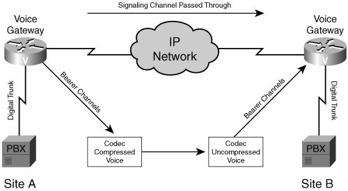
The channels on the proprietary digital trunk from the PBX at Site A are disassembled in the voice gateway. The signaling channel is passed through transparently. The voice gateway does not see or act on any of the signaling information on the channel. The voice-bearer channels are sent individually on permanent connections between the voice gateways. You can compress voice channels by using a compression algorithm, such as G.729. At Site B, you can reassemble the channels and pass them across the digital trunk in their original form to the PBX.
To configure T-CCS, you need to begin by creating a DS0 group for each channel on the controller that you want to transport. Each DS0 group contains a single timeslot. The type is defined as external signaling using the ext-sig parameter of the ds0-group command, as shown in Example 7-18.
Miami#show running-config ! ! Unnecessary output deleted ! controller T1 1/0 framing esf clock source line primary linecode b8zs ds0-group 0 timeslots 1 type ext-sig ds0-group 1 timeslots 2 type ext-sig ds0-group 2 timeslots 3 type ext-sig ds0-group 3 timeslots 4 type ext-sig . . . ds0-group 23 timeslots 24 type ext-sig ! voice-port 1/0:0 timeouts call-disconnect 3 ! voice-port 1/0:1 timeouts call-disconnect 3 ! voice-port 1/0:2 timeouts call-disconnect 3 ! voice-port 1/0:3 timeouts call-disconnect 3 . . . voice-port 1/0:23 timeouts call-disconnect 3 ! end |
Each DS0 group that is defined creates an associated voice port. After the voice ports are created, you must set them up as trunk connections using the connection trunk word command. In this case, word is the telephone number of the corresponding trunk on the far end of the connection. You can assign these numbers arbitrarily as long as they do not conflict with any other number used in the system. When you are configuring the trunk connections, configure one side to answer the call. You can do this by using the connection trunk word answer-mode command. Only use the answer-mode subcommand on one side of the trunk connection.
After you have configured the trunk information, you need to add a POTS dial peer for each voice port. The number on the destination pattern must match the telephone number of the trunk on the far end of the connection and is defined using the destination-pattern number command. The port must be the local voice port that connects to the far-end trunk.
You also need to set up VoIP dial peers to make the connection to the remote side. Be sure you create a separate dial peer for the bearer and signaling channels. The bearer channels can use whatever codec is appropriate, but G.729 is the default. The signaling channel must use the clear channel codec to function properly. You configure this by using the codec clear-channel command.
A complete sample configuration for Site A and Site B is shown in Example 7-19.
SiteA#show running-config ! ! Unnecessary output deleted ! network-clock-participate slot 1 network-clock-select 1 T1 1/0 ! interface Loopback0 ip address 10.10.10.1 ! controller T1 1/0 framing esf clock source line primary linecode b8zs ds0-group 0 timeslots 1 type ext-sig ds0-group 1 timeslots 2 type ext-sig ds0-group 2 timeslots 3 type ext-sig . . . ds0-group 23 timeslots 24 type ext-sig ! voice-port 1/0:0 timeouts call-disconnect 3 connection trunk 6000 ! voice-port 1/0:1 timeouts call-disconnect 3 connection trunk 6001 ! voice-port 1/0:2 timeouts call-disconnect 3 connection trunk 6002 . . . voice-port 1/0:23 timeouts call-disconnect 3 connection trunk 4000 ! ! dial-peer voice 5000 pots destination-pattern 5000 port 1/0:0 ! dial-peer voice 5001 pots destination-pattern 5001 port 1/0:1 ! dial-peer voice 5002 pots destination-pattern 5002 port 1/0:2 ! dial-peer voice 3000 pots destination-pattern 3000 port 1/0:23 ! dial-peer voice 6000 voip destination-pattern 6... session target ipv4: 10.20.20.1 codec g729r8 ! dial-peer voice 4000 voip destination-pattern 4000 session target ipv4: 10.20.20.1 codec clear-channel ! end |
SiteB#show running-config ! ! Unnecessary output deleted ! network-clock-participate slot 2 network-clock-select 1 T1 2/0 ! interface Loopback0 ip address 10.20.20.1 ! controller T1 2/0 framing esf clock source line primary linecode b8zs ds0-group 0 timeslots 1 type ext-sig ds0-group 1 timeslots 2 type ext-sig ds0-group 2 timeslots 3 type ext-sig . . . ds0-group 23 timeslots 24 type ext-sig ! voice-port 2/0:0 timeouts call-disconnect 3 connection trunk 5000 ! voice-port 2/0:1 timeouts call-disconnect 3 connection trunk 5001 ! voice-port 2/0:2 timeouts call-disconnect 3 connection trunk 5002 . . . voice-port 2/0:23 timeouts call-disconnect 3 connection trunk 3000 ! ! dial-peer voice 6000 pots destination-pattern 6000 port 2/0:0 ! dial-peer voice 6001 pots destination-pattern 6001 port 2/0:1 ! dial-peer voice 6002 pots destination-pattern 6002 port 2/0:2 ! dial-peer voice 4000 pots destination-pattern 4000 port 2/0:23 ! dial-peer voice 5000 voip destination-pattern 5... session target ipv4: 10.10.10.1 codec g729r8 ! dial-peer voice 3000 voip destination-pattern 3000 session target ipv4: 10.10.10.1 codec clear-channel ! end |
When the configuration is complete on both ends, the trunks should become active. These trunks are permanently connected between the two voice gateways.
You can use the show voice port summary command to verify that the trunks are connected correctly, as shown in Example 7-20.
SiteA#show voice port summary IN OUT PORT CH SIG-TYPE ADMIN OPER STATUS STATUS EC ========= == ============ ===== ==== ======== ======== == 1/0:0 01 ext up up trunked trunked y 1/0:1 02 ext up up trunked trunked y 1/0:2 03 ext up up trunked trunked y . . . 1/0:23 24 ext up up trunked trunked y |
You can also use the show voice call summary command. This command shows you the codec in use for each connected trunk, as demonstrated in Example 7-21. Note that in this example, timeslot 24 is the signaling channel and is using the clear channel codec.
SiteA#show voice call summary PORT CODEC VAD VTSP STATE VPM STATE ============== ======== === ==================== ====================== 1/0:0.1 g729r8 y S_CONNECT S_TRUNKED 1/0:1.2 g729r8 y S_CONNECT S_TRUNKED 1/0:2.3 g729r8 y S_CONNECT S_TRUNKED . . . 1/0:23.24 clear-ch y S_CONNECT S_TRUNKED |
Part I: Voice Gateways and Gatekeepers
Gateways and Gatekeepers
- Gateways and Gatekeepers
- The Role of Voice Gateways
- The Role of Voice Gatekeepers
- The Role of IP-to-IP Gateways
- Introduction to Voice Protocols
- Call Control Agents
- Deployment Scenarios
- Case Study: Introduction
- Chapter Review Questions
Part II: Gateways
Media Gateway Control Protocol
- Media Gateway Control Protocol
- Introduction to MGCP
- MGCP Operation
- Call Flow with MGCP
- Dial Plan Considerations
- Implementing MGCP Gateways
- Securing MGCP Gateways
- Troubleshooting Tools
- Case Study: Configuring an MGCP Gateway
- Review Questions
H.323
- H.323
- H.323 Specifications
- H.323 Network Components
- Call Flow
- H.323 Protocol Pros and Cons
- When to Use H.323
- Dial Plan Considerations
- Implementing H.323 Gateways
- Securing H.323 Gateways
- Troubleshooting Tools
- Case Study: Configuring an H.323 Gateway
- Review Questions
Session Initiation Protocol
- Session Initiation Protocol
- Description of SIP
- SIP Call Flow
- SIP Pros and Cons
- When to Use SIP
- Dial Plan Considerations
- Implementing SIP Gateways
- Securing SIP Gateways
- Allowing H.323 to SIP Connections
- Troubleshooting Tools
- Case Study: Configuring SIP Between a Gateway and CallManager 5.x
- Review Questions
Circuit Options
Connecting to the PSTN
- Connecting to the PSTN
- PSTN Circuit Selection Overview
- Analog Trunks
- Digital Trunks
- Case Study: Add an E1 R2 Connection to the Leeds Gateway
- Review Questions
Connecting to PBXs
- Connecting to PBXs
- Analog Trunks
- Digital Trunks
- Configuring Transparent Common Channel Signaling
- Case Study: Implementing a Cisco Voice Gateway at the Shanghai Office
- Review Questions
Connecting to an IP WAN
- Connecting to an IP WAN
- Applications for Connecting to an IP WAN
- Design Considerations
- Quality of Service
- Providing Fax and Modem Services
- Security
- Case Study: Using a T1 Link as a Tie Line
- Review Questions
Dial Plans
- Dial Plans
- Numbering Plans
- Overlapping Numbering Plans
- Building a Scalable Dial Plan
- Dial Peers
- Dial Peer Matching
- Case Study: Configuring PSTN Access
- Review Questions
Digit Manipulation
- Digit Manipulation
- Basic Digit Manipulation
- Number Expansion
- Voice Translation Rules and Profiles
- Manipulating Caller ID
- Order of Operation in Digit Manipulation
- Troubleshooting Digit Manipulation
- Case Study
- Review Questions
Influencing Path Selection
- Influencing Path Selection
- Hunt Groups
- Using Trunk Groups
- Tail-End Hop-Off
- Call Admission Control
- POTS-to-POTS Call Routing Considerations
- Case Study: Implementing Gateway-Controlled RSVP
- Review Questions
Configuring Class of Restrictions
- Configuring Class of Restrictions
- COR Overview
- COR Operation
- Implementing COR
- Assigning COR Lists with SRST
- Assigning COR Lists with Cisco CallManager Express
- Restricting Inbound Calls
- Case Study: Implementing COR for Miami
- Review Questions
SRST and MGCP Gateway Fallback
- SRST and MGCP Gateway Fallback
- SRST Overview
- Configuring SRST
- Dial Plan Considerations
- SRST Features
- SIP SRST
- Call Preservation
- Secure SRST
- MGCP Gateway Fallback
- Configuring MGCP Gateway Fallback
- Verifying and Troubleshooting SRST
- Verifying and Troubleshooting MGCP Gateway Fallback
- Case Study: Integrating SRST with an Analog Voice-Mail System
- Review Questions
DSP Resources
- DSP Resources
- Need for DSP Resources
- Determining the DSP Resources Required
- Configuring DSP Resources
- Transcoding for CallManager Express
- Case Study: Add DSP Resources to the Miami Gateway
- Review Questions
Using Tcl Scripts and VoiceXML
- Using Tcl Scripts and VoiceXML
- Tcl IVR and VoiceXML Application Overview
- Sample Applications
- Downloading Tcl Scripts from Cisco.com
- Configuring the Gateway to Use a Tcl Script
- Implementing the AA Tcl Script
- Creating Audio Files
- Restrictions and Caveats
- Case Study: Implementing ACD Application
- Review Questions
Part III: Gatekeepers
Deploying Gatekeepers
- Deploying Gatekeepers
- Gatekeeper Functionality
- Gatekeeper Signaling
- E.164 Number Resolution
- Call Admission Control
- Gatekeeper Deployment Models
- Gatekeepers with CallManager
- Security with Gatekeepers
- Review Questions
Gatekeeper Configuration
- Gatekeeper Configuration
- Configuring Basic Gatekeeper Functionality
- Multiple Gatekeeper Configurations
- Configuring Directory Gatekeepers
- Troubleshooting Gatekeepers
- CallManager and Gatekeepers
- Gatekeeper Redundancy
- Configuring Resource Availability Indicator
- Configuring Gatekeeper Security
- Case Study: Deploying Gatekeepers to Assist in Migration to VoIP
- Review Questions
Part IV: IP-to-IP Gateways
Cisco Multiservice IP-to-IP Gateway
- Cisco Multiservice IP-to-IP Gateway
- IP-to-IP Gateway Overview
- Cisco Multiservice IP-to-IP Gateway
- Basic Configuration
- IP-to-IP Gateway Features
- Case Study: Providing Enterprise VoIP Trunking to VoIP Service of the Service Provider
- Review Questions
Appendix A. Answers to Chapter-Ending Review Questions
Index
EAN: 2147483647
Pages: 218
