Analog Circuits
Cisco voice gateways support three types of analog circuits:
- Foreign Exchange Station (FXS)
- Foreign Exchange Office (FXO)
- Ear and Mouth (E&M)
FXS/FXO
An FXO is a port type that connects subscribers to central office (CO) equipment or PBXs. You can use FXS to connect to regular analog phones or PBXs.
In general, an FXS port is a port that comes from the service offering equipment, whether it is a CO class five switch, a PBX, or a voice gateway. An FXO port is a port from an end device, such as a telephone, fax, or modem, that is connected to an FXS port to obtain telephony services.
FXS
FXS ports are the ports that you plug a telephone, fax, or modem into that provide telephony service. For example, an analog telephone that is connecting over twisted copper pairs to the port in a home or a port on a PBX is connecting to the FXS port of the telephone carrier or the private telephone exchange. FXS ports provide dial tone, battery current, and ring voltage to the subscriber device.
Dial tone is the current that the FXS port places on the analog circuit to inform the subscriber device that the line is ready to collect dual tone multifrequency (DTMF) tones for call routing.
Idle voltages range from 24V to 48V and are configurable. Ring voltage is the voltage that is placed on the analog circuit to inform subscriber devices of an incoming call.
Cisco routers provide 40Vrms 5 ring equivalence number (REN), which is sufficient to support on-premise equipment.
FXO
FXO ports are the ports on subscriber devices that connect to the CO or PBX to receive subscriber services. Examples are the port on a telephone, modem, or fax that connects to the FXS port in the wall, PBX, or voice gateway. PBX systems and voice gateways can also contain FXO ports that are connected to the CO. For example, you can connect an analog telephone FXO port to the FXS port from a PBX for voice service. This FXS port allows the analog phone to call other phones that are connected to the PBX. The PBX might also contain an FXO port that is connected to a CO FXS port. This FXO port allows the PBX to route calls from its FXS ports to the public switched telephone network (PSTN). On-hook/ off-hook indication is delivered to the FXS port by a change in voltage on the analog line.
FXO Power Failover
If the power to the router fails, a metallic path is established between certain FXO and FXS ports. You can mark the analog phones that are connected to these FXS ports as emergency phones for calling out to the PSTN even when the router is down.
FXS/FXO Supervisory Signaling
A subscriber device that is connected to an FXS port initiates communications by delivering off-hook indication. An FXS port detects the off-hook state and prepares to gather DTMF tones used to determine how to route the call. The remote FXS port applies ring voltage to the remote subscriber FXO, and the remote FXO detects ring voltage and goes off-hook, indicating reception of the call and closing of the call circuit. The call is ended by each local segment entering the on-hook state and the FXS port sending on-hook indication. You can accomplish supervisory signaling between FXS and FXO ports in two ways: loop-start and ground-start signaling.
Loop-Start Signaling
Loop-start signaling involves the breaking and connecting of the 48V circuit loop originating from the CO equipment. During the on-hook state, the subscriber equipment has a break on the loop, so no voltage is passing. When the subscriber equipment goes offhook, it closes the loop, and current flows. At this point, the CO detects the closing of the loop and provides a dial tone. To seize the far-end subscriber, the CO provides an analog current across the line called ring voltage. This current causes the subscriber device to "ring," indicating an incoming call. When the subscriber answers the call, or goes off-hook, the 48V circuit loop is closed and the CO turns off the ringing voltage. The call is now connected.
The loop-start method has the advantage of not requiring a common ground between the CO and subscriber equipment. However, it does not provide far-end disconnect monitoring. There is no mechanism in place to determine when the remote party has returned to the onhook state. There is also poor glare resolution with loop-start signaling. Glare occurs when both the CO and subscriber equipment attempt to seize the line at the same time.
Ground-Start Signaling
Ground-start signaling calls for the 48V circuit loop to be grounded on both sides of the connection. In the idle state, the subscriber has a break in the ring, and the CO has a break in the tip. When the subscriber seizes the line, it grounds the ring, allowing current to flow along the path. When the CO senses the ring ground, it grounds the tip. Upon detection of the tip ground, the subscriber closes the loop and removes the ring ground. This action connects the circuit. When the CO seizes the line, it grounds the tip, causing the subscriber to detect the current, close the loop, and remove the ring ground. Ground-start signaling provides far-end disconnect information because the CO can ground the tip when the remote subscriber has entered the on-hook state. It also minimizes instances of glare. However, it requires that both CO and subscriber equipment have a common ground.
Address Signaling
The FXO port sends address signaling to the FXS port to indicate the final destination of the call. Analog address signaling can use either pulsed digits or DTMF tones. DTMF is a common implementation of MF tones that defines eight reference frequencies and tone-pair to digit mapping.
Pulsed tones are rarely used today. Pulse tones were originally sent by spinning a dial wheel on a telephone. As this mechanical device spun, it opened and closed the circuit. The pulses, or duration of open and closed, vary by country but must be consistent within a specified tolerance.
Today, most analog circuits use DTMF tones to indicate the destination address. As you push the buttons on a touch-tone phone, two different frequencies are sent on the circuit. This combination of frequencies notifies the receiving side of the digits. Table 5-1 lists the frequencies that are associated with each button on a telephone keypad.
|
1209 |
1336 |
1477 |
1633 |
|
|---|---|---|---|---|
|
697 |
1 |
2 |
3 |
A |
|
770 |
4 |
5 |
6 |
B |
|
852 |
7 |
8 |
9 |
C |
|
941 |
* |
0 |
# |
D |
FXS-DID
Because address signaling is transmitted only from the FXO port to the FXS port, calls from the PSTN on a typical analog circuit do not indicate the end destination of a call. For a typical residential application, this is not an issue, because all phones on the associated line will ring. When the analog service is connected to a gateway or PBX, it would be beneficial to receive addressing signaling to allow calls to be routed to individual phones on the system. Some service providers offer this service by providing an FXO port as the demarcation. You can then connect an FXS port that is configured for direct inward dial (DID) service and receive address signaling from the PSTN. You cannot configure all FXS ports to support DID service.
Note
You cannot use FXS ports that are configured for DID service to place outbound calls.
Informational Signaling
The FXS port provides informational signaling using call progress tones. Call progress (CP) tones are audible tones that the FXS device sends to indicate the status of calls. Functions are determined by the frequency of tone sent and the cadence of the tone. For example, in the United States, a dial tone is a continuous generation of 350 Hz and 440 Hz, whereas a busy signal is 480 Hz and 620 Hz with a .5 second on/.5 second off cadence. A sample list of call progress tones is as follows:
- Busy signal
- Call waiting
- Dial tone
- Ring tone
- Congestion tone
- Audible ringback tone
CP Tones are country specific. Cisco voice gateways default to U.S. CP tones. You can select country-specific tones using the voice port command cptone, as shown in Example 5-1.
Gateway#config t Gateway(config)#voice-port 2/0/0 Gateway(config-voiceport)#cptone ? locale 2 letter ISO-3166 country code AR Argentina IS Iceland PE Peru AU Australia IN India PH Philippines AT Austria ID Indonesia PL Poland BE Belgium IE Ireland PT Portugal BR Brazil IL Israel RU Russian Federation CA Canada IT Italy SA Saudi Arabia CN China JP Japan SG Singapore CO Colombia JO Jordan SK Slovakia C1 Custom1 KE Kenya SI Slovenia C2 Custom2 KR Korea Republic ZA South Africa CY Cyprus LB Lebanon ES Spain CZ Czech Republic LU Luxembourg SE Sweden DK Denmark MY Malaysia CH Switzerland EG Egypt MX Mexico TW Taiwan FI Finland NP Nepal TH Thailand FR France NL Netherlands TR Turkey DE Germany NZ New Zealand GB United Kingdom GH Ghana NG Nigeria US United States GR Greece NO Norway VE Venezuela HK Hong Kong PK Pakistan ZW Zimbabwe HU Hungary PA Panama |
Caller ID
Caller ID is a service provider feature that allows the receiving party to be notified of the directory number of the calling party. Caller ID is based on Telcordia Publications TR-TSY-000030 and TR-TSY-000031 and is officially known as Calling Number Delivery (CND).
CND sends the calling party information between the first and second ring of a call. The information is sent as ASCII-encoded text in a 1200 bps stream of data bytes and includes the date, time, and calling party number and name.
FXO ports support inbound Caller ID. You can also configure a name and number for FXS ports by using the station-id command. This information is used for calls within a system only. Calls to the PSTN present the official directory information stored in the service provider database.
Note
CallManager-controlled Media Gateway Control Protocol (MGCP) gateways do not support inbound caller ID on FXO ports.
Supervisory Disconnect
Traditionally, there was no need for the FXS port to inform the FXO port of disconnect because the end user was a person. During a phone conversation, people indicate the end of the discussion or assume the end of a discussion by a prolonged silence. Even if the end user is a modem or fax, disconnect indication is not required because this type of device can detect when it loses the carrier from the far end. However, complications arise when the FXO port is part of another switching system, such as a PBX or voice gateway. During loop-start signaling, the status, or battery state, of the FXS device never changes. If the FXO port is on another switching device, the remote end might become disconnected, but the PBX or Voice over IP (VoIP) gateway has no indication of the disconnect. In this case, the FXO port can be left in a hung state.
The FXS port can signal call disconnect to the FXO port using several methods:
- If you use ground-start signaling, the FXO receives a disconnect indication when the voltage level changes.
- If you use loop-start signaling, you can configure the FXS port to temporarily deny power when the call disconnects. The FXO port can sense this short loss of power and disconnect the call. Power denial support is enabled by default on Cisco FXO ports.
- You can configure the FXS for battery reversal using the battery-reversal command under voice port configuration. FXS ports normally reverse battery polarity at the point of far-end answer. You can set the FXS to reverse the polarity again during farend hang-up to indicate disconnect to the FXO.
- The FXS can send a tone-based supervisory disconnect to the FXO. After receiving this tone, the FXO port knows that the call has disconnected. The tone that is sent varies by country. Example 5-2 shows how to configure Supervisory Tone Disconnect on an FXO port.
Gateway#config t Gateway(config)#voice-port 2/0/0 Gateway(config-voiceport)#supervisory disconnect dualtone mid-call Gateway(config-voiceport)#cptone us Gateway(config-voiceport)#timeouts wait-release 5 Gateway(config-voiceport)#timeouts call-disconnect 5 Gateway(config-voiceport)#exit |
If the default disconnect tone for a country does not work, you can specifically define the tone. You can modify settings for frequencies, power, delay, and cadence. You must obtain from the service provider the information that is required to configure the tone, or you must determine it using a frequency analyzer. Example 5-3 shows how to customize the disconnect tone.
|
[View full width] Gateway #configure terminal Gateway(config)#voice-port 3/1/1 Gateway(config-voiceport)#supervisory disconnect dualtone pre-connect voice-class 10 Gateway(config-voiceport)#end Gateway(config)#voice class dualtone 10 Gateway(config-voice-class)#freq-pair 1 350 440 Gateway(config-voice-class)#freq-max-deviation 5 Gateway(config-voice-class)#freq-max-power 6 Gateway(config-voice-class)#freq-min-power 25 Gateway(config-voice-class)#freq-power-twist 15 Gateway(config-voice-class)#freq-max-delay 16 Gateway(config-voice-class)#cadence-min-on-time 100 Gateway(config-voice-class)#cadence-max-off-time 250 Gateway(config-voice-class)#cadence-list 1 100 100 300 300 100 200 200 200 Gateway(config-voice-class)#cadence-variation 8 Gateway(config-voice-class)#exit voice-class 10 Gateway(config-voiceport)#end Gateway(config)#voice class dualtone 10 Gateway(config-voice-class)#freq-pair 1 350 440 Gateway(config-voice-class)#freq-max-deviation 5 Gateway(config-voice-class)#freq-max-power 6 Gateway(config-voice-class)#freq-min-power 25 Gateway(config-voice-class)#freq-power-twist 15 Gateway(config-voice-class)#freq-max-delay 16 Gateway(config-voice-class)#cadence-min-on-time 100 Gateway(config-voice-class)#cadence-max-off-time 250 Gateway(config-voice-class)#cadence-list 1 100 100 300 300 100 200 200 200 Gateway(config-voice-class)#cadence-variation 8 Gateway(config-voice-class)#exit
|
CAMA
Centralized Automated Message Accounting (CAMA) is an old telephony protocol that was developed for long-distance billing but is widely used today in the United States for enhanced 911 (E911) services. The protocol allows for both the calling and called number to be carried using in-band signaling. This is needed in 911 calling because 911 calls are routed to the appropriate service center based on the calling number. CAMA allows the telephone company to transmit the calling number to the public safety answering point (PSAP) dispatcher prior to establishing the audio connection. This is crucial information because it tells the dispatcher the exact location that the call is coming from and provides callback information if the call is disconnected.
Most E911 networks are standalone entities within their own region. Many states have laws requiring that businesses connect directly to the local E911 network, and this legislation is expected to be passed throughout the United States in the near term. More than 80 percent of the E911 networks in the United States consist of CAMA trunks, whereas some E911 regions allow alternative connections, such as ISDN. A CAMA trunk can either be an analog telephone line carrying MF signaling or a voice T1 with MF signaling. The enterprise device, whether it is a voice gateway or PBX, connects directly to the E911 device. This device routes the call to the appropriate PSAP based on the calling number of the incoming call.
You can configure VIC2 FXO ports to support CAMA signaling.
E&M
E&M signaling was developed to interconnect PBXs using dedicated circuits from the PSTN. Unlike the 2-wire FXS/FXO circuits, E&M circuits are 8-wire. The voice path uses either 2-wire or 4-wire. The remaining four wires are used for signaling. Table 5-2 lists the wires, or leads, that are used in E&M circuits.
|
Lead |
Description |
Pin |
|---|---|---|
|
SB |
-48V signaling battery |
1 |
|
M |
Signaling input |
2 |
|
R |
Ring, audio input |
3 |
|
R1 |
Ring, audio input/output |
4 |
|
T1 |
Tip, audio input/output |
5 |
|
T |
Tip, audio input |
6 |
|
E |
Signaling output |
7 |
|
SG |
Signaling ground |
8 |
E&M comes in six common variants: E&M Types I through V and E&M SSDC5. This section discusses E&M Types I through V. The Type indicates how the various signaling leads are used to indicate an off-hook or trunk seizure condition.
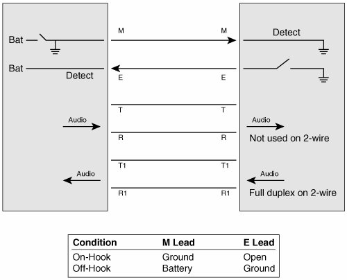
Type I Signaling
Type I signaling is the most common version seen in North America. Battery is provided on both the E and the M lead. During on-hook, both of the leads are open. The trunk circuit side indicates off-hook by connecting the M lead to the battery, while the signaling unit indicates off-hook by grounding the E lead, as shown in Figure 5-1.
Figure 5-1. E&M Type I Signaling
Type II Signaling
Type II signaling interfaces cause little interference and are typically used for sensitive environments. These interfaces use four leads for signaling: E, M, SB, and SG. During onhook, both the E and M lead are open. The trunk side indicates off-hook by connecting the M lead to the SB lead connected to the battery of the signaling side. The signaling side indicates off-hook by connecting the E lead to the SG lead that is connected to the trunk circuit ground.
Type III Signaling
Type III signaling is not commonly used. It also uses four leads, but during on-hook, the E lead is open and the M lead is set to the ground that is connected to the SG lead of the signaling side. The trunk side indicates off-hook by moving the M lead connection from the SG lead to the SB lead of the signaling side. The signaling unit indicates off-hook by grounding the E lead.
Type IV Signaling
Type IV signaling is similar to Type II. It also uses four leads, and during on-hook, both the E and the M leads are open. The trunk side indicates off-hook by connecting the M lead to the SB lead that is connected to the ground of the signaling side. The signaling side indicates off-hook by connecting the E lead to the SG lead that is connected to the ground of the trunk side.
Note
Cisco E&M voice interface cards (VIC) do not support E&M Type IV signaling.
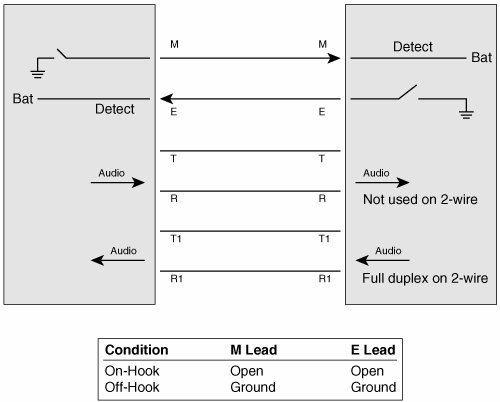
Type V Signaling
Type V signaling is the most common mechanism used outside of North America. It is similar to Type I, and it only uses the E and M leads. During on-hook, both leads are open. The trunk side indicates off-hook by grounding the M lead, while the signaling side indicates off-hook by grounding the E lead, as shown in Figure 5-2.
Figure 5-2. E&M Type V Signaling
Address Signaling
E&M supports three mechanisms of start dial signaling used between off-hook and digit collection: wink-start, delay-start, and immediate-start. Like FXS/FXO, both pulse dialing and DTMF can be used for address transmission.
Wink-Start
In wink-start operation, the originating device goes off-hook using the signaling leads as determined by the Type configuration. When the remote switch detects that the originating switch is off-hook, it transmits an off-hook pulse of approximately 140 to 290 ms in duration and then returns to the on-hook state. This is the "wink." The originating switch detects the wink, waits for at least 100 ms, and then outputs digits to the remote switch. The remote switch extends the call based on the receive digits. After the called party answers the call, the remote switch indicates call answer by transmitting off-hook.
Delay-Start
During delay-start, the originating switch waits a configurable time before inspecting the incoming signal from the remote switch. If the signal indicates on-hook, the originating switch outputs digits to the remote switch. If the signal is off-hook, the originating office waits until the signal returns to on-hook before forwarding digits. The remote switch indicates call answer by transmitting off-hook.
Immediate-Start
Immediate-start is the most basic of the trunk-signaling methods. The originating switch goes off-hook, waits for at least 150 ms, and then forwards digits.
Part I: Voice Gateways and Gatekeepers
Gateways and Gatekeepers
- Gateways and Gatekeepers
- The Role of Voice Gateways
- The Role of Voice Gatekeepers
- The Role of IP-to-IP Gateways
- Introduction to Voice Protocols
- Call Control Agents
- Deployment Scenarios
- Case Study: Introduction
- Chapter Review Questions
Part II: Gateways
Media Gateway Control Protocol
- Media Gateway Control Protocol
- Introduction to MGCP
- MGCP Operation
- Call Flow with MGCP
- Dial Plan Considerations
- Implementing MGCP Gateways
- Securing MGCP Gateways
- Troubleshooting Tools
- Case Study: Configuring an MGCP Gateway
- Review Questions
H.323
- H.323
- H.323 Specifications
- H.323 Network Components
- Call Flow
- H.323 Protocol Pros and Cons
- When to Use H.323
- Dial Plan Considerations
- Implementing H.323 Gateways
- Securing H.323 Gateways
- Troubleshooting Tools
- Case Study: Configuring an H.323 Gateway
- Review Questions
Session Initiation Protocol
- Session Initiation Protocol
- Description of SIP
- SIP Call Flow
- SIP Pros and Cons
- When to Use SIP
- Dial Plan Considerations
- Implementing SIP Gateways
- Securing SIP Gateways
- Allowing H.323 to SIP Connections
- Troubleshooting Tools
- Case Study: Configuring SIP Between a Gateway and CallManager 5.x
- Review Questions
Circuit Options
Connecting to the PSTN
- Connecting to the PSTN
- PSTN Circuit Selection Overview
- Analog Trunks
- Digital Trunks
- Case Study: Add an E1 R2 Connection to the Leeds Gateway
- Review Questions
Connecting to PBXs
- Connecting to PBXs
- Analog Trunks
- Digital Trunks
- Configuring Transparent Common Channel Signaling
- Case Study: Implementing a Cisco Voice Gateway at the Shanghai Office
- Review Questions
Connecting to an IP WAN
- Connecting to an IP WAN
- Applications for Connecting to an IP WAN
- Design Considerations
- Quality of Service
- Providing Fax and Modem Services
- Security
- Case Study: Using a T1 Link as a Tie Line
- Review Questions
Dial Plans
- Dial Plans
- Numbering Plans
- Overlapping Numbering Plans
- Building a Scalable Dial Plan
- Dial Peers
- Dial Peer Matching
- Case Study: Configuring PSTN Access
- Review Questions
Digit Manipulation
- Digit Manipulation
- Basic Digit Manipulation
- Number Expansion
- Voice Translation Rules and Profiles
- Manipulating Caller ID
- Order of Operation in Digit Manipulation
- Troubleshooting Digit Manipulation
- Case Study
- Review Questions
Influencing Path Selection
- Influencing Path Selection
- Hunt Groups
- Using Trunk Groups
- Tail-End Hop-Off
- Call Admission Control
- POTS-to-POTS Call Routing Considerations
- Case Study: Implementing Gateway-Controlled RSVP
- Review Questions
Configuring Class of Restrictions
- Configuring Class of Restrictions
- COR Overview
- COR Operation
- Implementing COR
- Assigning COR Lists with SRST
- Assigning COR Lists with Cisco CallManager Express
- Restricting Inbound Calls
- Case Study: Implementing COR for Miami
- Review Questions
SRST and MGCP Gateway Fallback
- SRST and MGCP Gateway Fallback
- SRST Overview
- Configuring SRST
- Dial Plan Considerations
- SRST Features
- SIP SRST
- Call Preservation
- Secure SRST
- MGCP Gateway Fallback
- Configuring MGCP Gateway Fallback
- Verifying and Troubleshooting SRST
- Verifying and Troubleshooting MGCP Gateway Fallback
- Case Study: Integrating SRST with an Analog Voice-Mail System
- Review Questions
DSP Resources
- DSP Resources
- Need for DSP Resources
- Determining the DSP Resources Required
- Configuring DSP Resources
- Transcoding for CallManager Express
- Case Study: Add DSP Resources to the Miami Gateway
- Review Questions
Using Tcl Scripts and VoiceXML
- Using Tcl Scripts and VoiceXML
- Tcl IVR and VoiceXML Application Overview
- Sample Applications
- Downloading Tcl Scripts from Cisco.com
- Configuring the Gateway to Use a Tcl Script
- Implementing the AA Tcl Script
- Creating Audio Files
- Restrictions and Caveats
- Case Study: Implementing ACD Application
- Review Questions
Part III: Gatekeepers
Deploying Gatekeepers
- Deploying Gatekeepers
- Gatekeeper Functionality
- Gatekeeper Signaling
- E.164 Number Resolution
- Call Admission Control
- Gatekeeper Deployment Models
- Gatekeepers with CallManager
- Security with Gatekeepers
- Review Questions
Gatekeeper Configuration
- Gatekeeper Configuration
- Configuring Basic Gatekeeper Functionality
- Multiple Gatekeeper Configurations
- Configuring Directory Gatekeepers
- Troubleshooting Gatekeepers
- CallManager and Gatekeepers
- Gatekeeper Redundancy
- Configuring Resource Availability Indicator
- Configuring Gatekeeper Security
- Case Study: Deploying Gatekeepers to Assist in Migration to VoIP
- Review Questions
Part IV: IP-to-IP Gateways
Cisco Multiservice IP-to-IP Gateway
- Cisco Multiservice IP-to-IP Gateway
- IP-to-IP Gateway Overview
- Cisco Multiservice IP-to-IP Gateway
- Basic Configuration
- IP-to-IP Gateway Features
- Case Study: Providing Enterprise VoIP Trunking to VoIP Service of the Service Provider
- Review Questions
Appendix A. Answers to Chapter-Ending Review Questions
Index
EAN: 2147483647
Pages: 218
