Quality of Service
Typically, data and voice traffic travel across the same WAN link. This can be a problem, because data tends to be transmitted in bursts and could use up all the bandwidth, leaving none for voice. QoS techniques help protect voice (and video) from data.
Planning is the most important part of QoS. In most networks, it is not enough to classify traffic as "voice" and "nonvoice" and give preference to voice. Most networks have various types of traffic, each with its own network needs and importance to the company. Although this book concentrates on voice, an effective QoS policy examines all the network applications and involves policy makers in deciding how to handle that data through the network. Your goal should be a consistent, end-to-end QoS strategy throughout your company.
One of your first tasks is to determine the needs of each network application. Voice is sensitive to delay, jitter, and drops. High-quality voice and interactive video have the following recommendations:
- A maximum of 150 ms of one-way delay
- A maximum of 30 ms of jitter
- A maximum of 1 percent packet loss
One cause of delay is small voice packets having to wait behind larger data packets to be sent out an interface. Jitter, which is variable delay, can result when some voice packets are sent out quickly and some have to wait. Drops happen when an interface queue is completely fullsomething much more likely to occur if voice has to share a queue with data. Thus, when you are sending voice and data across a WAN it is especially important to plan and implement QoS measures to increase the chances of voice always having the bandwidth it needs.
QoS involves three tasks:
- Classifying traffic
- Marking the classified traffic
- Configuring network devices to treat traffic differently based on the markings
The modular quality of service command-line interface (MQC) is the recommended method of implementing QoS. It involves using class maps to classify traffic, using policy maps to mark traffic or specify how it will be treated, and applying the policy using the service-policy command. In the following sections, you will look at using MQC with voice gateways.
Note
A full explanation of QoS is beyond the scope of this book. You can find detailed information in the Cisco QoS Solution Reference Network Design document at http://www.cisco.com/go/srnd, or in these books:
- Cisco Catalyst QOS: Quality of Service in Campus Networks by Michael Flannagan, Richard Froom, and Kevin Turek
- End-to-End QoS Network Design: Quality of Service in LANs, WANs, and VPNs by Christina Hattinghand and Tim Szigeti
Using Class Maps to Classify Traffic
Classifying traffic requires looking at it and identifying it according to some characteristic, such as port number or source address. After you classify traffic, you can configure routers and switches to treat it differently from other traffic. The MQC uses class maps to classify traffic. Classification can be based on many different things, but voice is typically identified by looking in the OSI Layer 4, Layer 3, or Layer 2 packet headers.
Classifying at Layer 4
You can classify traffic based on the port number in the TCP or User Datagram Protocol (UDP) packet header. Each voice application uses specific port numbers. Table 8-1 lists the default port numbers that common voice-related protocols use.
|
Protocol |
Port(s) Used |
|---|---|
|
SCCP[1] |
TCP ports 20002002 |
|
MGCP[2] |
UDP 2427 and 2727; TCP 2428 |
|
H.323 |
UDP 1718 and 1719; TCP 1720 and 1721 |
|
RTP[3] |
UDP ports 16,38432,767 |
|
SIP[4] |
TCP and UDP port 5060 (Cisco implementation) |
[1] SCCP = Skinny Client Control Protocol
[2] MGCP = Media Gateway Control Protocol
[3] RTP = Real-Time Transport Protocol
[4] SIP = Session Initiation Protocol
You can use either an access list or a class map to identify this traffic based on the port number. Example 8-1 shows how to do this with an access list. The access list is created and then referenced in a class map. This example classifies the SCCP signaling traffic separately from the voice RTP traffic.
VGateway#conf t VGateway(config)#ip access-list extended RTP VGateway(config-ext-nacl)#permit udp any any range 16383 32767 ! VGateway(config-ext-nacl)#ip access-list extended SCCP VGateway(config-ext-nacl)#permit tcp any any range 2000 2002 VGateway(config-ext-nacl)#exit ! VGateway(config)#class-map match-all VOICE VGateway(configs-cmap)#match access-group name RTP ! VGateway(configs-cmap)#class-map match-all SIGNALING VGateway(configs-cmap)#match access-group name SCCP |
This configuration gives you two class maps that break out two types of traffic, as verified in Example 8-2. The class map VOICE identifies the RTP traffic that is permitted in access list RTP, and the class map SIGNALING identifies the SCCP traffic that is permitted in access list SCCP. What about the rest of the data traveling around the network? A default class exists, and anything that is not explicitly identified falls into that, as shown in Example 8-2.
VGateway#show class-map Class Map match-any class-default (id 0) Match any Class Map match-all VOICE (id 2) Match access-group name RTP Class Map match-all SIGNALING (id 3) Match access-group name SCCP |
Example 8-3 shows a class map that matches RTP traffic directly. Using a class map in this way lets you bypass configuring an access list for RTP. However, you need to beware of two pitfalls in this technique.
First, using a class map this way matches only the even ports in the range you specify. RTP bearer traffic uses the even ports, and control traffic uses the odd ports. Therefore, matching against RTP in a class map breaks out only the voice-bearer traffic, not the control traffic.
Second, the way you specify the range of ports is not intuitive. In the access list shown in Example 8-1, the starting and ending port numbers are listed. In a class map, the starting port is specified, but the second number is not the ending port number. The second number is what you would add to the first number to get the ending port. For instance, suppose that you wanted to start at port 16383 and match the next 2000 ports. In that case, you would give the match ip rtp 16383 2000 command. That would match ports 16383 through 18383 (16383 plus 2000). In Example 8-3, class map Voice-Bearer matches the even ports in the range 16383 through 32766 (16383 plus 16383.) Notice that no option is available to match SCCP, MGCP, H.323, or SIP.
|
[View full width] VGateway(config)#class-map Voice-Bearer VGateway(config-cmap)#match? access-group Access group any Any packets class-map Class map cos IEEE 802.1Q/ISL class of service/user priority values destination-address Destination address fr-de Match on Frame-relay DE bit input-interface Select an input interface to match ip IP specific values mpls Multi Protocol Label Switching specific values not Negate this match result protocol Protocol qos-group Qos-group source-address Source address VGateway(config-cmap)#match ip ? dscp Match IP DSCP (DiffServ CodePoints) precedence Match IP precedence rtp Match RTP port nos VGateway(config-cmap)#match ip rtp 16383 16383 ! VGateway(config-cmap)#do show class-map Class Map match-any class-default (id 0) Match any Class Map match-all Voice-Bearer (id 2) Match ip rtp 16383 16383 values destination-address Destination address fr-de Match on Frame-relay DE bit input-interface Select an input interface to match ip IP specific values mpls Multi Protocol Label Switching specific values not Negate this match result protocol Protocol qos-group Qos-group source-address Source address VGateway(config-cmap)#match ip ? dscp Match IP DSCP (DiffServ CodePoints) precedence Match IP precedence rtp Match RTP port nos VGateway(config-cmap)#match ip rtp 16383 16383 ! VGateway(config-cmap)#do show class-map Class Map match-any class-default (id 0) Match any Class Map match-all Voice-Bearer (id 2) Match ip rtp 16383 16383
|
Classifying at Layer 3
A second way to identify traffic is to look at the Type of Service (ToS) field in the Layer 3 IP header. The first six bits of this field are called the differentiated services code point (DSCP) bits. They are typically set to a decimal value of 46 for voice-bearer traffic. In the past, Cisco recommended setting voice signaling traffic to DSCP 31. However, the current recommendation is to set it to Class Selector (CS)3. You can use an access list to identify traffic with a certain DSCP value, or match against it in a class map. Example 8-4 shows an access list that looks at the DSCP value in packets. As you can see from the example, you can list the DSCP either as a decimal value or its DiffServ per-hop behavior (PHB) value. The second access list, VOICE-SIG, permits both CS3 and Assured Forwarding (AF)31 to allow for devices that might not yet be transitioned to using only CS3 for signaling. After you create the access lists, you associate them with class maps.
VGateway(config)#ip access-list extended VOICE-BRR VGateway(config-ext-nacl)#permit ip any any dscp ? <0-63> Differentiated services codepoint value af11 Match packets with AF11 dscp (001010) af12 Match packets with AF12 dscp (001100) af13 Match packets with AF13 dscp (001110) af21 Match packets with AF21 dscp (010010) af22 Match packets with AF22 dscp (010100) af23 Match packets with AF23 dscp (010110) af31 Match packets with AF31 dscp (011010) af32 Match packets with AF32 dscp (011100) af33 Match packets with AF33 dscp (011110) af41 Match packets with AF41 dscp (100010) af42 Match packets with AF42 dscp (100100) af43 Match packets with AF43 dscp (100110) cs1 Match packets with CS1(precedence 1) dscp (001000) cs2 Match packets with CS2(precedence 2) dscp (010000) cs3 Match packets with CS3(precedence 3) dscp (011000) cs4 Match packets with CS4(precedence 4) dscp (100000) cs5 Match packets with CS5(precedence 5) dscp (101000) cs6 Match packets with CS6(precedence 6) dscp (110000) cs7 Match packets with CS7(precedence 7) dscp (111000) default Match packets with default dscp (000000) ef Match packets with EF dscp (101110) VGateway(config-ext-nacl)#permit ip any any dscp ef ! VGateway(config-ext-nacl)#ip access-list extended VOICE-SIG VGateway(config-ext-nacl)#permit ip any any dscp cs3 VGateway(config-ext-nacl)#permit ip any any dscp af31 |
Using a class map to identify traffic based on a DSCP value is shown in Example 8-5. Notice in the output of the show class-map command that, although you specified the decimal DSCP value when configuring the class map, the router has translated that to its Diffserv value of expedited forwarding (EF). The number in parenthesis in Example 8-5 is the decimal value.
VGateway(config)#class-map DSCP_46 VGateway(config-cmap)#match dscp 46 ! VGateway(config-cmap)#class-map CS3 VGateway(config-cmap)#match ip dscp cs3 ! VGateway#show class-map Class Map match-all CS3 (id 6) Match ip dscp cs1 (8) Class Map match-all DSCP_46 (id 5) Match dscp ef (46) |
Classifying at Layer 2
A third way to identify traffic is by looking at the 802.1Q trunking tag or ISL trunking header. There are three bits called the class of service (COS), which are bits that you can set to identify different types of traffic. These bits are usually set to a decimal value of 5 for voice. You can match these bits in a class map. Of course, this only works if the router has an interface that is performing Ethernet trunking. Example 8-6 shows a class map that identifies traffic at Layer 2 by the CoS value.
VGateway(config)#class-map COS-Voice VGateway(config-cmap)#match cos ? <0-7> Enter up to 4 class-of-service values separated by white-spaces VGateway(config-cmap)#match cos 5 ! VGateway#show class-map Class Map match-all COS-Voice (id 4) Match cos 5 |
Cisco IP phones place an 802.1 tag on the voice traffic they send. The CoS is set to 5 for voice-bearer traffic and 3 for voice-signaling traffic. Any traffic from a PC that is connected to the phone is sent untagged. QoS should be enabled on the directly connected switch, and the switch interface should be set to trust the Cisco phone. When this happens, the switch looks at the CoS value before it removes the Layer 2 header, and it translates it into a DSCP value as the packet moves through the switch. Untagged PC traffic gets a DSCP value of 0 by default. When the packet is sent out a switch interface, it is marked at Layer 3 with that DSCP value. (It might also have a CoS value if the outgoing interface is a trunk interface.) Configure the switch to put the desired DSCP value on any packets that you want marked. Their Layer 2 header changes as they move through the network, but you can match against that unchanging Layer 3 DSCP value.
Using Policy Maps
After you have identified the interesting traffic, you can mark it or set policies for it. Marking traffic involves setting the DSCP bits or the CoS bits. You should classify and mark traffic as close to the end devices as possible, because classifying traffic uses router and switch resources. This is most important for routers, which perform QoS in software. Imagine if every router and switch in the network had to look into every packet to examine its port number. It is much more efficient if the first switch that a packet touches does the classifying and then sets a DSCP value based on the type of traffic it is. Then every other switch and router in the network can trust that the marking is correct and treat the traffic accordingly. This creates a trust boundary at the access switch.
The MQC applies policies to the traffic that has been classified by using a policy map. A policy map references the previously created class maps and then specifies what is to be done with traffic in each class. The traffic could, for example, be marked, allocated a minimum bandwidth, limited to a maximum bandwidth, prioritized, or even dropped altogether. You apply policy maps to interfaces. A separate queue is created at the interface for each class map, and the traffic that is identified by each class map is placed in its queue. This allows you to treat each of the classes of traffic differently.
Example 8-7 shows an example of marking traffic in a policy map. The class map CoS-Voice was created in Example 8-6. It identifies traffic with a CoS value of 5 in the 802.1Q trunking tag. This example creates a policy map that marks all the traffic classified by CoS-Voice with a DSCP value of 46 (or EF).
VGateway(config)#policy-map COS-TO-DSCP VGateway(config-pmap)#class COS-Voice VGateway(config-pmap-c)#set dscp 46 ! VGateway(config-pmap-c)#class class-default VGateway(config-pmap-c)#set dscp 0 ! VGateway#show policy-map Policy Map COS-TO-DSCP Class COS-Voice set dscp ef Class class-default set dscp default |
Notice that in Example 8-7, all traffic other than that marked with a CoS of 5 is set to a DSCP of 0 under the default class. If you have routing traffic, it is a good idea to break that out separately before classifying everything else as DSCP 0. Notice also that even though the policy map was configured using decimal values, when you display it, those are translated to the PHB values.
You most commonly use a policy map to specify different treatment for the traffic in each queue created by a class map. Setting policy and marking traffic are not mutually exclusiveyou can do both of them to the same class. Voice is typically placed in a priority queue, called a low-latency queue (LLQ). It is important to understand that this is a strict priority queue. If any traffic is in the queue, it is sent out before other traffic. You can limit the amount of bandwidth used by the priority queue, however, so that other traffic is not starved.
How much bandwidth should you allow in the priority queue? In planning your bandwidth requirements, take into account the anticipated data load plus the voice load. The amount of bandwidth allocated per call varies depending on the coding/decoding (codec) used. Codec describes methods of compressing voice. The most typically used are G.711, which is uncompressed voice, and G.729, which is a type of compressed voice. G.711 is usually used in the LAN where bandwidth is plentiful. G.729 is typically used in the WAN, where you have lower bandwidth links. A G.711 call, sent at 64 kbps, has a payload size of 160 bytes. A G.729 call, sent at 8 kbps, uses a payload size of 20 bytes.
IP, UDP, and RTP headers are put onto each packet. The IP header is 20 bytes, UDP is 8 bytes, and RTP is 12 bytes, totaling an additional 40 bytes for each VoIP packet. You have the option of compressing the IP, UDP, and RTP headers, which reduces the header overhead to 2 to 4 bytes, thus reducing the entire packet size and using less bandwidth. For more information on compression, see the "Compression" section later in this chapter.
When you are planning bandwidth allocation, also take into consideration the Layer 2 headers to be used. For instance, Ethernet adds an 18-byte header, whereas Frame Relay adds only 6 bytes. Multilink PPP also has a 6-byte header. The ATM header is 5 bytes. If you use MPLS in your WAN network, the MPLS edge router adds a 4-byte header. If you are sending voice over the Internet, you might want to encrypt it in an IPsec tunnel for added security. IPsec adds 50 to 57 bytes of overhead. Secure Real-Time Transport Protocol (SRTP) encrypts the payload of IP voice packets and adds 4 bytes to the packet.
As a general rule, 21 to 320 kbps of bandwidth is required per call, depending on the codec and overhead. A good recommendation when running voice and data through the same interface is to limit the LLQ to about one-third of the bandwidth. This usually allows enough remaining bandwidth to divide between the data classes.
IP video conferencing (IP/VC) adds additional considerations to your QoS design. Interactive video has the same network needs as voice150 ms maximum delay, jitter of 30 ms or less, and loss of 1 percent or lessso it is frequently put in a LLQ. However, video traffic varies widely in packet sizes and transmission rates. A typical video conferencing stream averages 384 kpbs of bandwidth. Cisco recommends overprovisioning the bandwidth by 20 percent, bringing it to 460 kbps per IP/VC stream. LLQ allows bursts of up to 200 ms, which is usually enough for one video stream. If you will be sending multiple streams through an interface, you might need to adjust the burst size. You can specify the burst parameter when you create the LLQ in the policy map, as part of the priority command, as shown in Example 8-8. No hard and fast rule is available about how much to increase the burst parameter. You need to test as multiple IP/VC streams are added.
Note
See Chapter 16 for more detailed information on bandwidth planning.
In Example 8-8, classes are created for voice, video conferencing, and call signaling. These classes are allotted bandwidth in the policy map. Voice and video are put into the LLQ, and the burst value for video is changed. Keep in mind that this is a simplistic example. In your network, you will most likely have other traffic that should be classified and included in the policy map.
VGateway(config)#class-map Voice VGateway(config-cmap)#match dscp ef ! VGateway(config-cmap)#class-map Video VGateway(config-cmap)#match dscp 41 ! VGateway(config)#class-map match-any Call_Signaling VGateway(config-cmap)#match dscp cs3 VGateway(config-cmap)#match dscp af31 ! VGateway(config-cmap)#policy-map VOICE-VIDEO VGateway(config-pmap)#class Voice VGateway(config-pmap-c)#priority percent 15 ! VGateway(config-pmap-c)#class Video VGateway(config-pmap-c)#priority percent 18 ? <32-2000000> Burst in bytes VGateway(config-pmap-c)#priority percent 18 30000 ! VGateway(config-pmap-c)#class Call_Signaling VGateway(config-pmap-c)#bandwidth percent 5 ! VGateway(config-pmap-c)#class class-default VGateway(config-pmap-c)#fair-queue VGateway(config-pmap-c)#random-detect dscp-based ! VGateway(config-pmap-c)#int s0/0 VGateway(config-if)#service-policy output VOICE-VIDEO |
Notice the fair-queue and random-detect dscp-based commands under the class-default. The fair-queue command tells the router to create a separate queue for each conversation, or traffic flow, that falls into the default class. The random-detect command enables weighted random early detection (WRED) within that class. It tells the router to drop random packets from flows as the queue begins to fill up. This is done in an attempt to prevent the queue from filling completely and dropping all new packets. When the dscp-based command is added, the router drops packets based on their DSCP value. Packets with higher DSCP values are dropped later than lower valued ones.
The policy is applied to interface serial 0/0 and affects outbound traffic. An extremely useful command to verify and monitor your QoS configuration is show policy interface interface_number. Example 8-9 shows the output from this command. Although the router currently has no traffic, you can see that the command gives a detailed picture of the policy and its effect on traffic through that interface.
VGateway#show policy interface s0/0 Serial0/0 Service-policy output: VOICE-VIDEO Class-map: Voice (match-all) 0 packets, 0 bytes 5 minute offered rate 0 bps, drop rate 0 bps Match: dscp ef (46) Queueing Strict Priority Output Queue: Conversation 264 Bandwidth 15 (%) Bandwidth 450 (kbps) Burst 11250 (Bytes) (pkts matched/bytes matched) 0/0 (total drops/bytes drops) 0/0 Class-map: Video (match-all) 0 packets, 0 bytes 5 minute offered rate 0 bps, drop rate 0 bps Match: dscp 41 Queueing Strict Priority Output Queue: Conversation 264 Bandwidth 18 (%) Bandwidth 540 (kbps) Burst 30000 (Bytes) (pkts matched/bytes matched) 0/0 (total drops/bytes drops) 0/0 Class-map: Call_Signaling (match-any) 0 packets, 0 bytes 5 minute offered rate 0 bps, drop rate 0 bps Match: dscp cs3 (24) 0 packets, 0 bytes 5 minute rate 0 bps Match: dscp af31 (26) 0 packets, 0 bytes 5 minute rate 0 bps Queueing Output Queue: Conversation 265 Bandwidth 5 (%) Bandwidth 150 (kbps) Max Threshold 64 (packets) (pkts matched/bytes matched) 0/0 (depth/total drops/no-buffer drops) 0/0/0 Class-map: class-default (match-any) 0 packets, 0 bytes 5 minute offered rate 0 bps, drop rate 0 bps Match: any Queueing Flow Based Fair Queueing Maximum Number of Hashed Queues 256 (total queued/total drops/no-buffer drops) 0/0/0 exponential weight: 9 dscp Transmitted Random drop Tail drop Minimum Maximum Mark pkts/bytes pkts/bytes pkts/bytes thresh thresh prob af11 0/0 0/0 0/0 32 40 1/10 af12 0/0 0/0 0/0 28 40 1/10 af13 0/0 0/0 0/0 24 40 1/10 af21 0/0 0/0 0/0 32 40 1/10 af22 0/0 0/0 0/0 28 40 1/10 af23 0/0 0/0 0/0 24 40 1/10 af31 0/0 0/0 0/0 32 40 1/10 af32 0/0 0/0 0/0 28 40 1/10 af33 0/0 0/0 0/0 24 40 1/10 af41 0/0 0/0 0/0 32 40 1/10 af42 0/0 0/0 0/0 28 40 1/10 af43 0/0 0/0 0/0 24 40 1/10 cs1 0/0 0/0 0/0 22 40 1/10 cs2 0/0 0/0 0/0 24 40 1/10 cs3 0/0 0/0 0/0 26 40 1/10 cs4 0/0 0/0 0/0 28 40 1/10 cs5 0/0 0/0 0/0 30 40 1/10 cs6 0/0 0/0 0/0 32 40 1/10 cs7 0/0 0/0 0/0 34 40 1/10 ef 0/0 0/0 0/0 36 40 1/10 rsvp 0/0 0/0 0/0 36 40 1/10 default 0/0 0/0 0/0 20 40 1/10 |
Based on the output from the show policy interface command, you can tell the name of the policy map that is applied to the interface, the names of all the class maps in that policy map, and which type of traffic they match against. You can determine the policy applied to each class. Notice that both Voice and Video are shown as a strict priority queue, whereas Class-default shows flow-based fair queuing. If no queuing method is listed, the queue is using FIFO. The amount of bandwidth allocated and actually used is shown. Because the Class-default is using DSCP-based WRED, drop statistics are shown for each PHB value. This is an excellent command to remember when configuring class-based QoS because it shows both the policy and the effect of the policy. To verify specific components of a policy, use the show policy-map, show class-map, and show queueing commands.
Mapping to MPLS Classes
In a well-designed network, traffic generally arrives at the voice gateway already marked appropriately. You might need to change those markings, however, when sending voice over an MPLS VPN network. MPLS networks change the typical WAN paradigm. Instead of having a link between two sites, or a hub-and-spoke topology, MPLS provides connectivity to all your sites through a single WAN link. It is similar to an Ethernet network or a full-mesh Frame Relay network in that you have any-to-any connectivity through one physical link. Traffic switching between sites is done in the cloud, by the service provider.
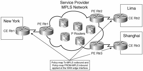
The popularity of MPLS is growing due not only to its ability to provide full-mesh connectivity, but also for its ability to provide differing levels of service for user traffic. This makes it ideal for intraoffice voice and video, in addition to data. However, cooperation is needed between the company and the service provider to ensure consistent treatment of traffic throughout the MPLS network. It is not enough for each site to regulate the way it sends traffic out its own WAN interface, because the service provider routers are also involved in the equation. Consider a simple MPLS network such as the one shown in Figure 8-1.
Figure 8-1. A Simple MPLS Network

In this situation, the company has three sites. Each site has a DS3 WAN link to the MPLS network. Notice the different routers involved. Each company site has an edge routerthe customer edge (CE) router. Each CE router has a DS3 link to a provider edge (PE) router. Within the provider network are multiple provider (P) routers, in addition to other devices. Suppose that a videoconference is held between users in New York and Lima. QoS on the WAN interface of each CE router ensures that the video traffic has the right amount of bandwidth as it leaves the site. However, what if a user at Shanghai starts a large data file download from New York? QoS on the CE3 router, which does not have the video traffic, would not hinder the download. If the PE router to New York does not have QoS controls configured on it, that data traffic could monopolize the bandwidth on the PE1 to CE1 link. At the very least, it would cause jitter and a high drop rate for the videoconference. A better solution is for the MPLS provider to honor the customer DSCP markings and guarantee bandwidth to the video traffic. You must do this at the egress from the PE router to the CE router, and between the P routers within the MPLS network.
MPLS providers typically have a limited number of service levels, and their equipment is programmed to respond to specific DSCP values. Many companies find it easiest to just adopt the service provider marking throughout their own network. But that is not always the best design for every network. Companies that administer their own MPLS network must also plan how to provide the needed levels of service.
Proper planning can make this a lot easier. Keep the MPLS service classes in mind when you plan your internal QoS classes. Consider the company in the example with three large sites connected with an MPLS network. When the IT staff analyzes their traffic, they find IP voice and video conferencingeach with its own signaling, stock market data, SQL database data, e-mail, web browsing, network management, and other miscellaneous traffic. They decide to use the following classes and DSCP values within their network:
- Voice bearer EF
- Video AF41
- Call signaling CS3
- Market data AF32
- Network management AF33 (they also put routing updates, which are marked at CS6, in this class)
- SQL database AF21
- Email AF23
- Best effort (for all other traffic) 0
This company has selected a service provider that has four CoS levels available:
- Real-time EF or CS5
- Mission Critical AF31
- Business Critical AF21
- Other 0
This creates a problem because the company has eight types of traffic that must be provided different QoS levels within its internal network. Clearly, the service provider is not going to change its setup, so the company must map its traffic to the service provider classes before sending it into the MPLS cloud. At each site, it also needs to reclassify the traffic back into its original seven groups and remark it accordingly.
The company decides to place voice, video, and call signaling in the real-time, prioritized class. It would not be a good idea to mix voice and video over a slow link (less than 768 kbps), because video packets tend to be large and thus take longer to serialize onto the link than small voice packets. It might introduce delay and jitter into voice calls if they share a queue. In this example, each site has a DS3 to the MPLS network, so serialization problems are not an issue. Voice retains its EF marking; video and call signaling are marked as CS5.
Market data, network management, and routing traffic go into the second class, Mission Critical. SQL and e-mail traffic go together into the Business Critical class. Both applications use TCP, so WRED is also enabled on the CE routers for this class. All other traffic goes into the Default class. WRED is also enabled on this class at the CE routers.
Voice can retain its current EF marking, but video and call signaling need to be remarked as CS5. Market data, network management, and routing traffic need to be remarked as AF31, and SQL and e-mail traffic need to be remarked as AF21. All other traffic already has a DSCP value of 0, so it does not need to be changed.
Consolidating the classes is fairly easy to do. Example 8-10 shows how to do this. Recall that class maps have two options: match all and match any. This example takes advantage of the match any option to match multiple DSCP values in one class map.
VGateway(config)#class-map match-all TO-MPLS-EF VGateway(config-cmap)#match dscp ef ! VGateway(config)#class-map match-any TO-MPLS-CS5 VGateway(config-cmap)#match dscp af41 VGateway(config-cmap)#match dscp cs3 ! VGateway(config-cmap)#class-map match-any TO-MPLS-AF31 VGateway(config-cmap)#match dscp af32 VGateway(config-cmap)#match dscp af33 VGateway(config-cmap)#match dscp cs6 ! VGateway(config-cmap)#class-map match-any TO-MPLS-AF21 VGateway(config-cmap)#match dscp af21 VGateway(config-cmap)#match dscp af23 |
The basic purpose behind identifying traffic is to configure the router to treat that traffic a certain way. You can manipulate data based on its markings in many ways, such as prioritizing it, guaranteeing bandwidth, policing to a specific bandwidth, dropping it, dropping random packets, or remarking it, as Example 8-11 shows. In the MQC, you do this using a policy map. After you have created the class maps that group the traffic, you use a policy map to change the DSCP values and allocated bandwidth.
VGateway(config)#policy-map TO-MPLS VGateway(config-pmap)#class TO-MPLS-EF VGateway(config-pmap-c)#priority percent 18 VGateway(config-pmap-c)#set dscp ef ! VGateway(config-pmap)#class TO-MPLS-CS5 VGateway(config-pmap-c)#priority percent 15 VGateway(config-pmap-c)#set dscp cs5 ! VGateway(config-pmap-c)#class TO-MPLS-AF31 VGateway(config-pmap-c)#bandwidth percent 12 VGateway(config-pmap-c)#set dscp af31 ! VGateway(config-pmap-c)#class TO-MPLS-AF21 VGateway(config-pmap-c)#bandwidth percent 10 VGateway(config-pmap-c)#set dscp af21 VGateway(config-pmap-c)#random-detect ! VGateway(config-pmap-c)#class class-default VGateway(config-pmap-c)#set dscp 0 VGateway(config-pmap-c)#fair-queue VGateway(config-cmap)#random-detect |
Then you apply this policy map to the WAN interface, outbound, with the following commands:
VGateway(config)#int atm 1/0.110 point-to-point
VGateway(config-subif)#pvc 10/110
VGateway(config-if-atm-vc)#service-policy output TO-MPLS
As a result, traffic from the eight internal QoS classes is mapped to the four classes of the MPLS provider. These same commands are needed on every CE router, applied outbound on the WAN interface. This is fairly easy. However, you must break the traffic back out into the original eight classes when it arrives at its destination CE router. That is a little more involved.
Recall that several types of traffic are sharing the same DSCP value. You must find a way to distinguish between them so that you can group them into the correct class inside the network. In the first group, identifying voice is no problem because it retained its previous marking of EF. Video and call signaling were given the same DSCP value, CS5, and placed into the same class as voice. An access list is used to break out call signaling traffic. Video uses RTP, so you can identify it in that way.
Three types of traffic are in the second group: routing, market data, and network management. The routing protocol used is Border Gateway Protocol (BGP), which you can identify by an access list. The market data uses several different ports, but all traffic is bound either to or from a specific subnet of servers. An access list can also be used to identify them. After those two are broken out, any other traffic with DSCP AF31 must be network management traffic.
The third group consists of SQL and e-mail traffic. The SQL servers share a subnet with the e-mail servers, so a simple access list specifying address is not enough. Fortunately, the Structured Query Language (SQL) and Simple Mail Transfer Protocol (SMTP) ports are both known, so you can use them to identify their respective traffic.
Example 8-12 shows how this might look when you put it all together. In this example, the policy is applied to the CE router at New York, where the servers are located. The access lists at the other sites need to flip the source and destination addresses and ports.
! This is the first group: VGateway(config)#ip access-list extended SCCP VGateway(config-ext-nacl)#permit tcp any any range 2000 2002 ! VGateway(config-ext-nacl)#ip access-list extended RTP VGateway(config-ext-nacl)#permit udp any any range 16383 32767 ! VGateway(config-ext-nacl)#class-map VOICE VGat VGateway(config-cmap)#match dscp ef ! VGateway(config-cmap)#class-map match-all MPLS_CALL_SIG VGateway(config-cmap)#match dscp cs5 VGateway(config-cmap)#match access-group name SCCP ! VGateway(configs-cmap)#class-map match-all MPLS_VIDEO VGateway(config-cmap)#match dscp cs5 VGateway(config-cmap)#match access-group name RTP ! ! This is the second group: VGateway(config)#ip access-list extended BGP VGateway(config-ext-nacl)#permit tcp any any eq bgp VGateway(config-ext-nacl)#permit tcp any eq bgp any ! VGateway(config-ext-nacl)#ip access-list extended Market-Data ! The following is the Market Data server subnet VGateway(config-ext-nacl)#permit ip any 10.1.17.0 0.0.0.255 ! VGateway(config-cmap)#class-map match-all Routing VGateway(config-cmap)#match dscp af31 VGateway(config-cmap)#match access-group name BGP ! VGateway(config-cmap)#class-map match-all Mkt-Data VGateway(config-cmap)#match dscp af31 VGateway(config-cmap)#match access-group name Market-Data ! VGateway(config-cmap)#class-map Network-Mgmt VGateway(config-cmap)#match dscp af31 ! ! This is the third group: VGateway(config)#ip access-list extended SQL VGateway(config-ext-nacl)#permit tcp any any eq 1433 ! VGateway(config-ext-nacl)#ip access-list extended SMTP VGateway(config-ext-nacl)#permit tcp any any eq 25 ! VGateway(config-cmap)#class-map match-all SQL VGateway(config-cmap)#match dscp 21 VGateway(config-cmap)#match access-group name SQL ! VGateway(config-cmap)#class-map match-all EMAIL VGateway(config-cmap)#match dscp 21 VGateway(config-cmap)#match access-group name SMTP |
With the access lists and class maps, you now can classify the traffic incoming from the MPLS cloud into groups that correspond to your company policy. You do this using a policy map, as shown in Example 8-13.
VGateway(config)#policy-map FROM-MPLS VGateway(config-pmap)#class VOICE VGateway(config-pmap-c)#set dscp ef ! VGateway(config-pmap-c)#class MPLS_CALL_SIG VGateway(config-pmap-c)#set dscp cs3 ! VGateway(config-pmap-c)#class MPLS_VIDEO VGateway(config-pmap-c)#set dscp af41 ! VGateway(config-pmap-c)#class Routing VGateway(config-pmap-c)#set dscp cs6 ! VGateway(config-pmap-c)#class Mkt-Data VGateway(config-pmap-c)#set dscp af32 ! VGateway(config-pmap-c)#class Network-Mgmt VGateway(config-pmap-c)#set dscp af33 ! VGateway(config-pmap-c)#class SQL VGateway(config-pmap-c)#set dscp 21 ! VGateway(config-pmap-c)#class EMAIL VGateway(config-pmap-c)#set dscp 23 ! VGateway(config-pmap-c)#class class-default VGateway(config-pmap-c)#set dscp 0 ! VGateway(config-pmap-c)#interface ATM1/0.110 VGateway(config-subif)#pvc 10/110 VGateway(config-if-atm-vc)#service-policy input FROM-MPLS |
You apply the policy map inbound on the interface so that it affects traffic coming in from the MPLS cloud. Notice that policy map FROM-MPLS just sets DSCP values; it does not allocate bandwidth or prioritize traffic. Those tasks must be done at the outbound interfaces.
After the entire configuration is done, each CE router has two service policies on its WAN interface, as shown in Figure 8-2. The outbound policy aggregates the internally used classes of the company into ones that map to the standards of the MPLS provider. It remarks DSCP values where necessary. The inbound policy looks at the traffic coming from the MPLS cloud and then reclassifies and remarks it to comply with the internal QoS policy of the company.
Figure 8-2. Mapping QoS to MPLS Standards
As stated earlier, it is important to thoughtfully plan your QoS strategy. You need to decide how to group traffic and what DSCP value to give to each of those groups. This is not a trivial task.
Link Fragmentation and Interleave
Voice and video traffic are sensitive to delay and jitter. You might recall that the delay target for voice is 150 ms, and for jitter it is 30 ms. LLQ, as described in the previous section, is one way to cut down on delay and jitter. When voice traffic is placed into an LLQ, it is sent out before other traffic. However, suppose that a small voice packet arrives at an interface just after a large data packet has begun being placed on the wire (or serialized). Even though the voice packet is placed in the priority LLQ, transmission of the data packet is not going to stop. The voice packet has to wait. This can be another cause of delay and jitter.
The time it takes for a packet to be placed onto the wire is known as serialization delay. This value varies by speed of the link and size of the packet. Naturally, any size packet takes longer to transmit out a slower interface than a faster one. And the more bits that must be transmitted out an interface, the longer it takes. To meet the requirements for voice, each interface along the path has a target serialization delay of no more than 10 ms. In the LAN, links are fast enough that serialization delay is not a factor. But on WAN links, it can be an issue.
One way to solve this is to break up large data packets into smaller pieces that take no more than 10 ms to serialize, which is known as fragmentation. Then voice packets can be transmitted between each piece of the data packet, which is known as interleaving. When combined, the technique is known as Link Fragmentation and Interleave.
You can calculate an approximate value for serialization delay using the following formula:
([packet-size * 8]/link-speed)
Packet size is in bytes, so you multiply by 8 to convert it to bits. Then you divide that product by the link speed in kbps. For example, the formula for a 1500-byte packet being sent out a T1 interface (1544 kbps) would look like this:
([1500 * 8]/1544 kbps) = 7.8 ms delay
As you can see, 1500 bytes takes less than 10 ms to serialize on a T1 interface. The same number of bytes takes 15.6 ms on a 768-kbps interface, however. As a general rule, fragmentation is not recommended on interfaces of T1 speed or greater. It can be helpful on lower-speed interfaces, if they tend to carry large data packets along with voice.
This leads to the question of what size the fragments should be. Tables are available in QoS texts detailing this, but you can also estimate the correct fragment size. At 64 kbps, it takes about 10 ms to serialize 80 bytes. You can use this fact to calculate fragment sizefor instance, a 256-kbps link is four times a 64 kbps one. So the packet size can be four times 80 bytes, or 320 bytes.
Fragmentation is configured in different ways depending on the type of interface. You can do it on a leased line by using Multilink PPP (MLP), on a Frame Relay circuit by using FRF.12, on a Frame Relay circuit by using Multilink PPP over Frame Relay (MLPoFR), and with ATM by using Multilink PPP over ATM (MLPoATM). (An alternative for both Frame Relay and ATM is to use separate PVCs for voice.)
Multilink PPP
Multilink PPP was created to allow multiple PPP links to be treated as one, for load balancing and ease of administration. You can also use it with a single PPP link, as the example that follows shows. One good thing about using MLP is that you do not have to figure out the desired fragment sizePPP does that for you. You only have to specify the desired serialization delay value. Configuration is done with both a logical and a physical interface. Configuring MLP involves the following steps:
|
Step 1. |
Create a logical Multilink interface. Notice that logical configurations, such as the IP address, service policy, and bandwidth, are all configured on the Multilink interface. VGateway(config-if)#interface multilink1 VGateway(config-if)#ip address 172.18.1.1 255.255.255.252 VGateway(config-if)#service-policy output VOICE-VIDEO VGateway(config-if)#bandwidth 768 |
|
Step 2. |
Enable Multilink PPP, and associate the interface with a Multilink group. Configure the desired delay on the Multilink interface. VGateway(config-if)#ppp multilink VGateway(config-if)#ppp multilink group 1 VGateway(config-if)#ppp multilink fragment-delay 10 |
|
Step 3. |
Configure interleaving on the Multilink interface. VGateway(config-if)#ppp multilink interleave |
|
Step 4. |
At the physical PPP interface, configure PPP encapsulation, and enable PPP Multilink. VGateway(config-if)#int s 0/0 VGateway(config-if)#encapsulation ppp VGateway(config-if)#ppp multilink |
|
Step 5. |
Place the physical interface into the Multilink group that is associated with the Multilink interface created earlier. VGateway(config-if)#ppp multilink group 1 |
A useful verification command for MLP is show interface multilink interface-number. Example 8-14 shows the output from this command. Link control protocol (LCP) and multilink must both be open for the interface to be active. Under the Output queue line, which is highlighted, you can see the number of interleaves performed.
|
[View full width] VGateway#show interface multilink 1 Multilink1 is up, line protocol is up Hardware is multilink group interface Internet address is 172.18.1.1/30 MTU 1500 bytes, BW 768 Kbit, DLY 100000 usec, reliability 255/255, txload 9/255, rxload 9/255 Encapsulation PPP, LCP Open, multilink Open Open: CDPCP, IPCP, loopback not set Keepalive set (10 sec) DTR is pulsed for 2 seconds on reset Last input 00:00:04, output never, output hang never Last clearing of "show interface" counters 01:21:31 Input queue: 0/75/0/0 (size/max/drops/flushes); Total output drops: 0 Queueing strategy: Class-based queueing Output queue: 0/1000/64/0/138 (size/max total/threshold/drops/interleaves) Conversations 0/2/256 (active/max active/max total) Reserved Conversations 0/0 (allocated/max allocated) . . .
|
You must do this configuration on both sides of the link for fragmentation and interleave to work properly. One caveat is that any traffic in an LLQ will not be fragmented. Because video packets can go up to 1500 bytes in size, do not place video in the LLQ on slow links.
If you must run video through an interface with less than T1 bandwidth, put it in a class-based queue and assign bandwidth to it.
Frame Relay FRF.12 Fragmentation
FRF.12 is a standards-based way to do fragmentation on Frame Relay links. This standard allows you to fragment and interleave long frames with smaller frames at Layer 2. Frame Relay does not look into the packets to see whether traffic is voice or data. It fragments all packets larger than the specified size, regardless of what payload they carry. Therefore, be sure to configure a fragment size larger than the biggest voice traffic, with headers included.
Fragmentation is configured at the PVC level and applied to all traffic within that PVC. If multiple PVCs share the same physical interface, configure fragmentation on all of them because they share the same transmit ring at the interface. If any PVCs send large unfragmented frames, it could delay the voice traffic. Configure fragmentation on routers at both ends of the PVC, because it is end to end. Frames are fragmented at one router, and reassembled by the router on the other end of the virtual circuit. A special FRF.12 header is put on traffic from the PVC when fragmentation is configured.
When you are sending VoFR, shape the traffic from each PVC to avoid drops or delays from buffering within the provider cloud. Frame Relay traffic shaping (FRTS) causes the router to control the amount of traffic sent out the interface so that it conforms to the committed information rate (CIR) of each PVC. The traditional way to configure shaping is to place the commands under a Frame Relay map class. However, current versions of the Cisco IOS can do class-based FRTS. Configuring class-based Frame Relay fragmentation and shaping involves the following steps:
|
Step 1. |
Configure a policy map that puts voice in an LLQ and sets policies for other traffic as desired. Be sure that the total bandwidth allocated does not exceed the circuit CIR. VGateway(config)#policy-map LLQ VGateway(config-pmap)#class VOICE VGateway(config-pmap-c)#priority 128 |
|
Step 2. |
Configure a second policy map. Configure traffic shaping parameters under the default class. In the following output, the first number is the configured CIR, in bits per second. Cisco recommends configuring the CIR to be 95 percent of the actual CIR to allow for overhead. The second number is the number of bits allowed per interval. Set this to the CIR/100, which forces that interval to be 10 ms. The last number is the excess burst (Be) allowed. Set this to 0 when sending VoIP over Frame Relay. Gateway(config-pmap-c)#policy-map SHAPE VGateway(config-pmap)#class class-default VGateway(config-pmap-c)#shape average 729600 7296 0 |
|
Step 3. |
Associate the first policy map with the second under the default class. VGateway(config-pmap-c)#service-policy LLQ |
|
Step 4. |
Configure a Frame Relay map class. Configure the fragmentation parameter under this map class and associate the service policy with it. Set the fragment size to 960 by using the method given in the "Link Fragmentation and Interleave" section earlier in this chapter. Take advantage of the fact that at 64 kbps, it takes about 10 ms to serialize 80 bytes. The link speed in this example is 768 kbps. Thus, 768 divided by 64 equals 12. Multiplying 80 bytes times 12 gives you a fragment size of 960 bytes. VGateway(config)#map-class frame-relay LFI-SHAPE VGateway(config-map-class)#frame-relay fragment 960 VGateway(config-map-class)#service-policy output SHAPE |
|
Step 5. |
Associate the map class with a PVC: VGateway(config)#interface s0/0.112 point-to-point VGateway(config-subif)#frame-relay interface-dlci 112 VGateway(config-fr-dlci)#class LFI-SHAPE |
You can verify the configuration by the output of the show policy interface command, as follows in Example 8-15.
|
[View full width] VGateway#show policy interface s0/0.112 Serial0/0.112: DLCI 112 - Service-policy output: SHAPE Class-map: class-default (match-any) 0 packets, 0 bytes 5 minute offered rate 0 bps, drop rate 0 bps Match: any Traffic Shaping Target/Average Byte Sustain Excess Interval Increment Rate Limit bits/int bits/int (ms) (bytes) 729600/729600 1825 7296 7296 10 912 Adapt Queue Packets Bytes Packets Bytes Shaping Active Depth Delayed Delayed Active - 0 0 0 0 0 no Service-policy : LLQ Class-map: VOICE (match-all) 0 packets, 0 bytes 5 minute offered rate 0 bps, drop rate 0 bps Match: access-group name RTP Queueing Strict Priority Output Queue: Conversation 72 Bandwidth 128 (kbps) Burst 3200 (Bytes) (pkts matched/bytes matched) 0/0 (total drops/bytes drops) 0/0 Class-map: class-default (match-any) 0 packets, 0 bytes 5 minute offered rate 0 bps, drop rate 0 bps Match: any
|
The show frame-relay fragment command lets you monitor the fragmentation occurring, as shown in Example 8-16. You can obtain more detailed information by specifying an interface after the command.
|
[View full width] VGateway#show frame-relay fragment interface dlci frag-type size in-frag out-frag dropped-frag Se0/0.112 112 end-to-end 960 0 0 0
|
Frame Relay Fragmentation Using MLPoFR
Link fragmentation and interleave can be done over Frame Relay using MLPoFR. Instead of creating a Multilink interface, the logical interface is called a Virtual-Template. Example 8-17 shows the configuration needed. You create a Virtual-Template interface and give almost the same configuration as shown in the Multilink interface example in the preceding "Multilink PPP" section. Fragmentation delay is specified, as is interleaving. The service policy LLQ is associated with this Virtual-Template interface, not the physical interface.
|
[View full width] VGateway(config)#interface virtual-template1 VGateway(config-if)# 00:10:39: %LINK-3-UPDOWN: Interface Virtual-Template1, changed state to down VGateway(config-if)#bandwidth 768 VGateway(config-if)#ip address 172.18.1.1 255.255.255.252 VGateway(config-if)#ppp multilink VGateway(config-if)#ppp multilink fragment delay 10 VGateway(config-if)#ppp multilink interleave VGateway(config-if)#service-policy output LLQ ! VGateway(config-if)#map-class frame-relay MLPoFR VGateway(config-map-class)#frame-relay cir 729600 VGateway(config-map-class)#frame-relay bc 7296 VGateway(config-map-class)#frame-relay be 0 VGateway(config-map-class)#no frame-relay adaptive-shaping becn ! VGateway(config-map-class)#)#interface s0/0 VGateway(config-if)#encapsulation frame-relay VGateway(config-if)#frame-relay traffic-shaping ! VGateway(config-if)#interface s0/0.112 point-to-point VGateway(config-subif)#frame-relay interface-dlci 112 ppp virtual-template1 Class Based Weighted Fair Queueing will be applied only to the Virtual-Access interfaces associated with an MLP bundle. VGateway(config-fr-dlci)# 00:38:48: %LINK-3-UPDOWN: Interface Virtual-Access2, changed state to up VGateway(config-fr-dlci)#class MLPoFR
|
A Frame Relay map class, MLPoFR, is configured with shaping parameters. Under that map class, the CIR is set to 95 percent of the link speed of 768 kbps to allow for overhead. Committed burst (Bc) is set to link-speed/100 to force the burst interval to be 10 ms. No Be is allowed. Adaptive traffic shaping in response to backward explicit congestion notification (BECN) frames is disabled.
Enable Frame Relay traffic shaping on the physical interface and apply the map class to the PVC. Notice the command to associate that PVC with the Virtual-Template interface: frame-relay interface-dlci dlci-number ppp virtual-template1. When MLPoFR is configured, the router automatically creates two additional logical interfaces: Virtual-Access1 and Virtual-Access2. (Notice in the example the message saying that interface Virtual-Access2 is up.) Virtual-Access1 is a logical PPP interface, and Virtual-Access2 is a logical Multilink PPP Bundle interface. You can verify this by looking at the output from a show interface command. The router messages shown are normal.
MLPoATM
You can also use MLP with an ATM PVC. Using MLPoATM allows ATM traffic to be fragmented and interleaved, something that ATM itself cannot accomplish. The most frequently used ATM adaptation layers assume that cells will arrive in the correct order, so they do not place a sequence number on the cells. Interleaving would make the cells arrive out of order. MLP handles the fragmenting, interleaving, sequence numbering, and reordering of the cells transparently to ATM.
When using MLPoATM, a Virtual-Template interface is created with the same commands as with MLPoFR. As a reminder, Example 8-18 shows the configuration.
VGateway#show run interface virtual-template1 interface Virtual-Template1 bandwidth 768 ip address 172.18.1.1 255.255.255.252 ppp multilink ppp multilink fragment delay 10 ppp multilink interleave service-policy output LLQ VGateway(config)#interface atm 1/0 VGateway(config-if)#bandwidth 768 ! VGateway(config-if)#interface atm 1/0.110 point-to-point VGateway(config-subif)#pvc 10/110 VGateway(config-if-atm-vc)#vbr-nrt 768 768 VGateway(config-if-atm-vc)#protocol ppp virtual-template1 VGateway(config-if-atm-vc)#tx-ring-limit 3 |
There is no equivalent to a Frame-Relay map class needed to specify shaping parameters; instead, you configure shaping parameters under the virtual circuit configuration, as shown in Example 8-18. The example PVC uses variable bit rate, nonreal-time (VBR-nrt). The first number is the peak cell rate (PCR), the maximum rate at which you expect to transmit traffic. The second number is the sustainable cell rate (SCR), which is the bandwidth of the virtual circuit. Setting the PCR and SCR to the same value effectively eliminates bursts, causing traffic to be shaped to a constant rate.
If you are experiencing excessive delay when using VoIP with ATM, try lowering the size of the interface transmit ring. Generally, setting the transmit ring size to 3 or 4 particles works well for voice. You do that under the virtual circuit configuration, as shown in Example 8-18.
Commands to verify the configuration include show atm vc and show policy-map interface.
Compression
Another way to lower serialization delay values is to send smaller packets. The payload in voice packets tends to be fairly small. However, each packet has to carry an IP header, a UDP header, and an RTP header that totals 40 bytes of overhead. When voice is sent across a WAN, it is usually compressed using G729, with a payload of 20 bytes. Thus, the headers are twice the size of the payload. Most of the header information in any given conversation is the same, so it can be reliably compressed. Compressed RTP (cRTP) compresses the IP, UDP, and RTP headers; it does not change the payload. With cRTP you can usually reduce the three headers to 2 bytes when checksum data is not sent, and 4 bytes when checksums are used. As you can imagine, this is especially helpful on slow links.
You can enable RTP compression on a Frame Relay, high-level data link control (HDLC), PPP, or MLP link. It is configured either at the interface level, on a particular virtual circuit, or for a class of traffic using the MQC. You must enable RTP compression on routers at both ends of a link, because each router in the path needs to uncompress the headers to know how to route the data.
Use cRTP with slow links, small voice payloads, and a need to save bandwidth. It is typically not needed on links over 2 Mbps in speed. Compression and decompression do use router resources, with more resources used the more calls you have. The trade-off in router performance is usually not worth the gain in bandwidth with link speeds over 2 Mbps. Understand that cRTP only compresses the headers for RTP traffic, not other types of data. If fast-switching or Cisco Express Forwarding (CEF) is enabled on the interface, compression is done on these paths. If neither is enabled on the interface, traffic that needs to be compressed is process switched.
To enable CRTP on an HDLC or PPP serial interface, use the following command under the physical interface configuration:
ip rtp header-compression [passive]
If you include the optional passive keyword, the router does CRTP only if it receives compressed packets.
To enable CRTP on a Frame Relay interface, use the following command:
frame-relay ip rtp header-compression [passive]
You can configure the preceding command either under the physical interface configuration or under the subinterface.
If this command is given on the physical Frame Relay interface, all PVCs that are associated with that interface inherit it.
MQC class-based compression allows more granular control of RTP compression. It is configured in a policy map and applies only to RTP traffic in the specific class(es) where it is enabled. For instance, in the following commands, RTP header compression is enabled for all traffic in the Voice class. If the rtp keyword is not specified, both RTP and TCP header compression are done. You should also configure the gateway to place this traffic in the LLQ.
VGateway(config)#policy-map VOICE-VIDEO
VGateway(config-pmap)#class Voice
VGateway(config-pmap-c)#compression header ip rtp
Then you can apply the policy outbound to an interface, virtual circuit, Frame Relay map class, or virtual interface. You can verify your configuration with the show policy-map and show policy interface commands, as shown in Example 8-19.
Note
For simplicity, only relevant output is displayed in Example 8-19.
VGateway#show policy VOICE-VIDEO Policy Map VOICE-VIDEO Class Voice Strict Priority Bandwidth 15 (%) compress: header ip rtp VGateway# VGateway#show policy interface s0/0 Serial0/0 Service-policy output: VOICE-VIDEO Class-map: Voice (match-all) 2153 packets, 137792 bytes 5 minute offered rate 10000 bps, drop rate 0 bps Match: dscp ef (46) Queueing Strict Priority Output Queue: Conversation 264 Bandwidth 15 (%) Bandwidth 231 (kbps) Burst 5775 (Bytes) (pkts matched/bytes matched) 2152/36584 (total drops/bytes drops) 0/0 compress: header ip rtp UDP/RTP compression: Sent: 2152 total, 2147 compressed, 101208 bytes saved, 36584 bytes sent |
AutoQos
Cisco has an AutoQoS feature that you can enable. When enabled, this feature configures QoS policies for the device in accordance with Cisco best practices. It is useful for network administrators who do not have in-depth knowledge of QoS techniques, such as those discussed in this chapter, or for those who need to deploy QoS quickly.
AutoQoS has the following features when used at a WAN voice gateway router:
- It uses the MQC.
- It creates class maps to classify voice-bearer and voice-control traffic, in addition to other traffic.
- It creates policy maps that place voice traffic in an LLQ and guarantee bandwidth to voice control traffic.
- Frame Relay traffic shaping is configured for Frame Relay links.
- Link Fragmentation and Interleaving (LFI) and RTP header compression are configured for links under 768 kbps.
- When you are using LFI, any IP address that is configured under the subinterface is automatically moved to the multilink or Virtual-Template interface.
- It supports Frame Relay, ATM, Frame Relay-to-ATM Internetworking, PPP, and HDLC links.
- It can send SNMP and SYSLOG notices for such things as VoIP packet drops.
AutoQos is configured on a WAN interface, subinterface, or PVC with the following command:
auto qos voip [trust] [fr-atm]
The optional keyword trust tells the router to trust the DSCP markings that are already on the traffic. The default is not to trust those markings, but to remark traffic based on its type. AutoQos uses Network-Based Application Recognition (NBAR) to determine types of traffic. The optional fr-atm keyword is used with low-speed Frame Relay PVCs that participate in Frame Relay-to-ATM Internetworking. You must manually configure bandwidth on the interface or subinterface when you are using AutoQoS.
Using AutoQos can be helpful, but a basic understanding of good QoS practices is still important. You might need to tweak the automatic configuration to suit the exact needs of your company. In addition, it is always good to understand what is happening in your network.
Providing Fax and Modem Services |
Part I: Voice Gateways and Gatekeepers
Gateways and Gatekeepers
- Gateways and Gatekeepers
- The Role of Voice Gateways
- The Role of Voice Gatekeepers
- The Role of IP-to-IP Gateways
- Introduction to Voice Protocols
- Call Control Agents
- Deployment Scenarios
- Case Study: Introduction
- Chapter Review Questions
Part II: Gateways
Media Gateway Control Protocol
- Media Gateway Control Protocol
- Introduction to MGCP
- MGCP Operation
- Call Flow with MGCP
- Dial Plan Considerations
- Implementing MGCP Gateways
- Securing MGCP Gateways
- Troubleshooting Tools
- Case Study: Configuring an MGCP Gateway
- Review Questions
H.323
- H.323
- H.323 Specifications
- H.323 Network Components
- Call Flow
- H.323 Protocol Pros and Cons
- When to Use H.323
- Dial Plan Considerations
- Implementing H.323 Gateways
- Securing H.323 Gateways
- Troubleshooting Tools
- Case Study: Configuring an H.323 Gateway
- Review Questions
Session Initiation Protocol
- Session Initiation Protocol
- Description of SIP
- SIP Call Flow
- SIP Pros and Cons
- When to Use SIP
- Dial Plan Considerations
- Implementing SIP Gateways
- Securing SIP Gateways
- Allowing H.323 to SIP Connections
- Troubleshooting Tools
- Case Study: Configuring SIP Between a Gateway and CallManager 5.x
- Review Questions
Circuit Options
Connecting to the PSTN
- Connecting to the PSTN
- PSTN Circuit Selection Overview
- Analog Trunks
- Digital Trunks
- Case Study: Add an E1 R2 Connection to the Leeds Gateway
- Review Questions
Connecting to PBXs
- Connecting to PBXs
- Analog Trunks
- Digital Trunks
- Configuring Transparent Common Channel Signaling
- Case Study: Implementing a Cisco Voice Gateway at the Shanghai Office
- Review Questions
Connecting to an IP WAN
- Connecting to an IP WAN
- Applications for Connecting to an IP WAN
- Design Considerations
- Quality of Service
- Providing Fax and Modem Services
- Security
- Case Study: Using a T1 Link as a Tie Line
- Review Questions
Dial Plans
- Dial Plans
- Numbering Plans
- Overlapping Numbering Plans
- Building a Scalable Dial Plan
- Dial Peers
- Dial Peer Matching
- Case Study: Configuring PSTN Access
- Review Questions
Digit Manipulation
- Digit Manipulation
- Basic Digit Manipulation
- Number Expansion
- Voice Translation Rules and Profiles
- Manipulating Caller ID
- Order of Operation in Digit Manipulation
- Troubleshooting Digit Manipulation
- Case Study
- Review Questions
Influencing Path Selection
- Influencing Path Selection
- Hunt Groups
- Using Trunk Groups
- Tail-End Hop-Off
- Call Admission Control
- POTS-to-POTS Call Routing Considerations
- Case Study: Implementing Gateway-Controlled RSVP
- Review Questions
Configuring Class of Restrictions
- Configuring Class of Restrictions
- COR Overview
- COR Operation
- Implementing COR
- Assigning COR Lists with SRST
- Assigning COR Lists with Cisco CallManager Express
- Restricting Inbound Calls
- Case Study: Implementing COR for Miami
- Review Questions
SRST and MGCP Gateway Fallback
- SRST and MGCP Gateway Fallback
- SRST Overview
- Configuring SRST
- Dial Plan Considerations
- SRST Features
- SIP SRST
- Call Preservation
- Secure SRST
- MGCP Gateway Fallback
- Configuring MGCP Gateway Fallback
- Verifying and Troubleshooting SRST
- Verifying and Troubleshooting MGCP Gateway Fallback
- Case Study: Integrating SRST with an Analog Voice-Mail System
- Review Questions
DSP Resources
- DSP Resources
- Need for DSP Resources
- Determining the DSP Resources Required
- Configuring DSP Resources
- Transcoding for CallManager Express
- Case Study: Add DSP Resources to the Miami Gateway
- Review Questions
Using Tcl Scripts and VoiceXML
- Using Tcl Scripts and VoiceXML
- Tcl IVR and VoiceXML Application Overview
- Sample Applications
- Downloading Tcl Scripts from Cisco.com
- Configuring the Gateway to Use a Tcl Script
- Implementing the AA Tcl Script
- Creating Audio Files
- Restrictions and Caveats
- Case Study: Implementing ACD Application
- Review Questions
Part III: Gatekeepers
Deploying Gatekeepers
- Deploying Gatekeepers
- Gatekeeper Functionality
- Gatekeeper Signaling
- E.164 Number Resolution
- Call Admission Control
- Gatekeeper Deployment Models
- Gatekeepers with CallManager
- Security with Gatekeepers
- Review Questions
Gatekeeper Configuration
- Gatekeeper Configuration
- Configuring Basic Gatekeeper Functionality
- Multiple Gatekeeper Configurations
- Configuring Directory Gatekeepers
- Troubleshooting Gatekeepers
- CallManager and Gatekeepers
- Gatekeeper Redundancy
- Configuring Resource Availability Indicator
- Configuring Gatekeeper Security
- Case Study: Deploying Gatekeepers to Assist in Migration to VoIP
- Review Questions
Part IV: IP-to-IP Gateways
Cisco Multiservice IP-to-IP Gateway
- Cisco Multiservice IP-to-IP Gateway
- IP-to-IP Gateway Overview
- Cisco Multiservice IP-to-IP Gateway
- Basic Configuration
- IP-to-IP Gateway Features
- Case Study: Providing Enterprise VoIP Trunking to VoIP Service of the Service Provider
- Review Questions
Appendix A. Answers to Chapter-Ending Review Questions
Index
EAN: 2147483647
Pages: 218
