VPN Server Behind the Firewall
In a more common configuration, the firewall is connected to the Internet and the VPN server is an intranet resource that is connected to the perimeter network, also known as a demilitarized zone (DMZ) or screened subnet. The perimeter network is an IP network segment that contains resources that are available to Internet users, such as Web and FTP servers. The VPN server has an interface on both the perimeter network and the intranet. In this approach, the firewall must be configured with input and output filters on its Internet interface that allow the passing of tunnel maintenance traffic and tunneled data to the VPN server. Additional filters can allow the passing of traffic to Web, FTP, and other types of servers on the perimeter network. For an added layer of security, the VPN server should also be configured with PPTP or L2TP/IPSec packet filters on its perimeter network interface.
The firewall in this configuration is acting as a filter for Internet traffic and can confine the incoming and outgoing traffic to the specific resources on the perimeter network, perform intrusion attempt detection, prevent denial of service (DoS) attacks, and perform other functions.
Because the firewall does not have the encryption keys for each VPN connection, it can filter only on the plaintext headers of the tunneled data. In other words, all tunneled data passes through the firewall. This is not a security concern, however, because the VPN connection requires an authentication process that prevents unauthorized access beyond the VPN server.
Figure B-2 shows the VPN server on the perimeter network, behind the firewall.
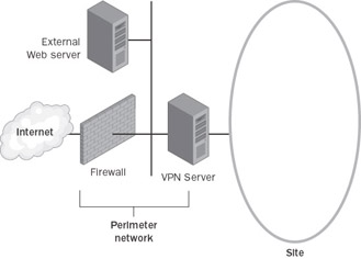
Figure B-2: The VPN server on the perimeter network, behind the firewall.
For both the Internet and network perimeter interfaces on the firewall, configure the following input and output filters using the firewall’s configuration software.
Packet Filters for PPTP
Separate input and output packet filters can be configured on the Internet interface and the perimeter network interface.
Filters on the Internet Interface
Configure the following input packet filters on the Internet interface of the firewall to allow the following types of traffic:
-
Destination IP address of the VPN server’s perimeter network interface and TCP destination port of 1723 (0x6BB).
This filter allows PPTP tunnel management traffic to the VPN server.
-
Destination IP address of the VPN server’s perimeter network interface and IP Protocol ID of 47 (0x2F).
This filter allows PPTP tunneled data to the VPN server.
-
Destination IP address of the VPN server’s perimeter network interface and TCP source port of 1723 (0x6BB).
This filter is required only when the VPN server is acting as a VPN client (a calling router) in a site-to-site VPN connection. This filter should be used only in conjunction with PPTP packet filters as described in the “VPN Server in Front of the Firewall” section and configured on the VPN server’s network perimeter interface. By allowing all traffic to the VPN server from TCP port 1723, there exists the possibility of network attacks from sources on the Internet that use this port.
Configure the following output filters on the Internet interface of the firewall to allow the following types of traffic:
-
Source IP address of the VPN server’s perimeter network interface and TCP source port of 1723 (0x6BB).
This filter allows PPTP tunnel management traffic from the VPN server.
-
Source IP address of the VPN server’s perimeter network interface and IP Protocol ID of 47 (0x2F).
This filter allows PPTP tunneled data from the VPN server.
-
Source IP address of the VPN server’s perimeter network interface and TCP destination port of 1723 (0x6BB).
This filter is required only when the VPN server is acting as a VPN client (a calling router) in a site-to-site VPN connection. This filter should be used only in conjunction with PPTP packet filters as described in the “VPN Server in Front of the Firewall” section and configured on the VPN server’s network perimeter interface. By allowing all traffic from the VPN server to TCP port 1723, there exists the possibility of network attacks from sources on the Internet using this port.
Filters on the Perimeter Network Interface
Configure the following input filters on the perimeter network interface of the firewall to allow the following types of traffic:
-
Source IP address of the VPN server’s perimeter network interface and TCP source port of 1723 (0x6BB).
This filter allows PPTP tunnel management traffic from the VPN server.
-
Source IP address of the VPN server’s perimeter network interface and IP Protocol ID of 47 (0x2F).
This filter allows PPTP tunneled data from the VPN server.
-
Source IP address of the VPN server’s perimeter network interface and TCP destination port of 1723 (0x6BB).
This filter is required only when the VPN server is acting as a VPN client (a calling router) in a site-to-site VPN connection. This filter should be used only in conjunction with PPTP packet filters as described in the “VPN Server in Front of the Firewall” section and configured on the VPN server’s network perimeter interface. By allowing all traffic from the VPN server to TCP port 1723, there exists the possibility of network attacks from sources on the Internet using this port.
Configure the following output packet filters on the perimeter network interface of the firewall to allow the following types of traffic:
-
Destination IP address of the VPN server’s perimeter network interface and TCP destination port of 1723 (0x6BB).
This filter allows PPTP tunnel management traffic to the VPN server.
-
Destination IP address of the VPN server’s perimeter network interface and IP Protocol ID of 47 (0x2F).
This filter allows PPTP tunneled data to the VPN server.
-
Destination IP address of the VPN server’s perimeter network interface and TCP source port of 1723 (0x6BB).
This filter is required only when the VPN server is acting as a VPN client (a calling router) in a site-to-site VPN connection. This filter should be used only in conjunction with PPTP packet filters as described in the “VPN Server in Front of the Firewall” section and configured on the VPN server’s network perimeter interface. By allowing all traffic to the VPN server from TCP port 1723, there exists the possibility of network attacks from sources on the Internet using this port.
Packet Filters for L2TP/IPSec
Separate input and output packet filters can be configured on the Internet interface and the perimeter network interface.
Filters on the Internet Interface
Configure the following input packet filters on the Internet interface of the firewall to allow the following types of traffic:
-
Destination IP address of the VPN server’s perimeter network interface and UDP destination port of 500 (0x1F4).
This filter allows IKE traffic to the VPN server.
-
Destination IP address of the VPN server’s perimeter network interface and UDP destination port of 4500 (0x1194).
This filter allows IPSec NAT-T traffic to the VPN server.
-
Destination IP address of the VPN server’s perimeter network interface and IP Protocol ID of 50 (0x32).
This filter allows IPSec ESP traffic to the VPN server.
Configure the following output packet filters on the Internet interface of the firewall to allow the following types of traffic:
-
Source IP address of the VPN server’s perimeter network interface and UDP source port of 500 (0x1F4).
This filter allows IKE traffic from the VPN server.
-
Source IP address of the VPN server’s perimeter network interface and UDP source port of 4500 (0x1194).
This filter allows IPSec NAT-T traffic from the VPN server.
-
Source IP address of the VPN server’s perimeter network interface and IP Protocol ID of 50 (0x32).
This filter allows IPSec ESP traffic from the VPN server.
There are no filters required for L2TP traffic at the UDP port of 1701. All L2TP traffic at the firewall, including tunnel maintenance and tunneled data, is encrypted as an IPSec ESP payload.
Filters on the Perimeter Network Interface
Configure the following input packet filters on the perimeter network interface of the firewall to allow the following types of traffic:
-
Source IP address of the VPN server’s perimeter network interface and UDP source port of 500 (0x1F4).
This filter allows IKE traffic from the VPN server.
-
Source IP address of the VPN server’s perimeter network interface and UDP source port of 4500 (0x1194).
This filter allows IPSec NAT-T traffic from the VPN server.
-
Source IP address of the VPN server’s perimeter network interface and IP Protocol ID of 50 (0x32).
This filter allows IPSec ESP traffic from the VPN server.
Configure the following output packet filters on the perimeter network interface of the firewall to allow the following types of traffic:
-
Destination IP address of the VPN server’s perimeter network interface and UDP destination port of 500 (0x1F4).
This filter allows IKE traffic to the VPN server.
-
Destination IP address of the VPN server’s perimeter network interface and UDP destination port of 4500 (0x1194).
This filter allows IPSec NAT-T traffic to the VPN server.
-
Destination IP address of the VPN server’s perimeter network interface and IP Protocol ID of 50 (0x32).
This filter allows IPSec ESP traffic to the VPN server.
There are no filters required for L2TP traffic at the UDP port of 1701. All L2TP traffic at the firewall, including tunnel maintenance and tunneled data, is encrypted as an IPSec ESP payload.
EAN: 2147483647
Pages: 128
- Step 2.1 Use the OpenSSH Tool Suite to Replace Clear-Text Programs
- Step 3.1 Use PuTTY as a Graphical Replacement for telnet and rlogin
- Step 3.3 Use WinSCP as a Graphical Replacement for FTP and RCP
- Step 3.4 Use PuTTYs Tools to Transfer Files from the Windows Command Line
- Step 4.5 How to use OpenSSH Passphrase Agents