Motherboard Power Connectors
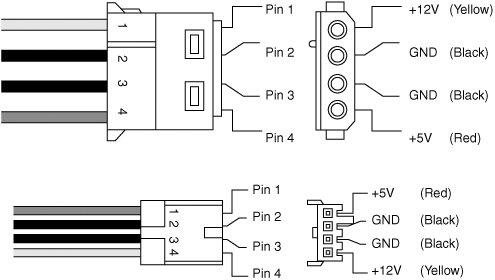
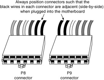
| Every PC power supply has connectors that attach to the motherboard, providing power to the motherboard; processor; memory; chipset; integrated components such as video, LAN, USB, and FireWire; and any cards plugged in to bus slots. These connectors are very importantnot only are these the main conduit through which power flows to your system, but attaching these connectors improperly can have a devastating effect on your PC, including burning up both your power supply and motherboard. Just as with the mechanical shape of the power supply, these connectors are usually designed to conform to one of several industry-standard specifications, which dictate the types of connectors used as well as the pinouts of the individual wires and terminals. Unfortunately, just as with the mechanical form factors, some PC manufacturers use power supplies with custom connectors or, worse yet, use standard connector types but with modified (incompatible) pinouts (meaning the signals and voltages are rearranged from standard specifications). Plugging a power supply with an incompatible pinout into a motherboard that uses a standard pinout (or vice versa) usually results in the destruction of either the board or the power supplyor both. Just as I insist on industry-standard mechanical form factors in my systems, I also want to ensure that they use industry-standard connectors and pinouts. By only purchasing components that conform to industry standards, I can ensure the greatest flexibility and lowest cost for future upgrades and repairs. Two main sets of motherboard power connectors have been used over the years: what I would call AT/LPX type and the ATX type. Each of these has minor variations; for example, the ATX type has evolved over the years, with new connectors coming (and some going) and modifications to existing connectors. The following sections detail the motherboard power connectors used by various types of industry-standard (and some not-so-standard) power supplies. AT/LPX Power Supply ConnectorsIndustry standard PC, XT, AT, Baby-AT, and LPX motherboards all use the same type of main power supply connectors. AT/LPX power supplies feature two main power connectors (P8 and P9), each with six pins that attach the power supply to the motherboard. The terminals used in these connectors are rated to handle up to 5 amps at up to 250V (even though the maximum used in a PC is +12V). These two connectors are shown in Figure 19.20. Figure 19.20. AT/LPX main P8/P9 (sometimes also called P1/P2) power connectors. All AT/LPX power supplies that use the P8 and P9 connectors have them installed end to end so that the two black wires (ground connections) on both power connectors are next to each other when properly plugged in. Note the designations "P8" and "P9" are not fully standardized, although most use those designations because that is what IBM stamped on the originals. Some power supplies have them labeled as P1/P2 instead. Because these connectors usually have a clasp that prevents them from being inserted backward on the motherboard's pins, the major concern is getting the two connectors in the correct orientation side by side and also not offsetting by one or more pins side to side. Following the black-to-black rule and ensuring they are on-center keeps you safe. You must take care to ensure that no remaining unconnected motherboard pins exist between or on either side of the two connectors after you install them. A properly installed connector connects to and covers every motherboard power pin. If any power pins are showing on either side of or between the connectors, the entire connector assembly is installed incorrectly, which can result in catastrophic failure for the motherboard and everything plugged in to it at the time of power-up. Figure 19.21 shows the P8 and P9 connectors (sometimes also called P1/P2) in their proper orientation when connecting them to a motherboard. Figure 19.21. The P8/P9 power connectors (sometimes also called P1/P2) that connect an AT/LPX power supply to the motherboard. Table 19.4 shows typical AT/LPX power supply connections.
Tip Although older PC/XT power supplies do not have any connection at connector P8 pin 2, you still can use them on AT-type motherboards, or vice versa. The presence or absence of the +5V on that pin has little or no effect on system operation because the remaining +5V wires can usually carry the load. Note that all the AT/LPX-type power supplies use the same connectors and pin configurations; there were never any non-standard variations to my knowledge. ATX and ATX12V 1.x Motherboard Power ConnectorsPower supplies conforming to the original ATX and ATX12V 1.x form factor standards or variations thereof use the following three motherboard power connectors:
The main power connector is always required, but the other two are optional depending on the application. Consequently, a given ATX or ATX12V power supply can have up to four different combinations of connectors, as listed here:
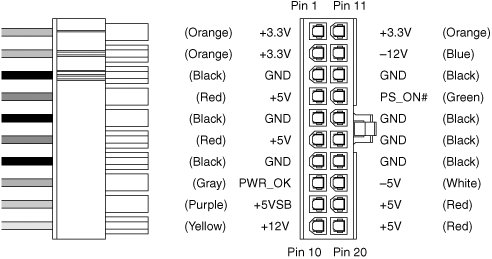
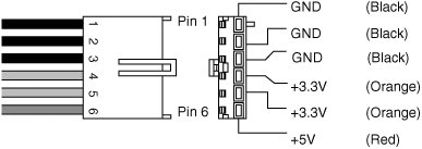
The most common varieties are those including the main only and those with the main and +12V connectors. Most motherboards that use the +12V connector do not use the auxiliary connector, and vice versa. 20-pin Main Power ConnectorThe 20-pin main power connector is standard for all power supplies conforming to the ATX and ATX12V 1.x power supply form factors and consists of a Molex Mini-Fit Jr. connector housing with female terminals. For reference, the connector is Molex part number 39-01-2200 (or equivalent) and the standard terminals are part number 5556 (see Figure 19.22). This is a 20-pin keyed connector with pins configured as shown in Table 19.5. The colors for the wires listed are those the ATX standard recommends; however, to enable them to vary from manufacturer to manufacturer, they are not required for compliance to the specification. I like to show these connector pinouts in a wire side view, which shows how the pins are arranged looking at the back of the connector (from the wire and not the terminal side). This is because it shows how they would be oriented if you were back-probing the connector with the connector plugged in. Figure 19.22. ATX-style 20-pin motherboard main power connector, perspective view.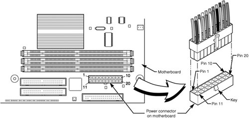
Figure 19.23 shows a view of the connector as if you were looking at it facing the terminal side. Figure 19.23. ATX/NLX 20-pin main power connector, terminal side view. Note The ATX supply features several voltages and signals not seen on earlier AT/LPX designs, such as the +3.3V, PS_On, and +5V_Standby. Therefore, adapting a standard LPX form factor supply to make it work properly in an ATX system is impossible, even though the shapes of the power supplies themselves are virtually identical. However, because ATX is a superset of the older LPX power supply standard, you can use a connector adapter to allow an ATX power supply to connect to an older motherboard using AT/LPX connectors. PC Power and Cooling (www.pcpowercooling.com) sells this type of adapter. One of the most important issues with respect to power supply connectors is the capability to deliver sufficient power to the motherboard without overheating. It doesn't help to have a 500-watt power supply if the cable and connector supplying power to the motherboard can handle only 250 watts before they start to melt. When talking about specific connectors, the current rating is stated in amperes per circuit and is a measure of the amount of current that can be passed through a mated terminal that will allow no more than a 30° C (85° F) temperature rise over ambient 22° C (72° F). In other words, at a normal ambient temperature of 30° C (72° F), when run at the maximum rated current, the temperature of the mated terminals will not exceed 52° C (157° F). Because the ambient temperature inside a PC can run 40° C (104° F) or higher, running power connectors at maximum ratings can result in extremely high temperatures where the connectors are located. The maximum current level is further de-rated or adjusted for the number of circuits in a given connector housing due to the heat of any adjacent terminals. For example, a power connector might be able to carry 8 amps per circuit in a 4-position connector, but the same connector and terminal design might be able to handle only 6 amps per circuit in a 20-position connector. All the modern form factor power supplies since ATX have standardized on the use of Molex Mini-Fit Jr. connectors for the main and +12V connectors. A number of connector housings are used with anywhere from 4 to 24 positions or terminals. Molex makes three types of terminals for these connectors: a standard version, an HCS version, and a Plus HCS version. The current ratings for these terminals are shown in Table 19.6.
The ATX main power connector is either a 20-pin or 24-pin connector, which (if using standard terminals) is rated for up to 6 amps of current per terminal if using the standard terminals. If the connector were upgraded to HCS terminals, the rating would increase to 9 amps per terminal, and if upgraded to Plus HCS terminals, the rating would increase further to 11 amps per terminal. Prior to March 2005, all the power supply form factor specifications called for using standard terminals, but all the ratings from March 2005 to the present have changed to require HCS terminals instead. If your power supply connector has been overheating, you can easily install HCS or Plus HCS terminals to increase the power-handling capability of your connector by 50% or more. By counting the number of terminals for each voltage level, the power-handling capability of the connector can be calculated as shown in Table 19.7.
This means the total power-handling capacity of this connector is only 251 watts if using standard terminals, which is lower than many systems need today. Unfortunately, drawing more power than this maximum rating through the connector causes it to overheat. I'm sure you can appreciate how inadequate this has become today; for example, it certainly doesn't make sense to manufacture a 400- or 500-watt power supply if the main power connector can handle only 251 watts without melting! That would be like building a car that could go 200mph and then equipping it with tires rated for only 100mph. Everything would be fine until you exceeded the tires' rated speed, after which the results would not be pretty. This is why the official power supply form factor specifications were updated in March 2005 to include HCS terminals, which have 50% greater power-handling capability than the standard terminals. Using HCS terminals, the power-handling capability of the 20-pin main connector increases to 377 watts, which is more than most systems need. 6-pin Auxiliary Power ConnectorAs motherboards and processors have evolved, the need for power has become greater. Each of the terminals in the main power connector are rated for 6 amps (A) using standard terminals, which allows for a maximum supply of approximately 250 watts to the motherboard. Because motherboards with high-speed processors and multiple cards installed could draw more power than that and power supply manufacturers were building supplies with 300-watt and higher ratings, melted connectors were becoming more and more common. The terminals in the main connector overheated under such a load. To allow for additional power from the supply to the motherboard, Intel modified the ATX specification to add a second auxiliary power connector for high power-drawing ATX motherboards and 250-watt or higher rated supplies. The criteria is such that, if the motherboard could draw more than 18A of +3.3V power and/or more than 24A of +5V power, the auxiliary connector is required to carry the additional load. These higher levels of power are needed in systems using 250- or 300-watt or greater supplies. The 6-pin auxiliary power connector was added as a safety or stopgap measure in the ATX motherboard 2.02/2.03 and ATX12V 1.x power supply specifications for systems in which the +3.3V and +5V power draw could exceed the respective 18A and 24A maximums allowed using only the main connector with standard terminals. These conditions would normally be met in systems requiring 300W or higher output power supplies. The auxiliary power connector is a 6-pin Molex 90331-0010 connector, which is similar to the motherboard power connectors used on older AT/LPX power supplies for Baby-AT motherboards (see Figure 19.24). Figure 19.24. ATX 2.02/2.03 and ATX12V 1.x auxiliary power connector. The pinouts of the auxiliary connector are shown in Table 19.8.
Each terminal in the auxiliary power connector is rated to handle up to 5 amps of current, slightly less than the main power connector. By counting the number of terminals for each voltage level, the power-handling capability of the connector can be calculated, as shown in Table 19.9.
This means the total power-handling capacity of this connector is only 58 watts. Drawing more power than this maximum rating through the connector will cause it to overheat. Combining the 20-pin main plus the auxiliary power connector would result in a maximum power-delivery capability to the motherboard of 309 watts. Few motherboards actually used this connector, and few power supplies included it. Generally, if a motherboard includes this connector, you need a power supply that has it as well, but if the power supply includes the auxiliary connector but the motherboard does not, it can be left unconnected. Starting in 2000, both motherboards and power supplies began including a different additional connector that was a better solution than the auxiliary connector. The most recent power supply form factor specifications have removed the auxiliary connector, rendering it an obsolete standard in modern systems. 4-pin +12V Power ConnectorPower for the processor comes from a device called the voltage regulator module (VRM), which is built in to most modern motherboards. This device senses the CPU voltage requirements (usually via sense pins on the processor) and calibrates itself to provide the proper voltage to run the CPU. The design of a VRM enables it to run on either +5V or +12V for input power. Many have used +5V over the years, but starting in 2000 most converted to +12V because of the lower current requirements at that voltage. In addition, other devices might have already loaded the +5V, whereas only drive motors typically used the +12V prior to 2000. Whether the VRM on your board uses +5V or +12V depends on the particular motherboard or regulator design. Many modern voltage regulator ICs are designed to run on anything from a +4V to a +36V input, so it is up to the motherboard designer as to how they will be configured. For example, I studied a system using a First International Computer (FIC) SD-11 motherboard, which used a Semtech SC1144ABCSW voltage regulator. This board design uses the +5V to convert to the lower voltage the CPU needs. Most motherboards use voltage regulator circuits controlled by chips from Semtech (http://www.semtech.com) or Linear Technology (http://www.linear.com). You can visit their sites for more data on these chips. That motherboard accepted an Athlon 1GHz Cartridge version (Model 2), which according to AMD has a maximum power draw of 65W and a nominal voltage requirement of 1.8V. 65W at 1.8V would equate to 36.1A of current at that voltage (volts x amps = watts). If the voltage regulator used +5V as a feed, 65W would equate to only 13A at +5V. That would assume 100% efficiency in the regulator, which is impossible. Therefore, assuming 80% efficiency (which is typical), there would be about 16.25A actual draw on the +5V due to the regulator and processor combined. When you consider that other circuits on the motherboard also use +5V powerremember that ISA or PCI cards are drawing that power as wellyou can see how easy it is to overload the +5V lines from the supply to the motherboard. Although most motherboard VRM designs up through the Pentium III and Athlon/Duron use +5V-based regulators, most systems since then use +12V-powered regulators. This is because the higher voltage significantly reduces the current draw. Using the same 65W AMD Athlon 1GHz CPU as an example, you would end up with the levels of draw at the various voltages shown in Table 19.10.
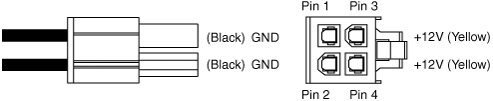
As you can see, using +12V to power the chip results in only 5.4A of draw, or 6.8A assuming 80% efficiency on the part of the regulator. So, modifying the motherboard VRM circuit to use the +12V power feed would seem simple. Unfortunately, the ATX 2.03 specification has only a single +12V lead in the main power connector. The auxiliary connector has no +12V leads at all, so that is no help. Pulling up to 8A more through a single 18-gauge wire supplying +12V power to the motherboard is a recipe for a melted connector because the contacts in the main ATX connector are rated for only 6A using standard terminals. To augment the supply of +12V power to the motherboard, Intel created a new ATX12V power supply specification. This added a third power connector, called the +12V connector, specifically to supply additional +12V power to the board. The 4-pin +12V power connector is specified for all power supplies conforming to the ATX12V form factor and consists of a Molex Mini-Fit Jr. connector housing with female terminals. For reference, the connector is Molex part number 39-01-2040 and the terminals are part number 5556. This is the same style of connector as the ATX Main power connector, except with fewer pins. This connector has two +12V power pins, each rated for 8A total using standard terminals (or up to 11A each using HCS terminals), allowing for up to 16A or more of additional +12V current to the motherboard, for a total of 22A of +12V when combined with the 20-pin main connector. The 4-pin +12V connector is shown in Figure 19.25. Figure 19.25. A 4-pin +12V power connector. The pinout of the +12V power connector is shown in Table 19.11.
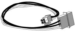
If you are replacing your motherboard with a new one that requires the +12V connection for the CPU voltage regulator, and yet your existing power supply doesn't have that connector, an easy solution is available. Merely convert one of the Peripheral power connectors to a +12V type. PC Power and Cooling has an adapter that can make any standard ATX power supply molex connector into one with a +12V connector. This connector works because the issue is not whether the power supply can generate the necessary +12Vthat has always been available via the Peripheral connectors. The +12V adapter shown in Figure 19.26 solves the connector problem quite nicely. Figure 19.26. +12V adapter from PC Power and Cooling. Using standard terminals, each pin in the +12V connector is rated to handle up to 8 amps of current, 11 amps with HCS terminals, or up to 12 amps with Plus HCS terminals. Even though it uses the same design and same terminals as the main power connector, the current rating per terminal is higher on this 4-pin connector than on the 20-pin main because there are fewer terminals overall. By counting the number of terminals for each voltage level, the power-handling capability of the connector can be calculated as shown in Table 19.12.
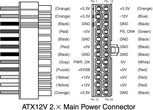
This means the total power handling capacity of this connector is 192 watts using standard terminals, which is available to and used only by the processor. Drawing more power than this maximum rating through the connector causes it to overheat, unless the HCS or Plus HCS terminals are used. Combining the 20-pin main plus the 4-pin +12V power connector results in a maximum power-delivery capability to the motherboard of 443 watts (using standard terminals). The important thing to note is that adding the +12V connector provides the capability to support power supplies of up to 500 watts or more without overloading and melting the connectors. The Reason for Multiple Motherboard Power ConnectorsOnly the 20-pin main power connector was included in the original ATX specification, and it was sufficient to power PC motherboards and processors in the mid-90s requiring 251 watts or less total power. However, by the late '90s, motherboard and processor power requirements had increased and in some systems the main power connector could no longer shoulder the load. Motherboards and processors that drew more than 251 total watts would potentially overheat the terminals and melt the connector housing, something I witnessed several times myself. Rather than change the design of the main connector and cause incompatibilities with motherboards that didn't need the additional power, Intel added the auxiliary power connector as a fix to the ATX 2.02 specification in 1998. The auxiliary connector was designed to deliver up to 58 watts of additional +3.3V and +5V power to power-hungry motherboards, which often need the additional power for CPU, memory, and AGP slot voltage regulators. Even though incorporating the additional auxiliary connector was basically a good idea, most motherboards I saw continued to use only the single main power connector, even if it might be overloaded. Although the auxiliary connector could provide extra +3.3V and +5V power, it did not provide any additional +12V power. The debut of the Pentium 4 processor in 2000 brought even greater power demands from the processor. CPUs run on very low voltages, which are normally provided via voltage regulators on the motherboard. These regulators take in the voltage provided by the power supply and convert it to that required by the processor. Power equals volts times amps. So, for the same power level, the more volts you provide the regulators, the fewer amps they require. Therefore, to reduce the overall current (amps) being delivered to the motherboard, a change was made to the CPU voltage regulators such that they would run on +12V power, instead of the +3.3V or +5V they had been previously using. This unfortunately created another power problem: Even when combining both the main and auxiliary power connectors, there was only a single +12V terminal supplying up to 6 amps of current to the motherboard. So, to provide additional +12V power and preserve compatibility with the main and auxiliary connectors that had already been defined, in early 2000 Intel added the +12V power connector to the ATX 2.1 specification. This new connector was designed specifically to deliver up to 192 watts of power for the high-output voltage regulators required by the Pentium 4 and newer processors. Power supplies with the +12V power connector were called ATX12V supplies, and a special ATX12V form factor specification was created just for the power supply. Because the +12V power connector was initially used on Pentium 4 motherboards, it became unofficially known as the P4 connector even though AMD processor-based motherboards began using it as well. By the end of 2001, most motherboards began requiring this connector and most power supplies being sold for PCs were the ATX12V type. Because the +12V power connector was designed specifically for the CPU, motherboards incorporating this connector would not run if power was not supplied to it. If you were installing a motherboard that used this connector and your power supply did not feature it as well, you could purchase an adapter that would convert one of the peripheral power connectors (normally used for disk drives) to a +12V power connector. If the power supply had the +12V connector but the motherboard did not, you could leave the +12V connector unplugged. Because the ATX12V standard includes the same main and auxiliary connectors as had previously been defined, an ATX12V power supply was fully backward compatible with ATX and could be used to replace a regular ATX type. If a motherboard did not require the extra +12V or auxiliary connectors, they could simply remain unplugged inside the case. As a consequence of changing the CPU voltage regulators on the motherboard to use +12V power, the load on the +3.3V and +5V rails was reduced such that the auxiliary connector was no longer necessary; consequently, many ATX12V supplies came without it. The auxiliary connector was officially removed from the ATX12V 2.0 specification in 2000. Some ATX12V power supplies still continue to include the auxiliary power connector, and of course you should be sure it is present if required by your motherboard. Because of the way the auxiliary and +12V connectors were added to the design, newer power supplies were almost always interchangeable with those in older systems. In fact, one of the greatest things about the ATX and ATX12V standards is that, aside from a few anomalies (such as certain proprietary Dell systems made in the late '90s with nonstandard power connector pinouts), most ATX12V power supplies will work in most PCs built from 1996 up to the present. Unfortunately, recent changes in motherboard and power supply form factors might mean that compatible power supply connections can't be taken for granted any longer. The recent changes in power supply form factors mostly relate to newer motherboards, processors, and even video cards requiring ever-increasing amounts of power. ATX12V 2.x 24-pin Main Power ConnectorStarting in June 2004, the new PCI Express bus first appeared on motherboards. PCI Express is a type of serial bus with standard slots having a single channel or lane of communications. These single-lane slots are called x1 slots and are designed for peripheral cards such as network cards, sound cards, and the like. PCI Express also includes a special higher-bandwidth slot with 16 lanes (called an x16 slot), which is especially designed for use by video cards. During development it was realized that PCI Express x16 video cards could draw more power than what was allowed by the existing 20-pin main and 6-pin auxiliary power supply connectors, especially when it came to +12V power. The problem was that the 20-pin main connector had only a single +12V pin and the new video cards required more +12V power than a single pin could safely deliver. The +12V connector that had already been added was specifically for the CPU and was unavailable to other devices. Rather than add another supplemental or auxiliary connector as it had done before, Intel eventually decided that it was finally time to upgrade the main power connector to supply more power. The result was officially called ATX12V 2.0 and was released in February 2003. ATX12V 2.0 included two major changes from the previous ATX12V 1.x specifications. This included a new 24-pin main power connector and the elimination of the 6-pin auxiliary power connector. The new 24-pin main power connector included 4 more pins supplying additional +3.3V, +5V, and +12V power plus a ground. The inclusion of these extra pins not only satisfied the power requirements for PCI Express video cards drawing up to 75 watts, but also made the older 6-pin auxiliary connector unnecessary. The pinout of the new 24-pin main power connector started to be implemented in motherboards in mid-2004 (see Figure 19.27). Figure 19.27. ATX12V 2.x 24-pin main power connector. When looking at this image, it's important to keep in mind that pin 13 might have a second orange or brown wire for +3.3V sense feedback, used by the power supply to monitor 3.3V regulation. Also, pin 20 might be N/C (no connection) because 5V was removed from the ATX12V 2.01 and later specifications. Supplies with no connection at pin 20 should not be used with older motherboards that incorporate ISA Bus slots. It is interesting to note that the 24-pin connector is not really that new; it first appeared in the Server System Infrastructure (SSI) Entry Power Supply (EPS) specification released in 1998. SSI (www.ssiforum.org) is an initiative designed to create standard interfaces for server components, including power supplies. The 24-pin main power connector was first created for servers because, at the time, only servers needed the additional power. Today's PCs draw the same power levels as servers did years ago, so rather than reinvent an incompatible connector, the ATX12V 2.0 standard merely incorporated the 24-pin connector already specified in the SSI EPS standard. Compared to the previous 20-pin design, the 24-pin main power connector includes additional +3.3V, +5V, and +12V terminals allowing a substantially greater amount of power to be delivered to the motherboard. Each terminal in the main power connector is rated to handle up to 6 amps of current. By counting the number of terminals for each voltage level, the power-handling capability of the connector can be calculated as shown in Table 19.13.
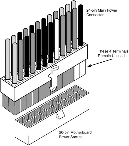
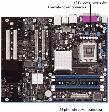
This means the total power-handling capacity of this connector is 373 watts using standard terminals or 560 watts using HCS terminals, which is substantially higher than the 251 watts available in the previous 20-pin connector. Combining the 24-pin main and the 4-pin +12V power connector results in up to 565 watts (standard terminals) or 824 watts (using HCS terminals) total power available to the motherboard and processor! This is more than enough to support the highest-output power supplies on the market today, despite the fact that the power supply also has to supply power to the various disk drives in the system. Backward and Forward CompatibilityIf you have reached this point, I'm sure you have some questions. For example, what happens if you purchase a new power supply that has a 24-pin main power connector but your motherboard has only a 20-pin main power socket? Likewise, what if you purchase a new motherboard that has a 24-pin main power socket but your power supply has only a 20-pin main power connector? The answers to these questions are surprising to say the least. First, let me say that there are adapters that can convert a 24-pin connector to a 20-pin type, and the other way around, but surprisingly these adapters are not usually necessary, or even desirable. The plain truth is that compatibility has been engineered into the connectors, power supplies, and motherboards from the start. If you look at the 24-pin main power connector diagram and compare it to the previous 20-pin design, you'll see that the extra 4 pins are all placed on one end of the connector and all the other pins are defined the same as they were previously. The design of these connectors is such that it allows an interesting bit of backward compatibility. The result is that you can plug a 24-pin main connector directly into a motherboard that has a 20-pin socket (and vice versa), without using an adapter! The trick is to position the connector such that the 4 extra pins are empty. Depending on the latch design, the latch on the side might not engage, but the connector will otherwise plug in and operate properly. Figure 19.28 shows how you would connect a new power supply with a 24-pin connector to a motherboard that has only a 20-pin socket. The terminals on the 24-pin connector that are highlighted in gray would plug directly into the 20-pin socket, while the white highlighted terminals would remain free and unconnected. Figure 19.28. Connecting a 24-pin main power connector to a 20-pin motherboard socket. Logically this works because the first 20 pins of the 24-pin connector that match the 20-pin motherboard socket contain the correct signals in the correct positions. The only problem that might arise is if there were some component on the motherboard directly adjacent to the end of the 20-pin power socket that would physically interfere with the four extra unused terminals on the 24-pin connector. What about the opposite condition, in which you have a new motherboard with a 24-pin socket but your power supply has only a 20-pin connector? In this case, four terminals at the end of the motherboard socket are not connected. This also works because the 20-pin portion of both the connector and socket are the same. But this example raises another question: Will the motherboard operate properly without the extra power pins? Because the extra signals are merely additional voltage pins that are already present in the remaining part of the connector, the answer should be yes, but if the motherboard draws a lot of power, it can overload the remaining pins. After all, preventing overloads is the reason the extra pins were added in the first place. Fortunately, even that problem has been solved. All the motherboards I've seen that use a 24-pin main power connector also have an additional peripheral (that is, disk drive) power connector onboard designed to provide the extra power that would be missing if you connected a 20-pin main power connector from your power supply. The documentation for the motherboard refers to this as an alternate power connector. Figure 19.29 shows an Intel D925XBC motherboard, which features 24-pin main, 4-pin +12V, and 4-pin alternate power connectors. Figure 19.29. Intel D925XBC motherboard power connectors. Regardless of whether you connect a 20- or 24-pin connector, the +12V power connector is always required because it provides power to the CPU. If you also plug a 24-pin main power connector into the 24-pin socket on the motherboard, the alternate power connection is unnecessary. However, you can plug a 20-pin main power connector into the 24-pin main power socket on the motherboard and then simply select a spare peripheral (disk drive) power connector from the power supply and plug it into the alternate power connector. Most power supplies have several extra peripheral power connectors for supporting additional drives. Using a 20-pin main and the alternate power connector satisfies the power requirements for the motherboard and any PCI Express x16 video cards, which can then draw up to 75 watts. As a side note, you should be careful when plugging in the mismatched connectors so that they are offset properly. The main, +12V, and PCI Express graphics connectors are Molex Mini-Fit Jr.type connectors that are keyed by virtue of a series of differently shaped plastic protrusions used around the terminals, which fit similarly shaped holes in the mating connectors. This keying is designed to prevent backward or improper off-center insertion, but I have found two problems with the keying that should be noted. One is that some alternate low-quality connector brands are built to looser tolerances than the original high-quality Molex versions, and the sloppier fit of the low-quality versions sometimes allows improper insertion. The other problem is that, with sufficient force, the keying on even the high-quality versions can be overcome. Because plugging a 20-pin connector into a 24-pin socketor a 24-pin connector into a 20-pin socketis designed to work even though they don't fully match up, you need to make sure you have the offsets correct or you risk damaging the board when you power it up. Dell Proprietary (Nonstandard) ATX DesignIf you currently own a desktop system made between 1996 and 2000 from Dell, you will definitely want to pay attention to this section. A potential booby trap is waiting to nail the unsuspecting owners of these systems who decide to upgrade either the motherboard or power supply. This hidden trap can cause the destruction of the motherboard, power supply, or both! Okay, now that I have your attention, read on.... As those of you who have attended my seminars or read previous editions of this book will know, I have long been a promoter of industry-standard components and wouldn't think of purchasing a desktop PC that didn't have what I consider an industry-standard form factor motherboard, power supply, and chassis (ATX, for example). I've been down the proprietary road before with systems from Packard Bell, Compaq, IBM, and other companies that used custom, unique, or proprietary components. For example, during a momentary lapse of reason in the early '90s, I purchased a Packard Bell system. I quickly outgrew the capabilities of the system, so I thought I'd upgrade it with a new motherboard and a faster processor. It was then that I discovered, to my horror, that LPX systems were not an interchangeable standard. Because of riser card differences, virtually no interchangeability of motherboards, riser cards, chassis, and power supplies existed. I had what I now refer to as a "disposable PC"the kind you can't upgrade and have to throw away instead. Suddenly, the money I thought I had saved when initially purchasing the system paled in comparison to what I'd now have to spend to completely replace it. Lesson learned. After several upgrade and repair experiences like that, I decided never again would I be trapped by systems using proprietary or nonstandard components. By purchasing only systems built with industry-standard parts, I could easily and inexpensively upgrade, maintain, or repair the systems for many years into the future. I have been preaching the gospel of industry-standard components in my seminars and in this book ever since. Of course, building your own system from scratch is one way to avoid proprietary components, but often that route is more costly in both time and money than purchasing a prebuilt system. And what systems should I recommend for people who want an inexpensive prebuilt system but one that uses industry-standard parts so it can be inexpensively upgraded and repaired later? Although many system vendors and assemblers exist, I've settled on companies such as Gateway, MPC (formerly MicronPC), and Dell. In fact, those are really the three largest system vendors that deal direct, and they mostly sell systems that use industry-standard ATX form factor components in all their main desktop system product lines. Or so I thought. It seems that when Dell converted to the ATX motherboard form factor in mid-1996, it unfortunately defected from the newly released standard and began using specially modified Intel-supplied ATX motherboards with custom-wired power connectors. Inevitably, it also had custom power supplies made that duplicated the nonstandard pinout of the motherboard power connectors. An even bigger crime than simply using nonstandard power connectors is that only the pinout is nonstandard; the connectors look like and are keyed the same as is dictated by true ATX. Therefore, nothing prevents you from plugging the Dell nonstandard power supply into a new industry-standard ATX motherboard you installed in your Dell case as an upgrade, or even plugging a new upgraded industry-standard ATX power supply into your existing Dell motherboard. But mixing either a new ATX board with the Dell supply or a new ATX supply with the existing Dell board is a recipe for silicon toast. How do you like your fried chips: medium or well-done? Frankly, I'm amazed I haven't heard more about this because Dell has climbed to the lead in worldwide PC sales. In any case, I figure by getting this information out I can save thousands of innocent motherboards and power supplies from instant death upon installation. If you've already fallen victim to this nasty circumstance, believe me, I feel your pain. I discovered this the hard way as wellby frying parts. At first, I thought the upgraded power supply I installed in one of my Dell systems was bad, especially considering the dramatic way it smoked when I turned on the system: I actually saw fire through the vents! Good thing I decided to check the color codes on the connectors and verify the pinout on another Dell system by using a voltmeter before I installed and fried a second supply. I was lucky in that the smoked supply didn't take the motherboard with it; I can only surmise that the supply fried so quickly it sacrificed itself and saved the motherboard. You might not be so lucky, and in most cases I'd expect you'd fry the board and supply together. Call me a fool, but I didn't think I'd have to check the color-coding or get out my voltmeter to verify the Dell "pseudo-ATX" power connector pinouts before I installed a new ATX supply or motherboard. You'll also find that motherboard and power supply manufacturers don't like to replace these items under warranty when they are fried in this manner due to nonstandard connector wiring. Dell's official explanation for its lack of conformance to the ATX standard was, "In the mid-90s the industry moved to a higher use of 3.3V motherboard components. Dell engineers designed a connector that supported the increased use of 3.3V current which differed from the industry proposed designs that we deemed less than robust." Unfortunately, this explanation doesn't hold much water because the standard ATX connector incorporated three 3.3V pins, allowing for up to 18A of current and the addition of the Auxiliary Connector added two more pins with 10A of additional current. Dell's pseudo-ATX design had only three 3.3V pins in the Auxiliary Connector, which could supply only up to 15A to the board. You can see that even the main ATX Connector alone had more 3.3V current than Dell's design using two connectors! Because its technical explanation fails to address the issue, the only other reason I can imagine it did this is to lock people into purchasing replacement motherboards or power supplies from Dell. What makes this worse is that Dell uses virtually all Intel-manufactured boards in its systems. One system I have uses an Intel D815EEA motherboard, which is the same board used by many of the other major system builders, including Gateway and Micron. It's the same, except for the power connectors, that is. The difference is that Dell has Intel custom make the boards for Dell with the nonstandard connectors. Everybody else gets virtually the same Intel boards, but with industry-standard connectors. Tables 19.14 and 19.15 show the nonstandard Dell main and auxiliary power supply connections. This nonstandard wiring is used on Dell's pseudo-ATX systems.
At first I thought that if all Dell did was switch some of the terminals around, I could use a terminal pick to remove the terminals from the connectors (with the wires attached) and merely reinsert them into the proper connector positions, enabling me to use the Dell power supply with an upgraded ATX motherboard in the future. Unfortunately, if you study the Dell main and auxiliary connector pinouts I've listed here and compare them to the industry-standard ATX pinouts listed earlier, you'll see that not only are the voltage and signal positions changed, but the number of terminals carrying specific voltages and grounds has changed as well. You could modify a Dell supply to work with a standard ATX board or modify a standard ATX supply to work with a Dell board, but you'd have to do some cutting and splicing in addition to swapping some terminals around. Usually, it isn't worth the time and effort. If you do decide to upgrade the motherboard in any Dell system purchased between 1996 and 2000, a simple solution is availablejust be sure you replace both the motherboard and power supply with industry-standard ATX components at the same time. That way nothing gets fried, and you'll be back to having a true industry-standard ATX system. If you want to replace just the Dell motherboard, you're out of luck unless you get your replacement board from Dell. On the other hand, if you want to replace just the power supply, you do have one alternative. PC Power and Cooling now makes several high-performance replacement power supplies with the modified Dell wiring. The internals are identical to its industry-standard, high-performance ATX suppliesonly the number and arrangement of wires have changed. Fortunately, starting in 2000, Dell switched to using industry-standard ATX power connections in its Dimension 4300, 4400, 8200, and newer systems. That means barring any other unforeseen glitches, these systems should be more easily upgradeable by just replacing either the power supply or the motherboard alone. Unfortunately, some of the newer Dell XPS systems use power supplies with proprietary mechanical form factors, which prevents you from installing an industry-standard replacement supply in the future. The bottom line is that, no matter which system you purchase, I recommend you check that it uses a power supply with an industry-standard form factor, both in regards to the electrical connectors and the physical shape. | |||||||||||||||||||||||||||||||||||||||||||||||||||||||||||||||||||||||||||||||||||||||||||||||||||||||||||||||||||||||||||||||||||||||||||||||||||||||||||||||||||||||||||||||||||||||||||||||||||||||||||||||||||||||||||||||||||||||||||||||||||||||||||||||||||||||||||||||||||||||||||||||||||||||||||||||||||||||||||||||||||||||||||||||||||||||||||||||||||||||||||||||||||||||||||||||||||||||||||||||||||||||||||||||||||||||||||||||
EAN: 2147483647
Pages: 283