Additional Power Connectors
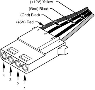
| Besides the motherboard power connectors, all power supplies include a variety of additional power connectors, mainly used for internally mounted drives but usable by other components as well. Most of these connectors are industry-standard types required by the various power supply form factor specifications. The following sections discuss the various types of additional device power connectors you're likely to find in your PC. Peripheral Power ConnectorsPerhaps the most common additional power connector seen on power supplies is the peripheral power connector, also called the disk drive power connector. What we know as the peripheral power connector was originally created by AMP as part of the commercial MATE-N-LOK series. To determine the location of pin 1, carefully look at the connector. It is usually embossed in the plastic connector body; however, it is often tiny and difficult to read. Fortunately, these connectors are keyed and therefore difficult to insert incorrectly. Figure 19.30 shows the keying with respect to pin numbers on the larger drive power connector. Figure 19.30. A peripheral power connector. This is the one connector type that has been on all PC power supplies from the original IBM PC to the latest systems built today. It is most commonly known as a disk drive connector, but it is also used in some systems to provide additional power to the motherboard, video card, cooling fans, or just about anything that can use +5V or +12V power. A peripheral power connector is a 4-pin connector with round terminals spaced 0.200" apart, rated to carry up to 11 amps per pin. Because there is one +12V pin and one +5V pin (the other two are grounds), the maximum power-handling capability of the peripheral connector is 187 watts. The plug is 0.830" wide, making it suitable for larger drives and devices. Table 19.16 shows the peripheral power connector pinout and wire colors.
Floppy Power ConnectorsWhen 3 1/2" floppy drives were first being integrated into PCs in the mid-1980s, it was clear that a smaller power connector was necessary. The answer came in what is now known as the floppy power connector, which was created by AMP as part of the EI (economy interconnection) series. These connectors are now used on all types of smaller drives and devices and feature the same +12V, +5V, and ground pins as the larger peripheral power connector. The floppy power connector has 4 pins spaced 2.5mm (0.098") apart, which makes the entire connector about half the overall width as the larger peripheral power connector. The pins are rated for only 2 amps each, giving a maximum power-handling capability of 34 watts. Table 19.17 shows the pinouts for the smaller floppy drive power connector.
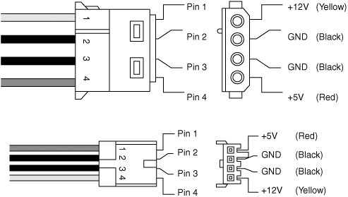
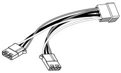
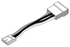
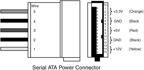
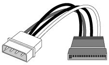
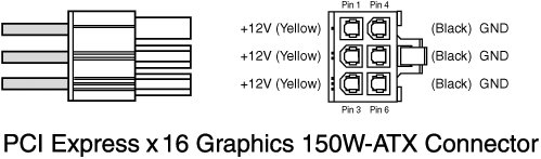
The peripheral and floppy power connectors are universal with regard to pin configuration and even wire color. Figure 19.31 shows the peripheral and floppy power connectors. Figure 19.31. Peripheral and floppy power connectors. The pin numbering and voltage designations are reversed on the floppy power connector. Be careful if you are making or using an adapter cable from one type of connector to another. Reversing the red and yellow wires will fry the drive or device you plug in to. Early power supplies featured only two peripheral power connectors, whereas later power supplies featured four or more of the larger peripheral (disk drive) connectors and one or two of the smaller floppy power connectors. Depending on their power ratings and intended uses, some supplies have as many as eight or more peripheral and/or floppy power connectors. If you are adding drives and need additional power connectors, Y splitter cables (see Figure 19.32) as well as peripheral-to-floppy power connector adapters (see Figure 19.33) are available from many electronics supply houses (including RadioShack). These cables can adapt a single power connector to service two drives or enable you to convert the large peripheral power connector to a smaller floppy drive power connector. If you are using several Y-adapters, be sure that your total power supply output is capable of supplying the additional power and that you don't draw more power than a single connector can handle. Figure 19.32. A common Y-adapter power cable. Figure 19.33. A peripheral-to-floppy power adapter cable. Serial ATA Power ConnectorsIf you want to add Serial ATA drives to an existing system, you will need a newer power supply that includes a Serial ATA (SATA) power connector. The SATA power connector is a special 15-pin connector fed by only five wires, meaning 3 pins are connected directly to each wire. The overall width is about the same as the peripheral power connector, but the SATA connector is significantly thinner. All the most recent power supply form factor specifications include SATA power connectors as mandatory for systems supporting SATA drives. Figure 19.34 shows a Serial ATA power connector. Figure 19.34. A Serial ATA power connector. In the SATA power connector, each wire is connected to three terminal pins and the wire numbering is not in sync with the terminal numbering, which can be confusing. If your power supply does not feature SATA power connectors, you can use an adapter to convert a standard peripheral power connector to a SATA power connector. However, such adapters do not include the +3.3V power. Fortunately, though, this is not a problem for most uses because most drives do not require +3.3V and use only +12V and +5V instead. Figure 19.35 shows a peripheral-to-SATA power connector adapter. Figure 19.35. A peripheral-to-SATA power adapter. PCI Express x16 Graphics Power Connectors (SLI)Although the ATX12V 2.x specification includes a new 24-pin main power connector with more power for devices such as video cards, the design was intended to power a video card drawing up to 75 watts maximum. There are already some video cards on the market drawing more power than that; for example, NVIDIA's GeForce 6800 Ultra draws 110 watts and future cards might draw even more power. Greater than 75 watts cannot be provided via the motherboard directly, so the PCI-SIG (Special Interest Group) developed a standard for supplying at least 150 watts of power directly to the video card from the power supply via an additional graphics power connector. This will likely be included in future ATX12V power supply standards as well. The PCI Express x16 Graphics Power specification consists of a 6-pin Molex Mini-Fit Jr. connector housing with female terminals that is used to provide power directly to the video card. For reference, the connector is Molex part number 39-01-2060 and the terminals are part number 5556 (standard terminals). This is the same style of connector as the main and +12V power connectors. The pinout of the connector is shown in Figure 19.36. Figure 19.36. PCI Express x16 Graphics 150W power connector. Pin 2 is technically listed as "not connected" in the specification. Most graphics cards don't use it, but most power supplies do seem to include +12V there. Each pin in the PCI Express graphics power connector is rated to handle up to 8 amps of current using standard terminals or 11 amps using HCS terminals. By counting the number of terminals for each voltage level, the power-handling capability of the connector can be calculated (see Table 19.18).
Even though the specification calls for a delivery capability of only 150 watts, the total power-handling capacity of this connector is actually 192 watts using standard terminals, or 264 watts using HCS terminals. This should be more than enough for even the most power-hungry video cards in the future. These connectors are often called SLI connectors because they are used by high-end PCI Express x16 boards with SLI capabilities. SLI is NVIDIA's method of using two video cards in unison, with each one drawing half of the screen for twice the performance. Each card can draw upwards of 150 watts, so most power supplies that are rated as SLI-ready include two of the 6-pin PCI Express x16 150W graphics power connectors. Using two video cards drawing 110 watts each means that, even if you have a 500-watt power supply, you will need only 280 watts of power to run the motherboard and all the disk drives. Systems using dual SLI video cards require the highest-output supplies available, and some of the current ones are capable of putting out up to 1,000 watts (1 kilowatt) or more. Note NVIDIA has trademarked the term SLI as meaning scalable link interface, but its primary competitorATalso uses similar dual-graphics card technology called CrossFire to achieve similar performance improvements. If your existing power supply doesn't feature a PCI Express x16 Graphics power connector, you can use a Y-adapter to convert two peripheral power connectors into a single 6-pin PCI Express x16 power connector. | |||||||||||||||||||||||||||||||||||||||||||||||||||||||||||||||||
EAN: 2147483647
Pages: 283