7.11 Serial Digital Video Interfaces
| | ||
| | ||
| | ||
7.11 Serial Digital Video Interfaces
The serial interfaces described here have a great deal of commonality . Any differences will be noted subsequently. All of them allow up to ten-bit samples to be communicated serially 10 . If there are only eight bits in the input samples, the missing bits are forced to zero for transmission except for the all-ones condition during TRS which will be forced to ten ones. The interfaces are transparent to ancillary data in the parallel domain, including conveyance of AES/EBU digital audio channels.
Serial transmission uses concepts that were introduced in Chapter 3. At the high bit rates of digital video, the cable is a true transmission line in which a significant number of bits are actually in the cable at any one time, having been sent but not yet received. Under these conditions cable loss is significant. These interfaces operate with cable losses up to 30 dB. The losses increase with frequency and so the bit rate in use and the grade of cable employed both affect the maximum distance the signal will safely travel. Figure 7.24 gives some examples of cable lengths that can be used in SD. In HD there is only one bit rate. Using Belden 1649A or equivalent, a distance of 140 m can be achieved.
| System | Clock | Fundamental | Crash Knee length | Practical length |
|---|---|---|---|---|
| NTSC Composite | 143 MHz | 71.5 MHz | 400 m | 320 m |
| PAL Composite | 177 MHz | 88.5 MHz | 360 m | 290 m |
| Component 601 | 270 MHz | 135 MHz | 290 m | 230 m |
| Component 16:9 | 360 MHz | 180 MHz | 210 m | 170 m |
| CABLE: BICC TM3205, PSF1/2, BELDEN 8281 or any cable with a loss of 8.7 dB/100 m at 100 MHz | ||||
Figure 7.24: Suggested maximum cable lengths as a function of cable type and data rate to give a loss of no more than 30 dB. It is unwise to exceed these lengths due to the 'crash knee' characteristic of SDI.
Serial transmission uses a waveform that is symmetrical about ground and has an initial amplitude of 800 mV pk-pk across a 75 ohm load. This signal can be fed down 75 ohm coaxial cable having BNC connectors. Serial interfaces are restricted to point-to-point links. Unlike analog video practice, serial digital receivers contain correct termination that is permanently present and passive loop-through is not possible. In permanent installations, no attempt should be made to drive more than one load using T-pieces as this will result in signal reflections that seriously compromise the data integrity. On the test bench with very short cables, however, systems with all manner of compromises may still function.
The range of waveforms that can be received without gross distortion is quite small and raw data produce waveforms outside this range. The solution is the use of scrambling, or pseudo-random coding. The serial interfaces use convolutional scrambling as was described in Chapter 3. This is simpler to implement in a cable installation because no separate synchronizing of the randomizing is needed. The scrambling process at the transmitter spreads the signal spectrum and makes that spectrum reasonably constant and independent of the picture content. It is possible to assess the degree of equalization necessary by comparing the energy in a low-frequency band with that in higher frequencies. The greater the disparity, the more equalization is needed. Thus fully automatic cable equalization at the receiver is easily achieved.
The essential parts of a serial link are shown in Figure 7.25. Parallel data having a word length of up to ten bits forms the input. These are fed to a ten-bit shift register which is clocked at ten times the input word rate: 1.485GHz, 360MHz, 270MHz or 40 — F sc . The serial data emerge from the shift register LSB first and are then passed through the scrambler, in which a given bit is converted to the exclusive-OR of itself and two bits that are five and nine clocks ahead. This is followed by another stage, which converts channel ones into transitions. The transition encoder ensures that the signal is polarity independent. The resulting logic level signal is converted to a 75 ohm source impedance signal at the cable driver.
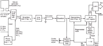
Figure 7.25: Major components of an SDI link. See text for details.
The receiver must regenerate a bit clock at 1.485MHz, 360MHz, 270MHz or 40 — F sc from the input signal, and this clock drives the input sampler and slicer which converts the cable waveform back to serial binary. The local bit clock also drives a circuit that simply reverses the scrambling at the transmitter. The first stage returns transitions to ones. The second stage is a mirror image of the encoder and reverses the exclusive-OR calculation to output the original data. Such descrambling results in error extension, but this is not a practical problem since link error rates are practically zero.
As transmission is serial, it is necessary to obtain word synchronization, so that correct deserialization can take place. The TRS patterns are used for this purpose. The all-ones and all-zeros bit patterns form a unique 30-bit sequence which is detected in the receiver's shift register. The transition from all ones to all zeros is on a word boundary and from that point on the deserializer simply divides by ten to find the word boundaries in the transmission.
7.11.1 Standard Definition Serial Digital Interface (SDI)
This interface supports 525/59.94 2:1 and 625/50 2:1 scanning standards in component and composite. The component interfaces use a common bit rate of 270 MHz for 4:3 pictures with an option of 360 MHz for 16:9. In component, the TRS codes are already present in the parallel domain and SDI does no more than serialize the parallel signal protocol unchanged.
Composite digital samples at four times the subcarrier frequency and so the bit rate is different between the PAL and NTSC variants. The composite parallel interface signal is not a multiplex and also carries digitized analog syncs. Consequently there is no need for TRS codes. For serial transmission it is necessary to insert TRS at the serializer and subsequently to strip it out at the serial-to-parallel convertor. The TRS-ID is inserted during blanking, and the serial receiver can detect the patterns it contains. Composite TRS-ID is different to the one used in component signals and consists of five words inserted just after the leading edge of analog video sync. Figure 7.26(a) shows the location of TRS-ID at samples 967971 in PAL and (b) shows the location at samples 790794 in NTSC.
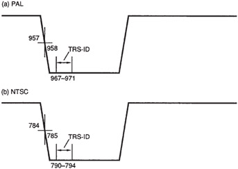
Figure 7.26: In composite digital it is necessary to insert a sync pattern during analog sync tip to ensure correct deserialization. The location of TRS-ID is shown at (a) for PAL and at (b) for NTSC.
Out of the five words in TRS-ID, the first four are for synchronizing, and consist of a single word of all ones, followed by three words of all zeros. Note that the composite TRS contains an extra word of zeros compared with the component TRS and this could be used for signal identification in multi-standard devices. The fifth word is for identification, and carries the line and field numbering information shown in Figure 7.27. The field numbering is colour-framing information useful for editing. In PAL the field numbering will go from zero to seven, whereas in NTSC it will only reach three.
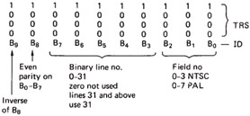
Figure 7.27: The contents of the TRS-ID pattern which is added to the transmission during the horizontal sync pulse just after the leading edge. The field number conveys the composite colour framing field count, and the line number carries a restricted line count intended to give vertical positioning information during the vertical interval. This count saturates at 31 for lines of that number and above.
On detection of the synchronizing symbols, a divide-by-ten circuit is reset, and the output of this will clock words out of the shift register at the correct times. This circuit will also provide the output word clock.
7.11.2 SDTI
SDI is closely specified and is only suitable for transmitting 2:1 interlaced 4:2:2 digital video in 525/60 or 625/50 systems. Since the development of SDI, it has become possible economically to compress digital video and the SDI standard cannot handle this. SDTI (serial data transport interface) is designed to overcome that problem by converting SDI into an interface that can carry a variety of data types whilst retaining compatibility with existing SDI router infrastructures .
SDTI sources produce a signal which is electrically identical to an SDI signal and which has the same timing structure. However, the digital active line of SDI becomes a data packet or item in SDTI. Figure 7.28 shows how SDTI fits into the existing SDI timing. Between EAV and SAV (horizontal blanking in SDI) an ancillary data block is incorporated. The structure of this meets the SDI standard, and the data within describes the contents of the following digital active line.
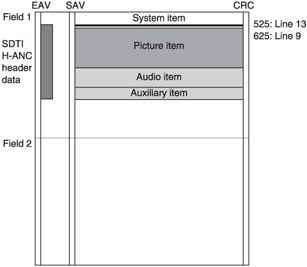
Figure 7.28: SDTI is a variation of SDI which allows transmission of generic data. This can include compressed video and non-real -time transfer.
The data capacity of SDTI is about 200 Mbits/s because some of the 270 Mbits/s are lost due to the retention of the SDI timing structure. Each digital active line finishes with a CRCC (cyclic redundancy check character) to check for correct transmission.
SDTI raises a number of opportunities, including the transmission of compressed data at faster than real time. If a video signal is compressed at 4:1, then one quarter as much data would result. If sent in real time the bandwidth required would be one quarter of that needed by uncompressed video. However, if the same bandwidth is available, the compressed data could be sent in one quarter of the usual time. This is particularly advantageous for data transfer between compressed camcorders and non-linear editing workstations. Alternatively, four different 50 Mbit/s signals could be conveyed simultaneously .
Thus an SDTI transmitter takes the form of a multiplexer which assembles packets for transmission from input buffers. The transmitted data can be encoded according to MPEG, MotionJPEG, Digital Betacam or DVC formats and all that is necessary is that compatible devices exist at each end of the interface. In this case the data are transferred with bit accuracy and so there is no generation loss associated with the transfer. If the source and destination are different, that is, having different formats or, in MPEG, different group structures, then a conversion process with attendant generation loss would be needed.
7.11.3 ASI
The asynchronous serial interface is designed to allow MPEG transport streams to be transmitted over standard SDI cabling and routers. ASI offers higher performance than SDTI because it does not adhere to the SDI timing structure. Transport stream data do not have the same statistics as PCM video and so the scrambling technique of SDI cannot be used. Instead ASI uses an 8/10 group code (see section 3.8) to eliminate DC components and ensure adequate clock content.
SDI equipment is designed to run at a closely defined bit rate of 270 Mbits/s and has phase-locked loops in receiving and repeating devices which are intended to remove jitter. These will lose lock if the channel bit rate changes. Transport streams are fundamentally variable in bit rate and to retain compatibility with SDI routing equipment ASI uses stuffing bits to keep the transmitted bit rate constant.
The use of an 8/10 code means that although the channel bit rate is 270 Mbits/s, the data bit rate is only 80% of that, that is, 216 Mbits/s. A small amount of this is lost to overheads.
7.11.4 High Definition Serial Digital Interface (HD-SDI)
The SD serial interface runs at a variety of bit rates according to the television standard being sent. In contrast the HD serial interface 11 runs at only one bit rate, 1.485Gbits/s, although it is possible to reduce this by 0.1% so that it can lock to traditional 59.94Hz equipment. At this high bit rate, variable speed causes too many difficulties and it is easier to accommodate a reduced data rate by sending more blanking or ancillary data so that the transmitted bit rate stays the same. A receiver can work out which format is being sent by counting the number of blanking periods between the active lines.
Apart from the bit rate, the HD serial interface has as much in common with the SDI standard as possible. Although the impedance, signal level and channel coding are the same, the HD serial interface has a number of detail differences in the protocol.
The parallel HD interface above has two channels, one for luma and one for multiplexed colour difference data. Each of these has a symbol rate of 74.25 MHz and has its own TRS-ID structure. Essentially the HD serial interface is transparent to this data as it simply multiplexes between the two channels at symbol rate. As far as the active line is concerned , the result is the same as for SD: a sequence of C b , Y, C r , Y , etc. However, in HD the TRS-IDs of the two channels are also multiplexed. A further difference is that the HD interface has a line number and a CRC for each active line inserted immediately after EAV. Figure 7.29(a) shows the EAV and SAV structure of each channel, with the line count and CRC, whereas (b) shows the resultant multiplex.
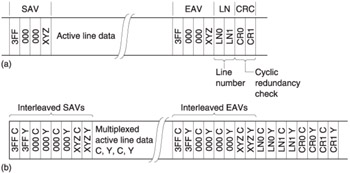
Figure 7.29: The HD parallel data are in two channels, each having their own TRS, shown at (a). The EAV is extended by line number and CRC. (b) When the two channels are nultiplexed, the TRS codes are interleaved as shown.
| | ||
| | ||
| | ||
EAN: 2147483647
Pages: 120