MPLS Concepts
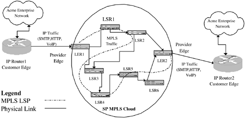
| MPLS is a forwarding technology. Its purpose is to receive an incoming traffic type (layer 2 or 3) at the network edge, encapsulate it, and then transmit it through an MPLS core (or cloud). At the exit from the cloud, another edge device removes the MPLS header and forwards the traffic towards its destination. An example is illustrated in Figure 2-7, where the incoming IP traffic from the Acme enterprise network consists of a mixture of SMTP (email), HTTP (Web), and VoIP. This traffic is routed from IP Router 1 on the customer premises. The traffic then lands at the provider edge (LER1), where an IP header lookup is carried out on each packet prior to pushing an MPLS-encapsulated packet into the LSP (label switched path ; this process is described in a little more detail below). The MPLS cloud in Figure 2-7 consists of many routers; a big network might have hundreds (or even thousands) of such routers distributed over a wide geographic area. The MPLS cloud routers in a real network would have many more edge connections than just the two IP routers shown. In other words, the SP network could have many thousands of such devices connected to it. Figure 2-7. An MPLS network joining enterprise branches. MPLS nodes are either edge or core devices. Edge routers are called label edge routers (LERs) and core routers are called label switching routers (LSRs). Edge routers (such as LER1 in Figure 2-7) sit at the boundary (or provider edge) of the network, facing the IP traffic stream on one side and the interior of the MPLS cloud on the other. Core routers, such as LSR1 in Figure 2-7, sit inside the MPLS cloud. Ingress LERs encapsulate IP traffic as MPLS packets and push these onto LSPs in the core of the MPLS cloud. We define LSPs more fully in the next section ”for the moment, just think of them as layer 3 virtual connections or pipes that carry traffic from edge to edge through the network. In Figure 2-7, IP Router 1 presents an IP traffic stream (SMTP, HTTP, VoIP) at an ingress interface of LER1. LER1 performs normal lookups on the IP headers of the incoming packets. From the destination IP address (or some other part of the IP header), LER1 can decide how best to forward the packets, and it has a number of choices. Taking the first IP packet that arrives, LER1 can:
In Figure 2-7, LER1 decides to take the last option in the above list, and the MPLS packet is transported via an LSP. The MPLS traffic is then pushed onto the LSP comprised of the ingress interfaces on the following nodes: LSR1-LSR2-LSR3-LSR4-LSR5-LSR6-LER2. This path is shown as a dashed line in Figure 2-7. An LSP has the following characteristics:
Some MPLS nodes can simultaneously function as ATM switches and MPLS nodes. ATM-based MPLS nodes have an important feature called ships-in-the-night (SIN). This allows both ATM and MPLS protocols to operate independently of one another on the same port (that is, MPLS is configured on the port, creating an MPLS interface). Not all MPLS nodes can simultaneously act as MPLS and ATM switches; for example, Juniper routers and Cisco 7000/12000 routers cannot. Some models of switches from Nortel, Lucent, and Marconi can. The provision of SIN is an effort to facilitate a gradual migration of networks from ATM to MPLS. Service providers can continue to deploy revenue producing, legacy services based on ATM while slowly introducing MPLS-based services (such as RFC 2547 VPNs). So, the nodes in Figure 2-7 can also create ATM virtual circuits alongside MPLS LSPs. These ATM circuits can then natively transport ATM cells . SIN conceptually splits a switch into a combination of an ATM and an MPLS device, like two mini-switches. It can result in a fragmented label space, and also there may be an effect on performance if a great deal of unlabeled IP traffic is in transit across the switch. The MPLS nodes can run traffic engineering-enabled routing protocols such as Open Shortest Path First (OSPF) and Intermediate System-Intermediate System (IS-IS). This allows the exchange of traffic engineering data, such as available (and used) link bandwidth. Definition of an LSPAs we've seen, an LSP is an automatically or manually configured ( optionally traffic-engineered with optional QoS) path through an MPLS network. An LSP originates on an LER, passes through zero or more LSRs, and terminates on another LER. The path taken by the LSP can be set by the operator or computed by the LER. Network resources, such as bandwidth, can be reserved along the path, or the LSP can offer a best-effort service. With reference to the MIBs examined in Chapter 8, an LSP is comprised of the following components on the originating LER:
Each LSR in the core then supports the LSP by providing the following components:
Finally, the terminating LER provides the endpoint for the LSP using the following components:
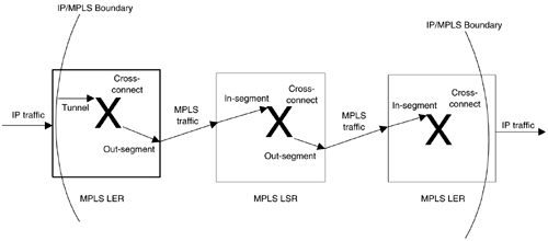
So, a notional network made up of two LERs and one LSR with an LSP spanning all three nodes might look like Figure 2-8. Figure 2-8. LSP components. Figure 2-8 illustrates the above components as well as another important concept: the IP/MPLS boundary. This boundary is the edge of the MPLS cloud; that is, on the IP side of the boundary there is only IP ”all MPLS labels have been stripped off. On the MPLS side of the boundary there can be both IP and MPLS. In other words, there is no reason why pure IP traffic cannot traverse an MPLS core. Why might this arise? One possibility is that a packet arrives with a destination IP address that is not served by any existing LSP. In this case, the packet can be routed hop by hop through the MPLS core. Packets arriving on the edge of the IP/MPLS boundary are subjected to a normal IP lookup, but if their destination address is served by an LSP, then they are MPLS-encapsulated and pushed into the appropriate tunnel (as illustrated in Figure 2-8). The encapsulated packets then pass through the segments and cross-connects of the LSP path, consuming any of the resources reserved on that path. One important part of LSP setup is the programming of the hardware. One of the major drivers of MPLS is that the MPLS management plane hides the platform-specific details. In this way, the platform-specific protocols impose the required labels, traffic engineering requirements, and QoS settings on the relevant interfaces across the network. The network operator employs the management interface to initiate this process. SNMP, in this context, is just another management interface, as is a CLI. LSPs are set up from edge to edge traversing the LSRs in the core. LSPs serve as a conduit for transporting MPLS traffic from the point of ingress at the edge to the point of egress on another edge. We will see the structure illustrated in Chapter 8. One final important point about MPLS is that it is not restricted to carrying just IP traffic. The traffic landing at LER1 can also be Ethernet, ATM, and TDM. Carrying legacy traffic is an important part of MPLS. |
EAN: 2147483647
Pages: 150

