Chapter 17: Local Area Networks
|
| < Day Day Up > |
|
During the1980s, PCs became ubiquitous in all organizations. Every executive started having his own PC for automation of individual activities. The need arose for sharing information within the organization—sending messages, sharing files and databases, and so forth. Whether the organization is located in one building or spread over a large campus, the need for networking the computers cannot be overemphasized. Today, we hardly find a computer, that is not networked. A local area network (LAN) interconnects computers over small distances up to about 10 kilometers. In this chapter, we will study the various configurations, technologies, protocols, and standards of LANs.
17.1 THE ETHERNET LAN
In 1978, Xerox Corporation, Intel Corporation, and Digital Equipment Corporation standardized Ethernet. This has become the most popular LAN standard. IEEE released a compatible standard, IEEE 802.3. A LAN is represented in Figure 17.1.
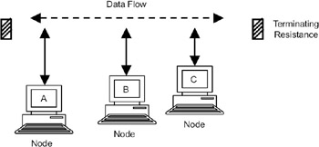
Figure 17.1: Ethernet LAN.
The Ethernet local area network developed by Xerox, Intel, and DEC in 1978 became the most popular LAN standard. IEEE released a compatible standard called IEEE 802.3.
The cable, called the Ether, is a coaxial cable of ½ inch diameter and up to 500 meters long. A resistor is added between the center wire and the shield at each end of the cable to avoid reflection of the electrical signal. The cable is connected to a transceiver (transmitter and receiver) whose job is to transmit the signals onto the Ether and also to sense the Ether for the presence of the signals. The transceiver is connected through a transceiver cable (also called attachment unit interface cable) to a network card (also known as a network adapter card). The network card is a PC add-on card that is plugged into the motherboard of the computer. The coaxial cable used in Ethernet LAN is shown in Figure 17.2.
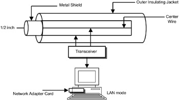
Figure 17.2: Coaxial cable used in an Ethernet LAN.
This architecture is known as bus architecture because all the nodes share the same communication channel. Ethernet operates at 10Mbps data rate. When a node has data to transmit, it divides the data into packets, and each packet is broadcast on the channel. Each node will receive the packet, and if the packet is meant for it (based on the destination address in the packet), the packet will be processed. All other nodes will discard the packet.
17.1.1 LAN Protocol Layers
The protocol architecture of a LAN is shown in Figure 17.3. Every node on the LAN will have hardware/ software corresponding to all these layers. The bottom two protocol layers are
-
Physical layer
-
Datalink layer, which is divided into
-
Medium access control (MAC) sublayer
-
Logical link control (LLC) sublayer
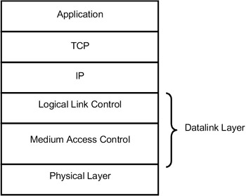
Figure 17.3: LAN protocol layers.
In LAN protocol architecture, the bottom two layers—physical layer and datalink layer—are defined. The datalink layer is divided into two sublayers: medium access control sublayer and logical link control sublayer.
Above the datalink layer, the TCP/IP protocol suite is run to provide various applications on, the LAN. The network card and the associated software in the PC provide the first two layers' functionality, and the TCP/IP stack is integrated with every desktop operating system (Windows, Unix/Linux, etc.). While studying LANs, we will focus only on these two layers. All the standards for LANs, which we will study in subsequent sections, will also address only these two layers.
Physical layer: This layer specifies the encoding/decoding of signals, preamble generation, and removal for synchronization and bit transmission and reception.
MAC sublayer: The MAC sublayer governs the access to the LAN's transmission medium. A special protocol is required because a number of nodes share the same medium. This protocol is known as the medium access control protocol. In Ethernet, the medium access protocol is carrier sense multiple access/ collision detection (CSMA/CD).
LLC sublayer: Above the MAC sublayer, the LLC layer runs. The data received from the higher layer (IP layer) is assembled into frames, and error detection and address fields are added at the transmitter and sent to the MAC layer. The MAC layer, when it gets a chance to send its data using CSMA/CD protocol, sends the frame via the physical layer. At the receiver, frames are disassembled, the address is recognized, and error detection is carried out. The LLC layer provides interface to the higher layers.
The MAC sublayer defines the protocol using which multiple nodes share the medium. In Ethernet, the MAC protocol is carrier sense multiple access/ collision detection (CSMA/CD).
17.1.2 CSMA/CD Protocol
In Ethernet LANs, all the nodes share the same medium (Ether). The protocol used to share the medium is known as carrier sense multiple access with collision detection (CSMA/CD).
When a node has to send a packet, it will broadcast it on the medium. All the nodes on the LAN will receive the packet and check the destination address in the packet. The node whose address matches the destination address in the packet will accept the packet. To ensure that more than one node does not broadcast its packet on the Ether, just before transmitting a packet, each node has to first monitor the Ether to determine if any signal is present; in other words, sense the carrier. However, there is still a problem—take the case of two nodes (A and C) on the LAN in Figure 17.1. If node A sent a packet, it takes finite time for the signal to reach node C. Meanwhile, node C will sense the carrier and find that there is no activity on the Ether, so it also will send a packet. These two packets will collide on the medium, resulting in garbling of data. To avoid these collisions, each node will wait for a random amount of time if a collision occurs. Binary exponential back-off policy is used to avoid collisions to the maximum possible extent—a node will wait for a random amount of time if there is a collision, twice that time if there is a second collision, thrice that time if there is third collision, and so on. This ensures that the probability of collisions is minimized. But a collisions cannot be eliminated altogether. That is why, even though on the Ethernet the data can be transmitted at the rate of 10Mbps, the effective data rate or throughput will be much lower.
| Note | When a collision of packets occurs on the medium, each node has to follow the binary exponential back-off policy wherein a node has to wait for a random amount of time if a collision occurs, twice that time if a collision occurs a second time, and so on. |
17.1.3 Ethernet Addresses
To identify each node (computer) attached to the Ethernet, each node is given a 48-bit address. This address is also known as the hardware address or physical address because the network card on the computer carries this address, which is given by the hardware manufacturer. Therefore, each computer is uniquely identified.
The Ethernet address can be of three types:
-
Unicast address
-
Broadcast address
-
Multicast address
When a node sends a packet with a unicast address, the packet is meant for only one node specified by that address. When a node sends a packet with a broadcast address (all ones), the packet is meant for all the nodes on the network. A set of nodes can be grouped together and given a multicast address. When a node sends a packet with a multicast address, the packet is meant for all the nodes in that group. Generally, network cards accept the unicast address and broadcast address. They can also be programmed to accept multicast addresses.
Each computer on an Ethernet LAN is identified by a 48-bit address. This address is contained in the network card on the computer.
| Note | Ethernet address can be of three types: unicast, broadcast, and multicast. Generally, network cards accept unicast addresses and broadcast addresses. They need to be specially programmed to accept multicast addresses. |
17.1.4 Ethernet Frame Format
The Ethernet frame format is shown in Figure 17.4.
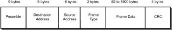
Figure 17.4: Ethernet frame format.
Preamble (8 bytes): The beginning of the frame.
Destination address (6 bytes): Destination address of the packet.
Source address (6 bytes): Source address of the packet.
Frame type (2 bytes): Type of the frame.
Frame data (variable): User data, which can vary from 64 bytes to 1500 bytes.
CRC (4 bytes): 32-bit CRC computed for each frame.
The maximum allowed size of an Ethernet frame is 1526 bytes, out of which 26 bytes are used for the header and the CRC. Hence, 1500 bytes is the maximum allowed user data in an Ethernet frame.
Hence, the maximum allowed size of an Ethernet frame is 1526 bytes. This is the frame format of Ethernet developed by Digital, Intel, and Xerox.
Above the LLC, the IP layer runs, and each node on the LAN is assigned an IP address. Above the IP layer, the TCP layer and other application layer protocols run to provide applications such as e-mail, file transfer, and so on.
Ethernet LANs have become widely popular. Initially, 10Mbps Ethernet LANs were used, and now 100Mbps Ethernet LANs are common.
|
| < Day Day Up > |
|
EAN: 2147483647
Pages: 313