Carrier Supporting Carrier (CsC)
| Carrier supporting carrier (CsC) was originally developed for MPLS VPN-enabled service providers to support other MPLS/VPN providers (hence its name). With the adoption of MPLS VPNs in large enterprises, CsC is a service that service providers could provide to large enterprises, too. Therefore, you can think about it as a "carrier supporting enterprise service." The enterprise must obtain a label transport service from a provider. In other words, the labels and label exchange for the enterprise should be transported somewhat transparently between enterprise sites by the service provider. Therefore, the enterprise WAN edge devices should act as though they are directly connected E-P devices. CsC allows such a transparent label transport without requiring the creation of tunnels. WAN extensibility techniques, other than CsC, require the overlay of a logical topology that is usually based on IP tunnels to provide logical direct connectivity between E-P or E-PE routers. A label transport service is an elegant solution because it does not require a static IP tunnel overlay and the labels can be "tunneled" natively by the service provider MPLS network label stacking mechanisms. Thus, the service provider can continue to provide the anyto-any connectivity from the IP VPN without added complexity. The service provider network ensures that the packet is forwarded to the correct enterprise network location based on the incoming label. The best part is that this process is relatively transparent to the enterprise. For the carrier to be able to carry the enterprise VNs, certain control-plane information must be exchanged between the enterprise and the provider and between the enterprise sites. As shown in Figure 7-10, the control plane has two added relationships:
Figure 7-10. CsC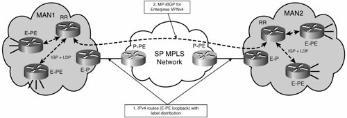 In terms of the configuration, the E-P routers facing the provider must be configured to label switch on the WAN interfaces. This configuration involves enabling MPLS globally (ip cef, mpls label protocol ldp) and enabling MPLS under the WAN interfaces (mpls ip). No VRFs have to be configured on the E-P routers. Note Alternatively, you could use eBGP to carry the necessary label information instead of having the label carried by LDP. This is alternative represents a different way of achieving CsC, one that does not require the WAN interfaces to participate in the LDP. For the purposes of our discussion, we focus on the LDP-based model. In addition, you must configure a routing protocol for the global routing table to learn and advertise the addresses of the different PEs and RRs. If you are using the same IGP as the enterprise uses internally, the configuration is as simple as including the subnet for the WAN interface in the IGP. For OSPF, this would be something along the lines of Example 7-1. Example 7-1. Using OSPF to Advertise E-PE and E-RR Addresses into the Provider
If using eBGP, you must configure eBGP peering between the E-P at the edge and P-PE routers and redistribute the enterprise IGP into the eBGP process and vice versa, as shown in Example 7-2. Example 7-2. Using eBGP to Advertise E-PE and E-RR Addresses into the Provider
Finally, the RRs on the different enterprise MPLS networks must MP-iBGP peer with each other. The peering must convey VPNv4 routes, and therefore the peering RRs must be activated under the VPNv4 address families so that the updates can carry the route targets, distinguishers, and label information as shown in Table 7-2.
Note We have shown a separate RR for each site. In theory, multiple sites could share a single RR, and therefore the two RRs in the example could be consolidated onto a single platform and thus simplify the configuration. However, this is discouraged because the reachability of the RR, and therefore the integrity of the VPN control plane, would be subject to the availability of the WAN links. In the event of loss of WAN connectivity, all VPN routes (local and remote) would be lost, precluding remote and local connectivity within the RFC 2547 VPNs. By using an RR at each site, you preserve local connectivity during a WAN failure. After the necessary control-plane information is in place (IPv4 routes and labels for PEs and RRs, VPNv4 routes and labels for enterprise VPN prefixes), packets are forwarded by the formation of an extended LSP. This extended LSP provides an end-to-end path between the ingress E-PE and the egress E-PE. The process is transparent to the enterprise because all enterprise devices continue just to switch based on an outer LSP label and do not manage additional labels. For the extended LSP to traverse the provider cloud, the enterprise LDP labels are swapped with the provider VPN label through the following process (refer to Figure 7-11):
Figure 7-11. CsC Forwarding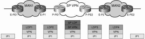 The VPN label remains untouched through the provider cloud as the provider switches traffic between its P-PEs based on the additional SP-LDP label, which achieves the desired tunneling of the extended LSP. Thus, the provider VPN label participates in the formation of the enterprise-extended LSP as it is "tunneled" through the provider network. The result is that it acts as a single hop in the extended enterprise LSP, as shown in Figure 7-11. Although technically optimal, this solution is rare to find because few providers offer CsC as a service to enterprises. The reasons are many, most of them business related. Only time will tell how these business models evolve and whether CsC will become a standard part of the service provider VPN offering. One thing is certain, the pressure from enterprises to obtain such services is constantly growing as more enterprises deploy MPLS and seek to extend VNs over the WAN. Using CsC for Segmented Branch AggregationYou can also use CsC to extend the segmentation between a campus network and the enterprise's branches. The branches are aggregated over an IP VPN; therefore, they enjoy any-to-any connectivity. By using CsC to support the branch segmentation, you preserve the any-to-any connectivity. In this scenario, the branch access router acts as a PE. This is just a degenerate case of the CsC scenario discussed in the previous section. The sole difference between the scenarios is that in the previous case, the exchange of IPv4 routes and labels was performed by an E-P router. In this scenario, the E-PE at the branch is directly connected to the backbone carrier and must now exchange IPv4 routes and labels with the P-PE. Benefits and DrawbacksCsC is a clean, technical alternative to extending MPLS VPNs across an MPLS-based provider network. Some of the benefits and drawbacks of using a CsC service are listed here. The benefits include the following:
The main drawbacks include the following:
Currently CsC services are rarely offered to enterprises. Nevertheless, CsC has some desirable technical characteristics and in some cases it might be possible for the enterprise to procure these services from the provider. |
EAN: 2147483647
Pages: 128